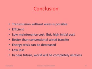
12/29/2015 1R.V.S.C.E.T. EEE DEPARTMENT
PRESENTED BY:-
M.SAI TEJA (14161-EE-042)
E.KUMAR (14161-EE-015)
S.SAI KIRAN(14161-EE-039)
SUBMITTED TO:-
SINGARENI COLLIRIES POLYTECHNIC
12/29/2015R.V.S.C.E.T. EEE DEPARTMENT 2
12/29/2015R.V.S.C.E.T. EEE DEPARTMENT
3
CONTENTS :-
1. INTRODUCTION & HISTORY
2. INDUCTIVE RESONANCE COUPLING
3. CONSTRUCTION &OPERATION
4. APPLICATION & FUTURE
What is WitriCity?
12/29/2015mosam EEE DEPARTMENT4
Witricity is nothing but wireless electricity.
Transmission of electrical energy from one
object to another without the use of wires is
called Witricity.
Because of Witricity some of the devices
won’t require batteries to operate .
Why we need Witricity?.
WE USE WIRES…
12/29/2015 5R.V.S.C.E.T. EEE DEPARTMENT
History of Wireless Power:
 In 1899, Sir NikolaTesla Proposed a method
ofWireless Power Transmission.
 As it is in Radiative mode, most of the Power
was wasted and has less efficiency.
 Able to light lamps over 25 miles away
without using wires
The team from Massachusetts
Institute of Technology, who call
their invention ‘WiTricity‘.
In the first successful trial of its
kind, the team was able to
illuminate a 60-watt light bulb 7ft
away.
12/29/2015 6R.V.S.C.E.T. EEE DEPARTMENT
TYPES OF WITRICITY
Inductive Coupling
Resonant Inductive Coupling
12/29/2015R.V.S.C.E.T. EEE DEPARTMENT
7
Inductive coupling
• Primary and secondary coils- not connected
with wires.
• Energy transfer - due to Mutual Induction.
12/29/2015 R.V.S.C.E.T. EEE DEPARTMENT 8
Inductive coupling (contd…)
• Transformer is also an example
• Energy transfer devices are usually air-cored
• Wireless Charging Pad(WCP),electric brushes
are some examples
• On a WCP, the devices are to be kept, battery
will be automatically charged.
12/29/2015 R.V.S.C.E.T. EEE DEPARTMENT 9
Resonance Inductive
Coupling(RIC)
12/29/2015R.V.S.C.E.T. EEE DEPARTMENT10
 Combination of inductive coupling and
resonance
 Resonance makes two objects interact very
strongly
How resonance in RIC?
 Coil provides the inductance
 Capacitor is connected parallel to the
coil
 Energy will be shifting back and forth
between magnetic field surrounding
the coil and electric field around the
capacitor
 High resonant frequency
12/29/2015 R.V.S.C.E.T. EEE DEPARTMENT 11
 RIC is highly efficient
 RIC has much greater range than inductive
coupling
 RIC is directional when compared to
inductive coupling
 RIC can be one-to-many. But usually
inductive coupling is one-to-one
 Devices using RIC technique are highly
portable
12/29/2015R.V.S.C.E.T. EEE DEPARTMENT 12
BASIC TECHNOLOGY :-
WORKING CYCLE
12/29/2015 R.V.S.C.E.T. EEE DEPARTMENT
Electricity
Magnetism
Electromagn
etism
Magnetic
Induction
Energy/Pow
er Coupling
Resonance
Resonant
Magnetic
Coupling
AIM OF THE CIRCUITS :-
12/29/2015 R.V.S.C.E.T. EEE DEPARTMENT
1.
• CONVERTION OF NORMAL
FREQUENCY TO HIGH
FREQUENCY
2.
• CONVERTION OF INDUSED
HIGH FREQUENCY TO
NORMAL FREQUENCY
CONVERTION OF LOW FREQUENCY
INTO HIGH FREQUENCY :-
12/29/2015 R.V.S.C.E.T. EEE DEPARTMENT
1. OSCILATOR
2. INVERTOR
3. INDUCTION COILS
FIRST METHOD :-
12/29/2015 R.V.S.C.E.T. EEE DEPARTMENT
USE OF OSCILATOR TO GENERATE A FIXED HIGH
FREQUENCY
SECOND METHOD :-
12/29/2015 R.V.S.C.E.T. EEE DEPARTMENT
USE OF INVERTOR TO GENERATE REGULATED HIGH
FREQUENCY
THIRD METHOD :-
12/29/2015R.V.S.C.E.T. EEE DEPARTMENT
USE OF INDUCTION COIL WITH
PROPER TUNING
TRANSMITER CIRCUIT :- BY MULTISIM
12/29/2015 R.V.S.C.E.T. EEE DEPARTMENT
RECIVER CIRCUIT:- BY MULTISIM
12/29/2015 R.V.S.C.E.T. EEE DEPARTMENT
COMPLETE BLOCK DYGRAM:-
12/29/2015 R.V.S.C.E.T. EEE DEPARTMENT
No wires
Need for battery is eliminated
 No e-waste
Efficient energy transfer
Harmless, if field strengths under safety
levels
Maintenance cost is less
12/29/2015R.V.S.C.E.T. EEE DEPARTMENT
22
Distance constraint
Field strengths have to be under safety
levels
Initial cost is high
In RIC, tuning is difficult
High frequency signals must be the supply
12/29/2015R.V.S.C.E.T. EEE DEPARTMENT
23
 Electric automobile charging
 Static and moving
 Consumer electronics
 Industrial purposes
12/29/2015 R.V.S.C.E.T. EEE DEPARTMENT 24
IN MEDICAL
12/29/2015 R.V.S.C.E.T. EEE DEPARTMENT 25
12/29/2015 R.V.S.C.E.T. EEE DEPARTMENT 26
eliminating the need for disposable batteries or
a power cord connecting the helmet
12/29/2015 R.V.S.C.E.T. EEE DEPARTMENT 27
IN CONSUMER ELECTRONICS
12/29/2015R.V.S.C.E.T. EEE DEPARTMENT28
Conclusion
• Transmission without wires is possible
• Efficient
• Low maintenance cost. But, high initial cost
• Better than conventional wired transfer
• Energy crisis can be decreased
• Low loss
• In near future, world will be completely wireless
12/29/2015 R.V.S.C.E.T. EEE DEPARTMENT 29
12/29/2015 R.V.S.C.E.T. EEE DEPARTMENT 30

wire less power transfer system

  • 1.
  • 2.
    PRESENTED BY:- M.SAI TEJA(14161-EE-042) E.KUMAR (14161-EE-015) S.SAI KIRAN(14161-EE-039) SUBMITTED TO:- SINGARENI COLLIRIES POLYTECHNIC 12/29/2015R.V.S.C.E.T. EEE DEPARTMENT 2
  • 3.
    12/29/2015R.V.S.C.E.T. EEE DEPARTMENT 3 CONTENTS:- 1. INTRODUCTION & HISTORY 2. INDUCTIVE RESONANCE COUPLING 3. CONSTRUCTION &OPERATION 4. APPLICATION & FUTURE
  • 4.
    What is WitriCity? 12/29/2015mosamEEE DEPARTMENT4 Witricity is nothing but wireless electricity. Transmission of electrical energy from one object to another without the use of wires is called Witricity. Because of Witricity some of the devices won’t require batteries to operate .
  • 5.
    Why we needWitricity?. WE USE WIRES… 12/29/2015 5R.V.S.C.E.T. EEE DEPARTMENT
  • 6.
    History of WirelessPower:  In 1899, Sir NikolaTesla Proposed a method ofWireless Power Transmission.  As it is in Radiative mode, most of the Power was wasted and has less efficiency.  Able to light lamps over 25 miles away without using wires The team from Massachusetts Institute of Technology, who call their invention ‘WiTricity‘. In the first successful trial of its kind, the team was able to illuminate a 60-watt light bulb 7ft away. 12/29/2015 6R.V.S.C.E.T. EEE DEPARTMENT
  • 7.
    TYPES OF WITRICITY InductiveCoupling Resonant Inductive Coupling 12/29/2015R.V.S.C.E.T. EEE DEPARTMENT 7
  • 8.
    Inductive coupling • Primaryand secondary coils- not connected with wires. • Energy transfer - due to Mutual Induction. 12/29/2015 R.V.S.C.E.T. EEE DEPARTMENT 8
  • 9.
    Inductive coupling (contd…) •Transformer is also an example • Energy transfer devices are usually air-cored • Wireless Charging Pad(WCP),electric brushes are some examples • On a WCP, the devices are to be kept, battery will be automatically charged. 12/29/2015 R.V.S.C.E.T. EEE DEPARTMENT 9
  • 10.
    Resonance Inductive Coupling(RIC) 12/29/2015R.V.S.C.E.T. EEEDEPARTMENT10  Combination of inductive coupling and resonance  Resonance makes two objects interact very strongly
  • 11.
    How resonance inRIC?  Coil provides the inductance  Capacitor is connected parallel to the coil  Energy will be shifting back and forth between magnetic field surrounding the coil and electric field around the capacitor  High resonant frequency 12/29/2015 R.V.S.C.E.T. EEE DEPARTMENT 11
  • 12.
     RIC ishighly efficient  RIC has much greater range than inductive coupling  RIC is directional when compared to inductive coupling  RIC can be one-to-many. But usually inductive coupling is one-to-one  Devices using RIC technique are highly portable 12/29/2015R.V.S.C.E.T. EEE DEPARTMENT 12
  • 13.
    BASIC TECHNOLOGY :- WORKINGCYCLE 12/29/2015 R.V.S.C.E.T. EEE DEPARTMENT Electricity Magnetism Electromagn etism Magnetic Induction Energy/Pow er Coupling Resonance Resonant Magnetic Coupling
  • 14.
    AIM OF THECIRCUITS :- 12/29/2015 R.V.S.C.E.T. EEE DEPARTMENT 1. • CONVERTION OF NORMAL FREQUENCY TO HIGH FREQUENCY 2. • CONVERTION OF INDUSED HIGH FREQUENCY TO NORMAL FREQUENCY
  • 15.
    CONVERTION OF LOWFREQUENCY INTO HIGH FREQUENCY :- 12/29/2015 R.V.S.C.E.T. EEE DEPARTMENT 1. OSCILATOR 2. INVERTOR 3. INDUCTION COILS
  • 16.
    FIRST METHOD :- 12/29/2015R.V.S.C.E.T. EEE DEPARTMENT USE OF OSCILATOR TO GENERATE A FIXED HIGH FREQUENCY
  • 17.
    SECOND METHOD :- 12/29/2015R.V.S.C.E.T. EEE DEPARTMENT USE OF INVERTOR TO GENERATE REGULATED HIGH FREQUENCY
  • 18.
    THIRD METHOD :- 12/29/2015R.V.S.C.E.T.EEE DEPARTMENT USE OF INDUCTION COIL WITH PROPER TUNING
  • 19.
    TRANSMITER CIRCUIT :-BY MULTISIM 12/29/2015 R.V.S.C.E.T. EEE DEPARTMENT
  • 20.
    RECIVER CIRCUIT:- BYMULTISIM 12/29/2015 R.V.S.C.E.T. EEE DEPARTMENT
  • 21.
    COMPLETE BLOCK DYGRAM:- 12/29/2015R.V.S.C.E.T. EEE DEPARTMENT
  • 22.
    No wires Need forbattery is eliminated  No e-waste Efficient energy transfer Harmless, if field strengths under safety levels Maintenance cost is less 12/29/2015R.V.S.C.E.T. EEE DEPARTMENT 22
  • 23.
    Distance constraint Field strengthshave to be under safety levels Initial cost is high In RIC, tuning is difficult High frequency signals must be the supply 12/29/2015R.V.S.C.E.T. EEE DEPARTMENT 23
  • 24.
     Electric automobilecharging  Static and moving  Consumer electronics  Industrial purposes 12/29/2015 R.V.S.C.E.T. EEE DEPARTMENT 24
  • 25.
  • 26.
    12/29/2015 R.V.S.C.E.T. EEEDEPARTMENT 26 eliminating the need for disposable batteries or a power cord connecting the helmet
  • 27.
  • 28.
  • 29.
    Conclusion • Transmission withoutwires is possible • Efficient • Low maintenance cost. But, high initial cost • Better than conventional wired transfer • Energy crisis can be decreased • Low loss • In near future, world will be completely wireless 12/29/2015 R.V.S.C.E.T. EEE DEPARTMENT 29
  • 30.