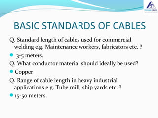
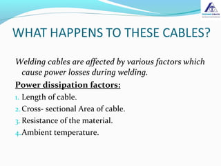
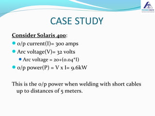
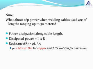
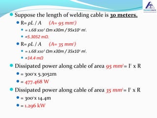
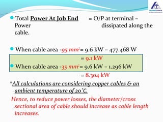
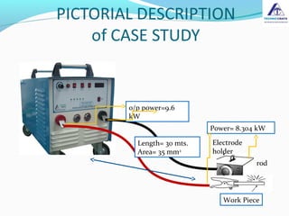
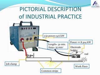
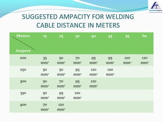
By :
Mahendra Bandal
Technocrats Plasma Systems Private Limited Mumbai
Welding cables- the current carrier between machine
and the job.
Welding cable size selection- an important but
commonly unknown knowledge; often ignored by
users as well as manufacturers.
Insufficient cable size- the cause of unsatisfactory
performance many a times which goes unnoticed;
ultimately service dept. and goodwill of the company
suffers.
Q. Standard length of cables used for commercial
welding e.g. Maintenance workers, fabricators etc. ?
 3-5 meters.
Q. What conductor material should ideally be used?
Copper
Q. Range of cable length in heavy industrial
applications e.g. Tube mill, ship yards etc. ?
15-50 meters.
Welding cables are affected by various factors which
cause power losses during welding.
Power dissipation factors:
1. Length of cable.
2.Cross- sectional Area of cable.
3. Resistance of the material.
4.Ambient temperature.
Consider Solaris 400:
o/p current(I)= 300 amps
Arc voltage(V)= 32 volts
Arc voltage = 20+(0.04*I)
o/p power(P) = V x I= 9.6kW
This is the o/p power when welding with short cables
up to distances of 5 meters.
Now,
What about o/p power when welding cables used are of
lengths ranging up to 50 meters?
Power dissipation along cable length.
Dissipated power = I2
x R
Resistance(R) = ρL / A
ρ= 1.68 x10⁻⁸
Ωm for copper and 2.65 x10⁻⁸
Ωm for aluminum.
Suppose the length of welding cable is 30 meters.
R= ρL / A (A= 95 mm2
)
 = 1.68 x10-8
Ωm x30m / 95x10-6
m2
.
 =5.3052 mΩ.
R= ρL / A (A= 35 mm2
)
 = 1.68 x10-8
Ωm x30m / 35x10-6
m2
.
 =14.4 mΩ
Dissipated power along cable of area 95 mm2
= I2
x R
= 3002
x 5.3052m
= 477.468 W
Dissipated power along cable of area 35 mm2
= I2
x R
= 3002
x 14.4m
= 1.296 kW
Total Power At Job End = O/P at terminal –
Power dissipated along the
cable.
When cable area -95 mm2
= 9.6 kW – 477.468 W
= 9.1 kW
When cable area -35 mm2
= 9.6 kW – 1.296 kW
= 8.304 kW
*All calculations are considering copper cables & an
ambient temperature of 20˚C.
Hence, to reduce power losses, the diameter/cross
sectional area of cable should increase as cable length
increases.
o/p power=9.6
kW
Length= 30 mts.
Area= 35 mm2
Work Piece
Electrode
holder
rod
Power= 8.304 kW
COMMON INDUSTRIAL PRACTICE
The case study was considering both +ve & -ve cables
to be of 30 mtr. Length.
Now, as per common industrial practice, the job cable
is replaced by common strips, kept one on top of the
other.
This leads to a huge voltage drop at the contact point
as the contact area is very small, leading to sparks
during welding.
This drop causes further power losses.
o/p power=9.6 kW
Length= 30 mts.
Area= 35 mm2
Work Piece
Electrode
holder
rod
Power << 8.304 kW
Job clamp
Common strips
Meters
Ampere
15 25 30 40 45 55 60
200 35
mm2
50
mm2
70
mm2
95
mm2
95
mm2
120
mm2
120
mm2
250 50
mm2
50
mm2
95
mm2
120
mm2
120
mm2
300 50
mm2
70
mm2
95
mm2
120
mm2
350 50
mm2
95
mm2
120
mm2
400 70
mm2
120
mm2
SUGGESTED AMPACITY FOR WELDING
CABLE DISTANCE IN METERS
The first preference of any user when purchasing an
inverter machine is the low power consumption of
this technology.
The excess power losses in the cables(around 1 kW)
increase the machine’s power losses, making the low
power consumption plus point ineffective.
Advice our valued customers to save power by
making the right choice.
Welding Cable Selection Guide

Welding Cable Selection Guide

  • 1.
    By : Mahendra Bandal TechnocratsPlasma Systems Private Limited Mumbai
  • 2.
    Welding cables- thecurrent carrier between machine and the job. Welding cable size selection- an important but commonly unknown knowledge; often ignored by users as well as manufacturers. Insufficient cable size- the cause of unsatisfactory performance many a times which goes unnoticed; ultimately service dept. and goodwill of the company suffers.
  • 3.
    Q. Standard lengthof cables used for commercial welding e.g. Maintenance workers, fabricators etc. ?  3-5 meters. Q. What conductor material should ideally be used? Copper Q. Range of cable length in heavy industrial applications e.g. Tube mill, ship yards etc. ? 15-50 meters.
  • 4.
    Welding cables areaffected by various factors which cause power losses during welding. Power dissipation factors: 1. Length of cable. 2.Cross- sectional Area of cable. 3. Resistance of the material. 4.Ambient temperature.
  • 5.
    Consider Solaris 400: o/pcurrent(I)= 300 amps Arc voltage(V)= 32 volts Arc voltage = 20+(0.04*I) o/p power(P) = V x I= 9.6kW This is the o/p power when welding with short cables up to distances of 5 meters.
  • 6.
    Now, What about o/ppower when welding cables used are of lengths ranging up to 50 meters? Power dissipation along cable length. Dissipated power = I2 x R Resistance(R) = ρL / A ρ= 1.68 x10⁻⁸ Ωm for copper and 2.65 x10⁻⁸ Ωm for aluminum.
  • 7.
    Suppose the lengthof welding cable is 30 meters. R= ρL / A (A= 95 mm2 )  = 1.68 x10-8 Ωm x30m / 95x10-6 m2 .  =5.3052 mΩ. R= ρL / A (A= 35 mm2 )  = 1.68 x10-8 Ωm x30m / 35x10-6 m2 .  =14.4 mΩ Dissipated power along cable of area 95 mm2 = I2 x R = 3002 x 5.3052m = 477.468 W Dissipated power along cable of area 35 mm2 = I2 x R = 3002 x 14.4m = 1.296 kW
  • 8.
    Total Power AtJob End = O/P at terminal – Power dissipated along the cable. When cable area -95 mm2 = 9.6 kW – 477.468 W = 9.1 kW When cable area -35 mm2 = 9.6 kW – 1.296 kW = 8.304 kW *All calculations are considering copper cables & an ambient temperature of 20˚C. Hence, to reduce power losses, the diameter/cross sectional area of cable should increase as cable length increases.
  • 9.
    o/p power=9.6 kW Length= 30mts. Area= 35 mm2 Work Piece Electrode holder rod Power= 8.304 kW
  • 10.
    COMMON INDUSTRIAL PRACTICE Thecase study was considering both +ve & -ve cables to be of 30 mtr. Length. Now, as per common industrial practice, the job cable is replaced by common strips, kept one on top of the other. This leads to a huge voltage drop at the contact point as the contact area is very small, leading to sparks during welding. This drop causes further power losses.
  • 11.
    o/p power=9.6 kW Length=30 mts. Area= 35 mm2 Work Piece Electrode holder rod Power << 8.304 kW Job clamp Common strips
  • 12.
    Meters Ampere 15 25 3040 45 55 60 200 35 mm2 50 mm2 70 mm2 95 mm2 95 mm2 120 mm2 120 mm2 250 50 mm2 50 mm2 95 mm2 120 mm2 120 mm2 300 50 mm2 70 mm2 95 mm2 120 mm2 350 50 mm2 95 mm2 120 mm2 400 70 mm2 120 mm2 SUGGESTED AMPACITY FOR WELDING CABLE DISTANCE IN METERS
  • 13.
    The first preferenceof any user when purchasing an inverter machine is the low power consumption of this technology. The excess power losses in the cables(around 1 kW) increase the machine’s power losses, making the low power consumption plus point ineffective. Advice our valued customers to save power by making the right choice.