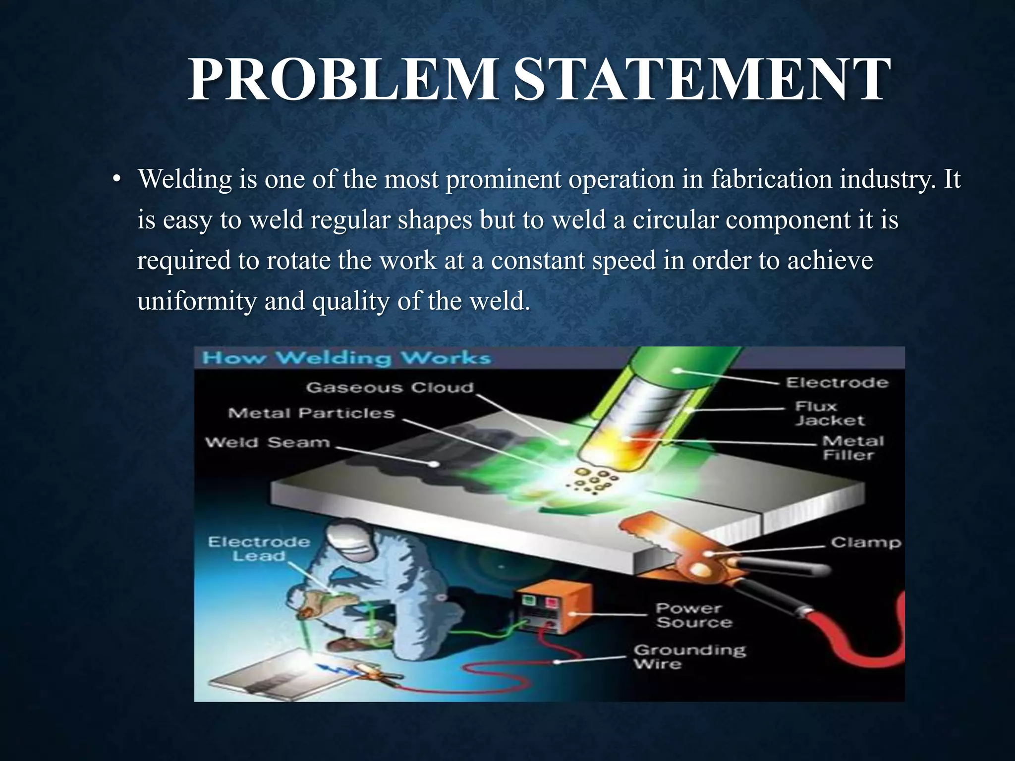
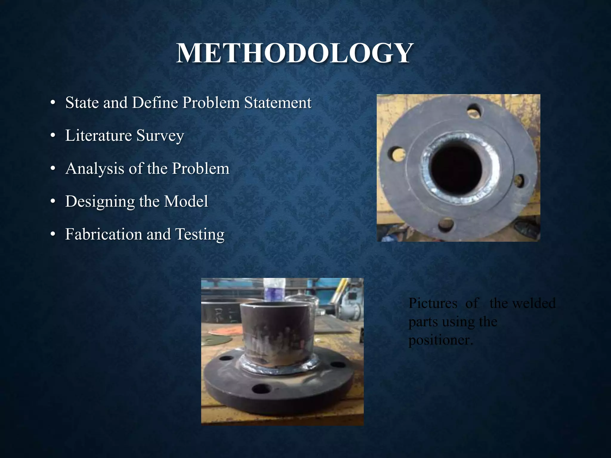
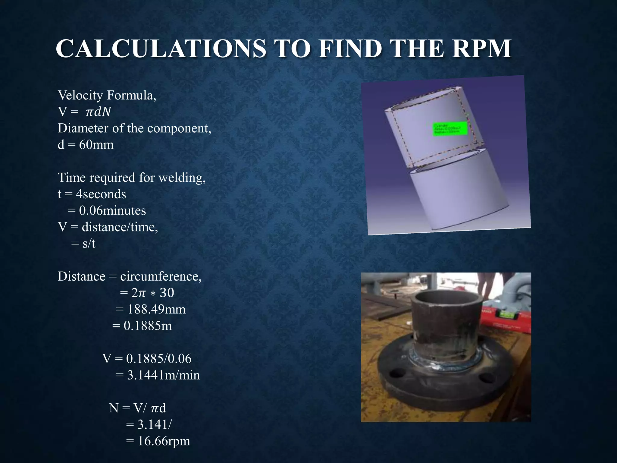
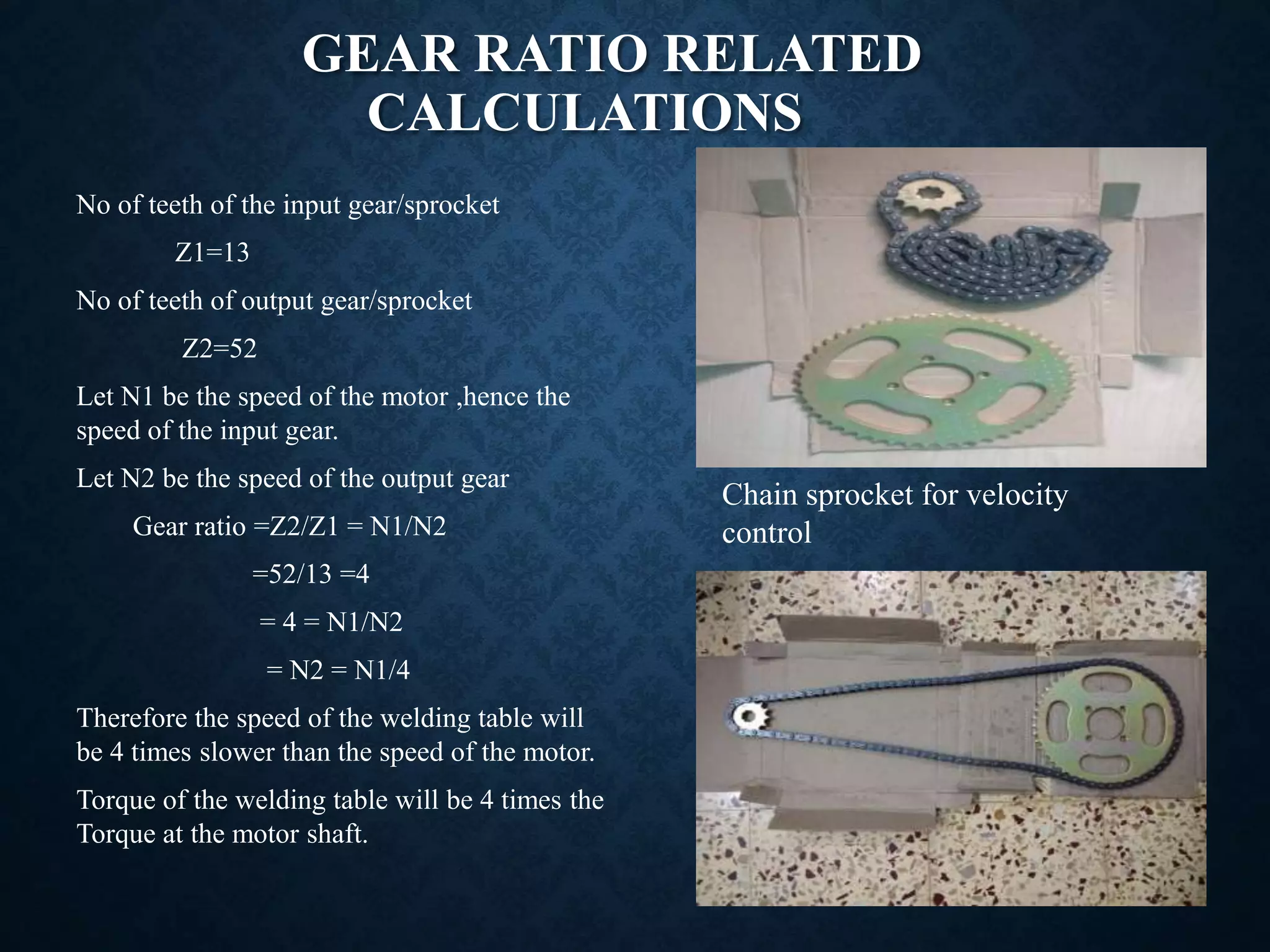
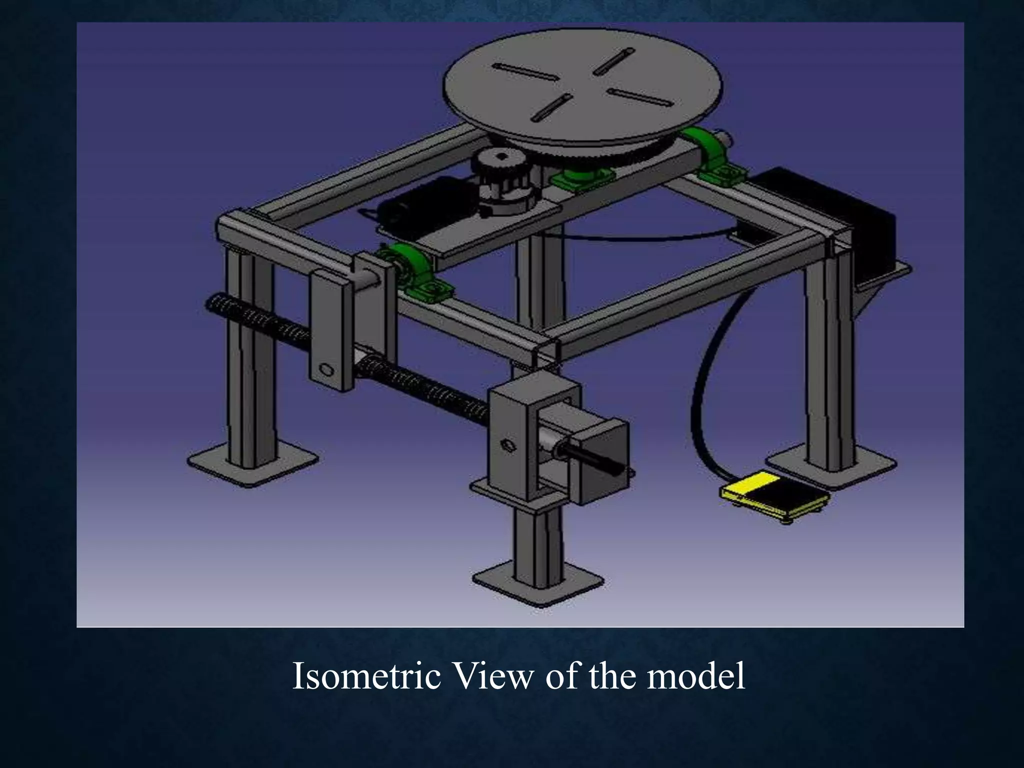
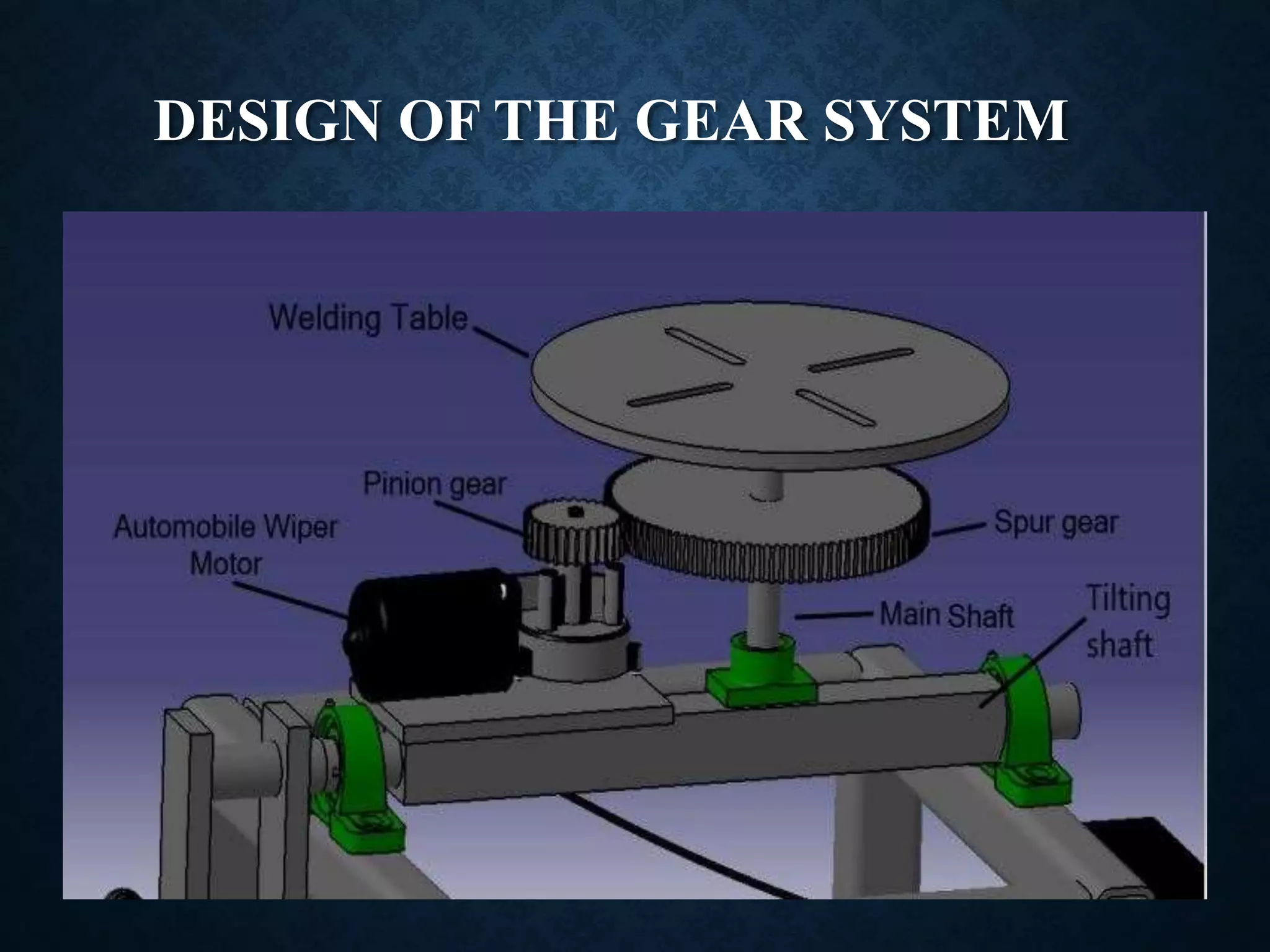
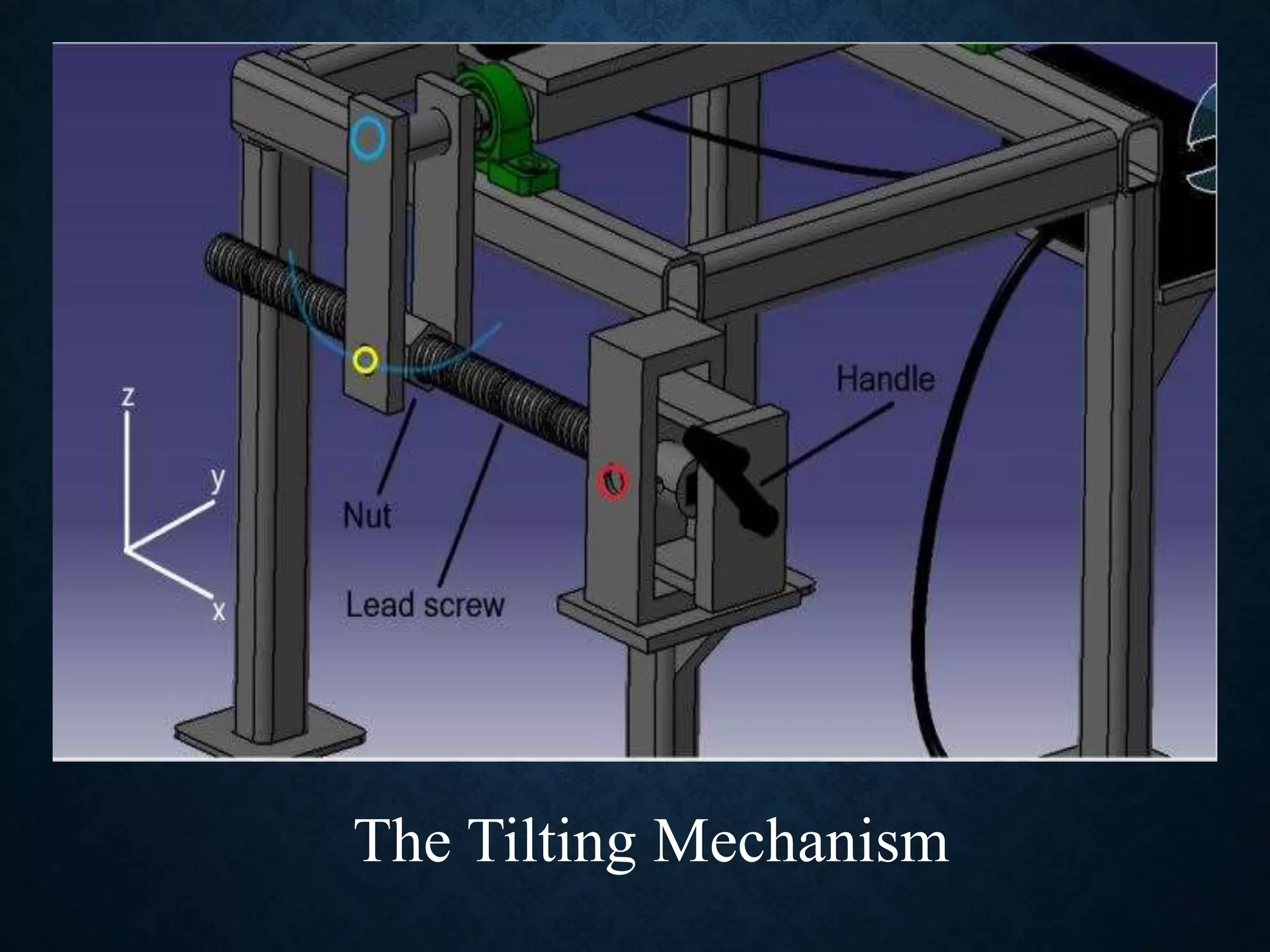
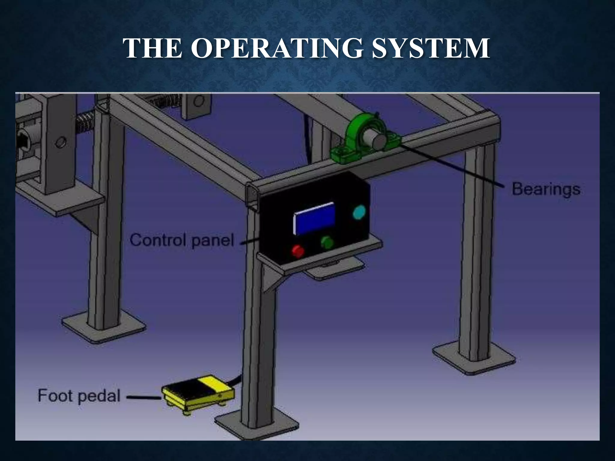
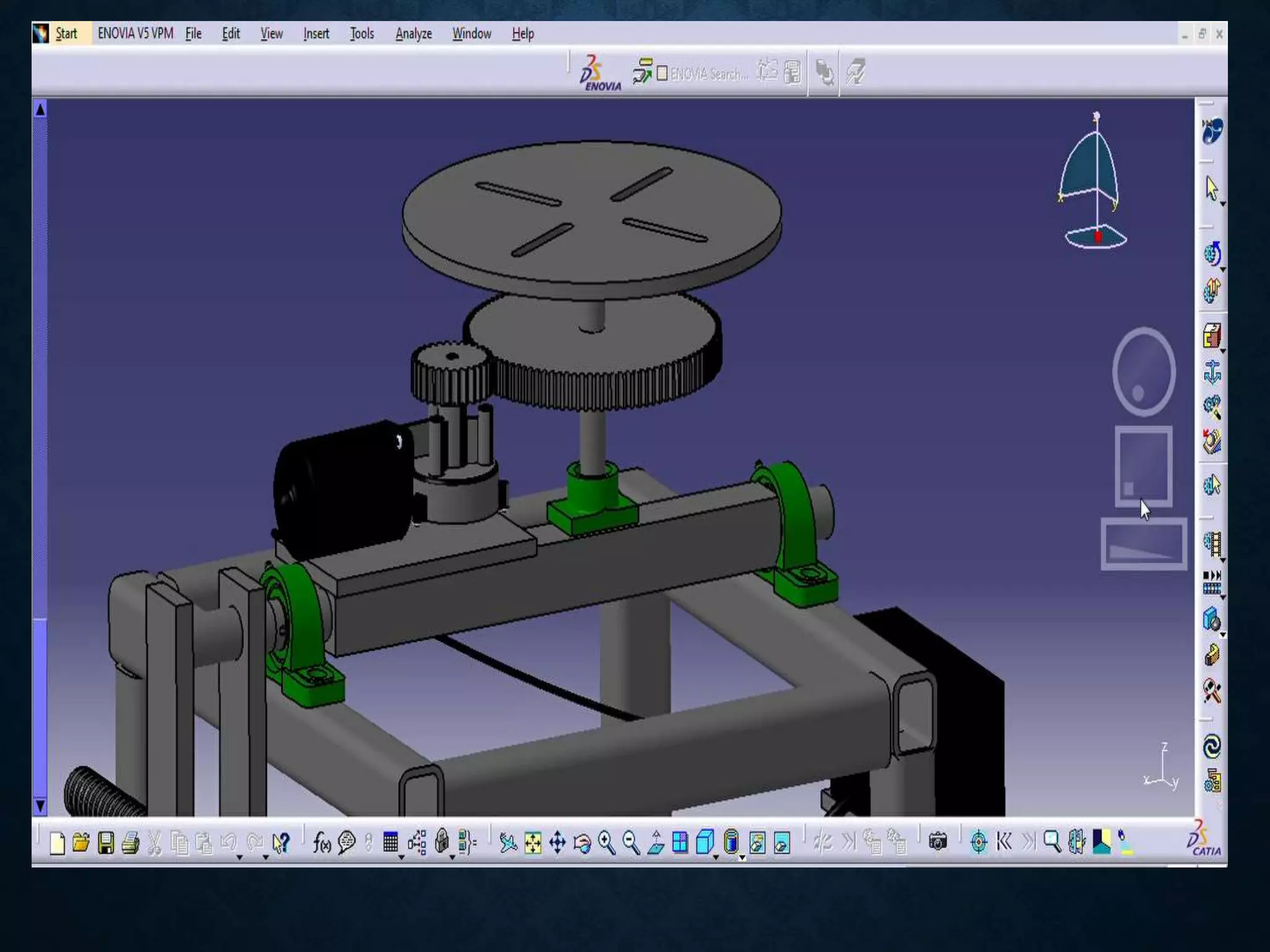
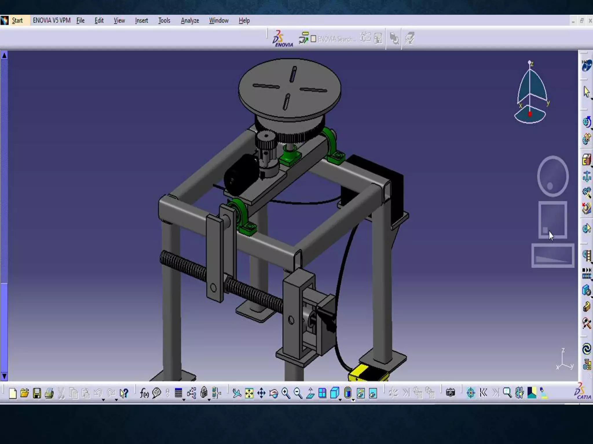
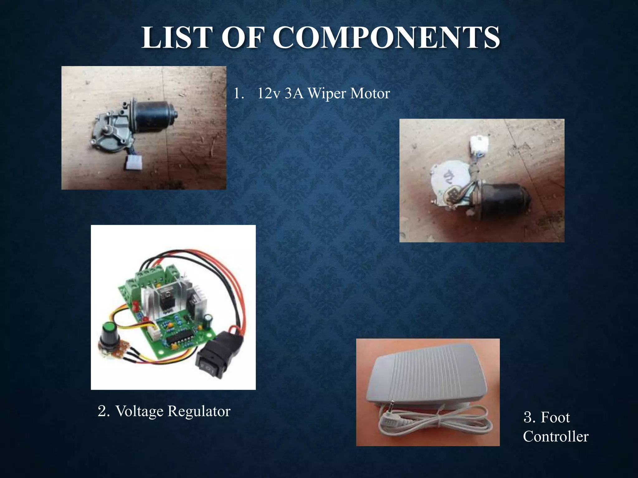
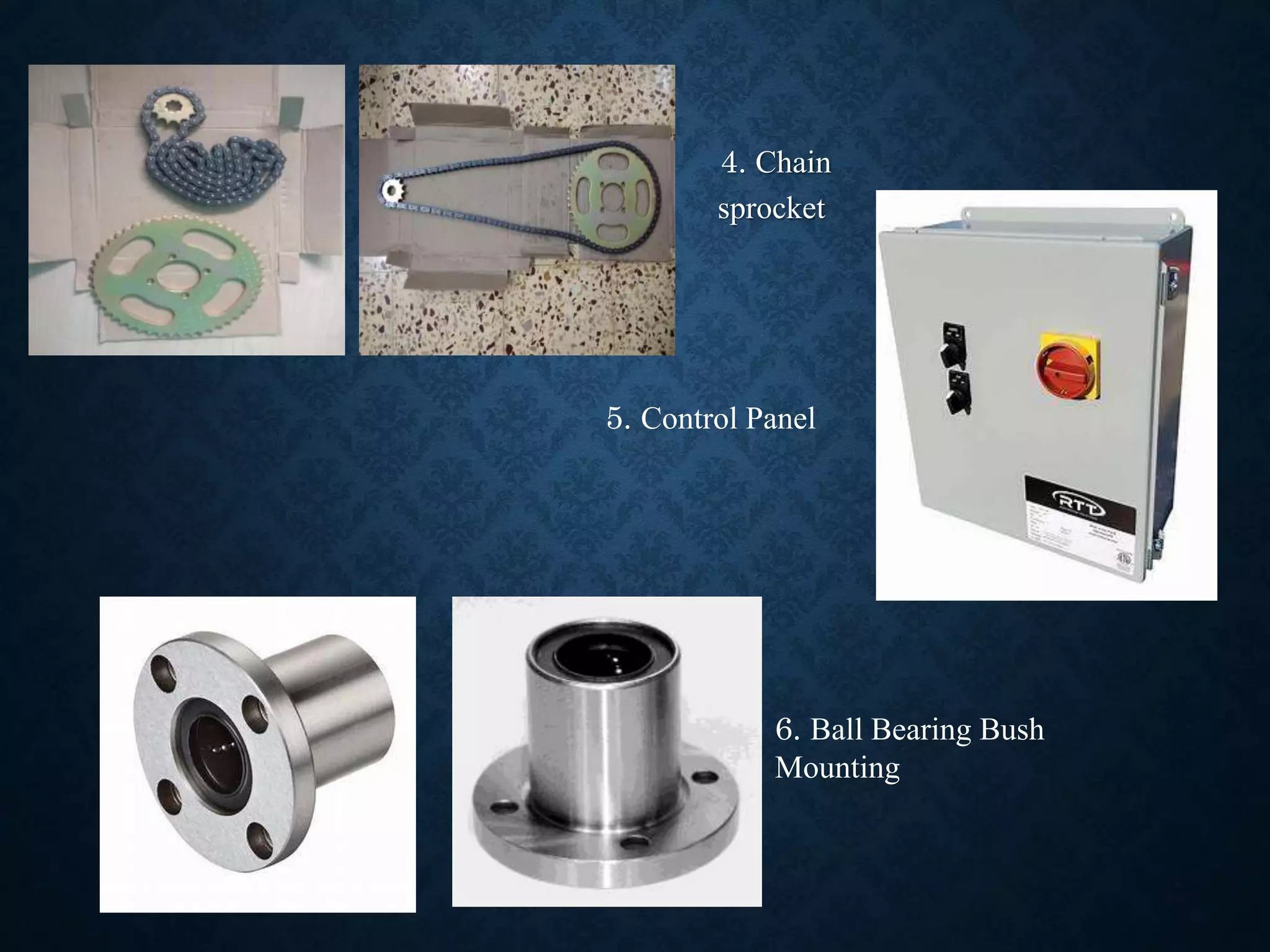
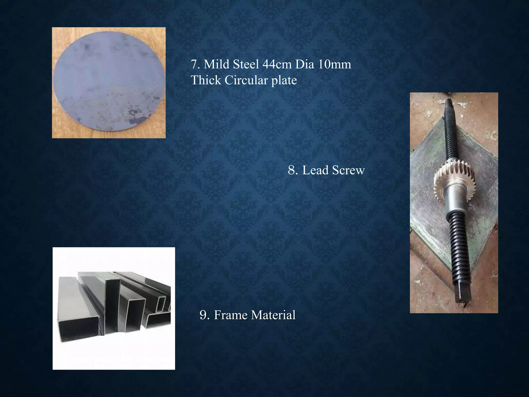
FINAL YEAR PROJECT
(FINAL PHASE)
Name USN
Aditya Gurav 2GI17ME010
Neha Kadam 2GI17ME077
Ayaan Munshi 2GI17ME001
Amareshwar Khot 2GI17ME019
B-37 Guide: Prof. V.V. Deshpande
CONTENTS
• Problem Statement
• Title
• Methodology
• Design
• Calculations
• Components used
• Conclusion
• Scope for future work
• References
PROBLEM STATEMENT
• Welding is one of the most prominent operation in fabrication industry. It
is easy to weld regular shapes but to weld a circular component it is
required to rotate the work at a constant speed in order to achieve
uniformity and quality of the weld.
DESIGN
AND
FABRICATION
OF ELECTRONIC
WELDING
POSITIONER
METHODOLOGY
• State and Define Problem Statement
• Literature Survey
• Analysis of the Problem
• Designing the Model
• Fabrication and Testing
Pictures of the welded
parts using the
positioner.
CALCULATIONS TO FIND THE RPM
Velocity Formula,
V = 𝜋𝑑𝑁
Diameter of the component,
d = 60mm
Time required for welding,
t = 4seconds
= 0.06minutes
V = distance/time,
= s/t
Distance = circumference,
= 2𝜋 ∗ 30
= 188.49mm
= 0.1885m
V = 0.1885/0.06
= 3.1441m/min
N = V/ 𝜋d
= 3.141/
= 16.66rpm
GEAR RATIO RELATED
CALCULATIONS
Chain sprocket for velocity
control
No of teeth of the input gear/sprocket
Z1=13
No of teeth of output gear/sprocket
Z2=52
Let N1 be the speed of the motor ,hence the
speed of the input gear.
Let N2 be the speed of the output gear
Gear ratio =Z2/Z1 = N1/N2
=52/13 =4
= 4 = N1/N2
= N2 = N1/4
Therefore the speed of the welding table will
be 4 times slower than the speed of the motor.
Torque of the welding table will be 4 times the
Torque at the motor shaft.
Isometric View of the model
DESIGN OF THE GEAR SYSTEM
The Tilting Mechanism
THE OPERATING SYSTEM
LIST OF COMPONENTS
1. 12v 3A Wiper Motor
2. Voltage Regulator 3. Foot
Controller
4. Chain
sprocket
6. Ball Bearing Bush
Mounting
5. Control Panel
9. Frame Material
7. Mild Steel 44cm Dia 10mm
Thick Circular plate
8. Lead Screw
CONCLUSION
1. By cylindrical welding positioner we can weld cylindrical work piece
and valve flanges easily, which makes productivity higher and also
reduces the work of labor.
2. Welding positioner totally satisfies the requirements of the job.
3. It considerably reduces the operators fatigue and time required for the
process.
4. This positioner requires less amount of power so it helps to achieve
minimum power consumption.
5. Precise and the noiseless operation is generated, it handles the bulky
assembly efficiently. Less skilled worker is required.
SCOPE OF FUTURE WORK
1. In this welding positioner, welding gun is held in hand which can be
automated.
2. In case of gas welding, the whole machine can be automated by
manufacturing a stand for holding the gun.
3. A larger chuck can be used for larger diameter work pieces.
4. Entire positioner can be controlled using a microprocessor to increase
automation.
5. Currently the welding positioner is used with welding gun which is fed
manually and has a spring return mechanism which can be replaced and
automated with pneumatic cylinders.
6. The entire positioner can be controlled using Microprocessors to increase
automation
REFERENCES
• Optimizing and analysis of parameter for pipe welding by Bhargav
C. Patel, Jaivesh Gandhi(2013).
• A Review on Design of Fixtures by Shailesh S. Pachbhai, Laukik P.
Raut(2014).
• Safety considerations in a welding process a review by Kapil Singh,
Ankush Anand(2013).
• Optimization of special purpose rotational MIG welding By
Experimental and Taguchi Technique by Mohan B. Raut, S.N.
Shelke(2014)
Project ppt.pptx

Project ppt.pptx

  • 1.
    FINAL YEAR PROJECT (FINALPHASE) Name USN Aditya Gurav 2GI17ME010 Neha Kadam 2GI17ME077 Ayaan Munshi 2GI17ME001 Amareshwar Khot 2GI17ME019 B-37 Guide: Prof. V.V. Deshpande
  • 2.
    CONTENTS • Problem Statement •Title • Methodology • Design • Calculations • Components used • Conclusion • Scope for future work • References
  • 3.
    PROBLEM STATEMENT • Weldingis one of the most prominent operation in fabrication industry. It is easy to weld regular shapes but to weld a circular component it is required to rotate the work at a constant speed in order to achieve uniformity and quality of the weld.
  • 4.
  • 5.
    METHODOLOGY • State andDefine Problem Statement • Literature Survey • Analysis of the Problem • Designing the Model • Fabrication and Testing Pictures of the welded parts using the positioner.
  • 6.
    CALCULATIONS TO FINDTHE RPM Velocity Formula, V = 𝜋𝑑𝑁 Diameter of the component, d = 60mm Time required for welding, t = 4seconds = 0.06minutes V = distance/time, = s/t Distance = circumference, = 2𝜋 ∗ 30 = 188.49mm = 0.1885m V = 0.1885/0.06 = 3.1441m/min N = V/ 𝜋d = 3.141/ = 16.66rpm
  • 7.
    GEAR RATIO RELATED CALCULATIONS Chainsprocket for velocity control No of teeth of the input gear/sprocket Z1=13 No of teeth of output gear/sprocket Z2=52 Let N1 be the speed of the motor ,hence the speed of the input gear. Let N2 be the speed of the output gear Gear ratio =Z2/Z1 = N1/N2 =52/13 =4 = 4 = N1/N2 = N2 = N1/4 Therefore the speed of the welding table will be 4 times slower than the speed of the motor. Torque of the welding table will be 4 times the Torque at the motor shaft.
  • 8.
  • 9.
    DESIGN OF THEGEAR SYSTEM
  • 10.
  • 11.
  • 14.
    LIST OF COMPONENTS 1.12v 3A Wiper Motor 2. Voltage Regulator 3. Foot Controller
  • 15.
    4. Chain sprocket 6. BallBearing Bush Mounting 5. Control Panel
  • 16.
    9. Frame Material 7.Mild Steel 44cm Dia 10mm Thick Circular plate 8. Lead Screw
  • 17.
    CONCLUSION 1. By cylindricalwelding positioner we can weld cylindrical work piece and valve flanges easily, which makes productivity higher and also reduces the work of labor. 2. Welding positioner totally satisfies the requirements of the job. 3. It considerably reduces the operators fatigue and time required for the process. 4. This positioner requires less amount of power so it helps to achieve minimum power consumption. 5. Precise and the noiseless operation is generated, it handles the bulky assembly efficiently. Less skilled worker is required.
  • 18.
    SCOPE OF FUTUREWORK 1. In this welding positioner, welding gun is held in hand which can be automated. 2. In case of gas welding, the whole machine can be automated by manufacturing a stand for holding the gun. 3. A larger chuck can be used for larger diameter work pieces. 4. Entire positioner can be controlled using a microprocessor to increase automation. 5. Currently the welding positioner is used with welding gun which is fed manually and has a spring return mechanism which can be replaced and automated with pneumatic cylinders. 6. The entire positioner can be controlled using Microprocessors to increase automation
  • 19.
    REFERENCES • Optimizing andanalysis of parameter for pipe welding by Bhargav C. Patel, Jaivesh Gandhi(2013). • A Review on Design of Fixtures by Shailesh S. Pachbhai, Laukik P. Raut(2014). • Safety considerations in a welding process a review by Kapil Singh, Ankush Anand(2013). • Optimization of special purpose rotational MIG welding By Experimental and Taguchi Technique by Mohan B. Raut, S.N. Shelke(2014)