Download to read offline

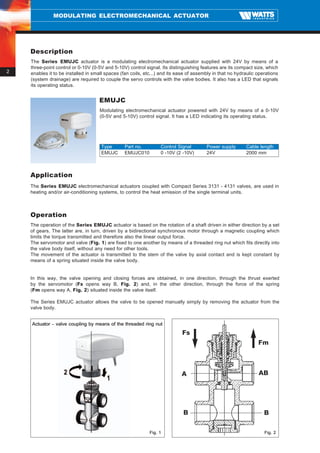
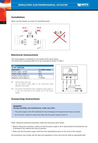
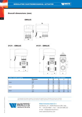

The document summarizes a modulating electromechanical actuator powered by 24V AC that controls the opening and closing of valves using a 0-10V control signal. It has a LED that indicates its operating status and uses a threaded ring nut to directly couple to Compact Series 3131-4131 valves. The actuator modulates the valve position proportionally based on the input control signal voltage between 0-10V.


