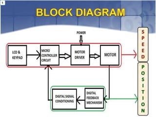
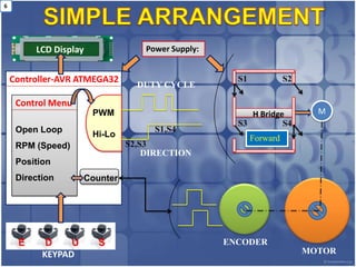
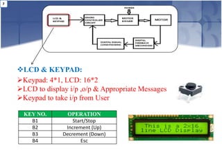
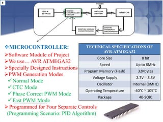
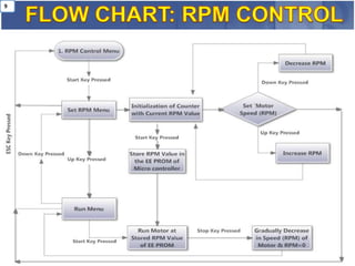
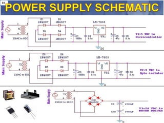
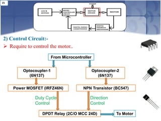
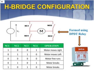
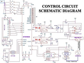
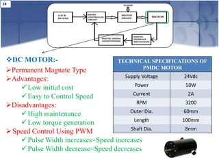
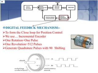
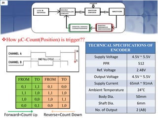
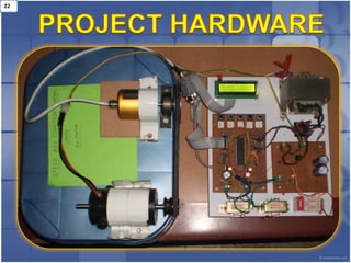
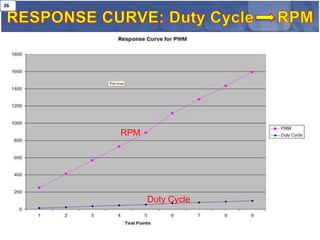
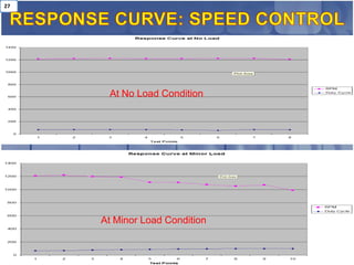
The AZBE6A8 is a PWM servo drive designed to drive brushless and brushed DC motors. It can provide up to 6A of peak current and 3A of continuous current from a 20-80VDC power supply. The drive includes protections against overvoltage, overcurrent, overheating and short circuits. It interfaces with digital controllers using a ±10V analog command input and supports feedback from encoders and Hall sensors.
The AZBE10A20 is an analog servo drive designed to drive brushless and brushed DC motors. It can provide up to 10A of continuous current and operates on an input voltage range of 40-175VDC. The drive has features such as four quadrant regenerative operation, direct board integration, encoder and tachometer feedback support, and hardware protections against overvoltage, overcurrent, and more.
The AZBE40A8 is a PWM servo drive designed to drive brushless and brushed DC motors. It can provide a peak current of 40A and continuous current of 20A, with a supply voltage range of 10-80VDC. The drive is fully protected against over-voltage, under-voltage, over-current and other faults. It supports various feedback and operation modes including encoder velocity control.
The AZBH6A8 is a PWM servo drive designed to drive brushless and brushed DC motors. It can provide up to 6A of peak current and 3A of continuous current. It interfaces with digital controllers using a ±10V analog command input and includes protections against overvoltage, overcurrent, and other faults. The drive requires only a single unregulated DC power supply between 20-80V.
The document describes an analog servo drive called the AZBE60A8. It is designed to drive brushless and brushed DC motors at high switching frequencies. Key specifications include a peak current of 60A, continuous current of 30A, and operating voltage range of 10-80VDC. It has protection against overvoltage, undervoltage, overcurrent and more. It can utilize encoder, hall sensor, or tachometer feedback and supports various motor and operation modes.
The document provides specifications for the AZBE25A20 analog servo drive. The drive is designed to drive brushless and brushed DC motors at high switching frequencies up to 25A continuous current. It has features like four quadrant regenerative operation, direct board integration, encoder and tachometer feedback support, and hardware protections. The drive requires only a single DC power supply and complies with safety and emissions standards.
The document provides specifications for the AZBE20A8 analog servo drive. Some key details:
- It is designed to drive brushless and brushed DC motors at high switching frequency and can integrate directly into a PCB.
- It provides overcurrent, overvoltage, and other hardware protections. Feedback can be provided by encoders, hall sensors, or tachometers.
- It has a peak current of 20A, continuous current of 12A, and operates from a 10-80VDC power supply. Modes include current control, duty cycle, and velocity control.
The AZBDC25A20 is a PWM servo drive designed to drive brushless and brushed DC motors. It has a peak current of 25A, continuous current of 12.5A, and operates on a supply voltage of 40-175VDC. The drive provides motor control and protection from over/under voltage, overcurrent, and overheating. It interfaces with digital controllers using PWM and direction inputs.
The document provides specifications for the AZBH25A20 analog servo drive. The drive is designed to drive brushless and brushed DC motors at high switching frequencies. It has a peak current of 25A, continuous current of 12.5A, and operates on a DC supply voltage of 40-175VDC. The drive provides various protection features and supports different feedback and operation modes.
The AZBH60A8 analog servo drive is designed to drive brushless and brushed DC motors at high switching frequencies. It can provide up to 60A of peak current and 30A of continuous current from a 10-80VDC power supply. The drive has protections against overvoltage, undervoltage, overcurrent, overheating and other faults. It interfaces with digital controllers using analog +/-10V commands and supports Hall sensor or tachometer feedback.
The AZ40A8DDC is a PWM servo drive designed to drive DC motors at high switching frequencies. It can provide up to 40A of peak current and 20A of continuous current from a 10-80VDC power supply. The drive is compact and lightweight for direct integration into PCBs. It has full protection against over-voltage, under-voltage, over-current and other faults.
The document describes the Analog Servo Drive AZBH40A8. It is designed to drive brushless and brushed DC motors at high switching frequencies. It can provide a peak current of 40A and continuous current of 20A, with a supply voltage range of 10-80VDC. The drive supports various feedback and operation modes, and includes protections for overvoltage, overcurrent, overheating and more.
The AZ60A8DDC is a PWM servo drive designed to drive brush-type DC motors at high switching frequencies. It has a peak current of 60A, continuous current of 30A, and operates from 10-80VDC. The drive provides motor control and protection from overvoltage, undervoltage, overcurrent and more.
This document provides a circuit description of the iC-v82 radio. It describes the receiver circuits including the antenna switching circuit, RF circuits, 1st mixer/IF amplifier, 2nd IF/demodulator circuits, and AF circuits. It also describes the transmitter circuits including the modulator circuit and transmit amplifiers. Adjustment procedures and parts lists are provided in other sections.
The AZB60A8 is a PWM servo drive designed to drive brushless and brushed DC motors at high switching frequencies. It has a peak current of 60A, continuous current of 30A, and operates on a 10-80VDC power supply. The drive provides hardware protections and supports hall sensors, trapezoidal commutation, and ±10V analog command input.
The AZ25A20DDC is a PWM servo drive designed to drive DC motors from 40-175VDC power supplies. It can provide up to 25A of peak current and 12.5A of continuous current. The drive integrates directly onto PCBs and includes protections for overvoltage, undervoltage, overcurrent, and short circuits. It interfaces with digital controllers using PWM and direction inputs.
The 25A20DD PWM servo amplifier is designed to drive brush DC motors with up to 25A of peak current. It has adjustable current limits, fault protection, and single supply operation. It interfaces with digital controllers via PWM and direction inputs to control motor speed and direction.
The BL30 EB is a small, brushless DC motor with integrated electronics. It has a diameter of 32 mm, provides continuous torque of 30 mNm at 3500 RPM, and has an output power of 11W. It has a robust bearing system and IP54 protection. Features include integrated speed control from 200-5000 RPM, thermal overload protection, and low EMI. It is suitable for applications like small pumps, scanners, and fans.
The 50A20DD analog servo drive is designed to drive brush DC motors with up to 50A peak current. It has adjustable current limits, four quadrant regenerative braking, and integrated protection from overvoltage, overcurrent, and short circuits. The drive requires a single 40-190VDC power supply and communicates via PWM and direction signals.
The AZB25A20 analog servo drive is designed to drive brushless and brushed DC motors. It has a peak current of 25A, continuous current of 12.5A, and operates on a supply voltage of 40-175VDC. It provides protection against overvoltage, undervoltage, overcurrent, overheating and short circuits. The drive can be directly integrated into PCBs and interfaces with digital controllers that have analog ±10V outputs.
This service manual provides specifications and repair information for the Icom IC-2200H VHF transceiver. It includes sections on specifications, internal views, circuit descriptions, adjustment procedures, parts lists, and mechanical disassembly instructions. The manual provides guidance on safely servicing the radio and lists potential issues to avoid during the repair process.
The 50A8DD analog servo drive is designed to drive brush DC motors with up to 50A peak current. It has adjustable current limits, four quadrant regenerative braking, and integrated protection from overvoltage, overcurrent, and short circuits. The drive requires only a single unregulated DC power supply and communicates via PWM and direction signals.
The AZB40A8 is an analog servo drive designed to drive brushless and brushed DC motors. It has a peak current of 40A, continuous current of 20A, and operates on a 10-80VDC power supply. The drive provides hardware protections and supports hall sensor feedback and trapezoidal commutation for three phase brushless motors or single phase brushed motors.
This document provides a user guide for the FEBFAN7688_I00250A evaluation board, which allows testing of the FAN7688 LLC resonant controller. The evaluation board operates from 300-450V input and regulates the output to 12.5V at up to 20A. The guide describes the board features, specifications, test procedures, schematic, and test data results for startup, efficiency, regulation, and protection functions.
Catalog biến tần Frenic Lift - Fuji Electric mới nhất 2019CTY TNHH HẠO PHƯƠNG
Catalog biến tần Frenic Lift do hãng Fuji Electric Nhật bản phát hành, mô tả đầy đủ về dòng biến tần Frenic Lift gồm:
Thông số kỹ thuật cơ bản
Tính năng
Sơ đồ đấu nối, thông tin các chân điều khiển
Kích thước
Các hàm cài đặt
Biến tần Frenic-Lift với hệ số quá tải lên đến 200%/10s cùng với đó là tuổi thọ và độ bền lâu dài (tuổi thọ DC bus lên đến 10 năm). ACR: 500Hz, hơn 5 lần so với model trước ( so sán với dòng UD).
An Overview of the Power Over Ethernet and PWM Controller: LM5072Premier Farnell
This document provides an overview of the LM5072 power over ethernet and PWM controller from National Semiconductor. It describes the key features of the LM5072 including its PoE interface, PWM controller, block diagrams, modes of operation including under-voltage lockout, auxiliary power options, current sense and limiting functions. It also provides two application examples using the LM5072 in non-isolated flyback and isolated single output topologies for power over ethernet applications.
The SR60A Series document describes brushless servo amplifiers that can drive 3-phase brushless motors. Key features include small size, surface mount technology, optical isolation, DIP switch selectable modes, regenerative operation, and fault protection. The amplifiers interface with motion controllers or can operate standalone, and require only a single DC power supply. Connector pinouts, switch functions, and operating modes are defined to help with setup and configuration.
Stepping Motor Driver IC Using PWM Chopper Type: TB62209FGPremier Farnell
The document provides an overview of the TB62209FG stepping motor driver IC from Toshiba. It describes the IC's key features such as controlling bipolar stepping motors with a single chip, built-in decoder and current control circuitry, and protection circuits. The document also outlines the IC's block diagram, excitation modes, recommended application circuits, and additional resources for ordering and support.
1) The document describes using a PIC18F microcontroller to control a brushless DC motor in open-loop and closed-loop modes.
2) In open-loop control, the motor is commutated based on Hall sensor inputs using input capture and PWM outputs. PWM duty cycle is varied to control motor speed.
3) In closed-loop control, motor speed is measured using input capture and Hall sensors, and PWM duty cycle is adjusted based on the difference between a reference speed and the measured speed to regulate motor speed.
This document describes using a PIC18F microcontroller to control a brushless DC motor in open-loop and closed-loop modes. It discusses using the microcontroller's peripherals like Pulse Width Modulation (PCPWM), Input Capture (IC) and Analog-to-Digital Converter (ADC) to control the motor speed. The Input Capture module is used to read the Hall sensor signals and determine the motor's speed. Pulse Width Modulation is used to control the power switches that regulate voltage to the motor windings. Closed-loop control uses feedback from sensors to maintain a target speed.
The document introduces the dsPICDEM MCSM Development Board, which is used to develop stepper motor control applications using Microchip's dsPIC33FJ32MC204 digital signal controller. The board includes interfaces for controlling two motors, inputs/outputs, communication ports, and power supplies. It also includes a Leadshine stepping motor and provides various motor control modes like full step, half step, and microstepping down to 1/64 steps. The board setup involves connecting the motor, power supply, and programming the dsPIC microcontroller to run motor control algorithms.
DC MOTOR SPEED CONTROL USING ON-OFF CONTROLLER BY PIC16F877A MICROCONTROLLERTridib Bose
This presentation consists the speed control of a dc motor using hardware (microcontroller) by changing the reference voltages logically and minimising errors.
These slides have been made by the members of roboVITics club - The Official Robotics Club of VIT. It deals with the basic concepts related to making a Line Follower Robot.
For details, visit http://maxEmbedded.com/
http://robovitics.in/
The document provides information on LED solutions for automotive lighting, including an overview of analog and digital LED driver circuits, PWM dimming techniques, buck-boost LED driver design examples using Maxim integrated circuits, and selection guides for MCUs, CAN transceivers, voltage regulators, and peripheral components suitable for automotive LED applications. Evaluation kits are also listed from manufacturers like Texas Instruments and Maxim for testing LED driver circuits.
The AZBE12A8 is a PWM servo drive designed to drive brushless and brushed DC motors. It has a peak current of 12A, continuous current of 6A, and operates from a 20-80VDC power supply. The drive provides motor commutation and protection from overvoltage, overcurrent, and overheating. It interfaces with digital controllers using analog ±10V commands and supports encoder or tachometer feedback.
The AZBDC20A8 is a PWM servo drive designed to drive brushless and brushed DC motors. It has a peak current of 20A, continuous current of 12A, and operates on a 10-80VDC power supply. The drive provides motor commutation and protection from over-voltage, under-voltage, over-current, and other faults. It interfaces with digital controllers using PWM and direction inputs to control motor speed and direction.
This document describes a project to control the speed of an AC induction motor using a microcontroller and TRIAC. A microcontroller sends commands to a cyclo-converter which controls the frequency of the AC power supplied to the motor, thereby controlling its speed. The microcontroller activates an optocoupler connected to a TRIAC, which allows AC power to flow to the motor and rotate it when triggered. Keypad inputs are used to control the microcontroller and select different motor speeds.
The AZBDC60A8 is a PWM servo drive designed to drive brushless and brushed DC motors. It can provide up to 60A of peak current and 30A of continuous current, and operates from a 10-80VDC power supply. The drive provides motor commutation and protection from overvoltage, undervoltage, overcurrent, and other fault conditions. It interfaces with digital controllers using PWM and direction inputs.
MICROPROCESSOR BASED SUN TRACKING SOLAR PANEL SYSTEM TO MAXIMIZE ENERGY GENER...moiz89
The document describes the development of a sun tracking solar panel system to maximize solar energy generation. The system uses a microcontroller and DC motors to control the angle of rotation of solar panels, tracking the maximum sunlight intensity and increasing the efficiency of solar energy collection. Sensors detect light levels, the microcontroller determines the position with highest light intensity, and motors rotate the panels toward that position. The system aims to increase output of solar panels through active tracking and positioning toward sunlight.
The AZBH20A8 analog servo drive is designed to drive brushless and brushed DC motors at high switching frequencies. It can provide up to 20A of peak current and 12A of continuous current from a 10-80VDC power supply. The drive offers various protection features and operation modes, and integrates directly into PCBs for compact designs.
The AZBDC40A8 is a PWM servo drive designed to drive brushless and brushed DC motors. It can provide a peak current of 40A and continuous current of 20A, with a supply voltage range of 10-80VDC. The drive is fully protected against over-voltage, over-current and other faults. It interfaces with digital controllers using PWM and direction inputs to control motor speed and direction.
The document is a datasheet for the SilverNugget N2-MX motion controller from QuickSilver Controls. The SilverNugget N2-MX is a compact motion controller and driver for high pole count microstep motors between NEMA 11 and 24 frame sizes. It provides high performance servo positioning and control when paired with a high resolution encoder and bipolar microstep motor. The datasheet provides detailed specifications for the electrical, mechanical, communication, and programming features of the SilverNugget N2-MX controller.
The AZ20A8DDC is a PWM servo drive designed to drive DC motors from 10-80VDC. It can provide up to 20A of peak current and 12A of continuous current. The drive is fully protected against overloads and faults, and integrates directly onto PCBs for compact designs. It requires only a single power supply and PWM command input to control motor direction and current.
Arm cortex ( lpc 2148 ) based motor speed control Uday Wankar
This document describes a project to control the speed of DC and AC motors using an ARM7 LPC2148 microcontroller. It uses pulse width modulation (PWM) signals from the microcontroller and motor driver circuits to vary the duty cycle and average voltage applied to the motors, allowing control of motor speed. The hardware used includes an LPC2148 board, LCD, control switches, L293D DC motor driver, optocoupler, TRIAC, and snubber circuit for the AC motor. The project successfully demonstrates controlling motor speed by varying the PWM duty cycle from 30% to 90%.
Arm cortex ( lpc 2148 ) based motor speed control Uday Wankar
The project is designed to control the speed of a DC and AC motor using an ARM7 LPC2148 processor. The speed of motor is directly proportional to the voltage applied across its terminals. Hence, if voltage across motor terminal is varied, then speed can also be varied. This project uses the above principle to control the speed of the motor by varying the duty cycle of the pulses applied to it, popularly known as PWM control. The project uses input button interfaced to the processor, which are used to control the speed of motor. Pulse Width Modulation is generated at the output by the microcontroller as per the program. The program is written in Embedded C.
The average voltage given or the average current flowing through the motor will change depending on the duty cycle, ON and OFF time of the pulses, so the speed of the motor will change. A motor driver IC is interfaced to the ARM7 LPC2148 processor board for receiving PWM signals and delivering desired output for speed control. Further the project can be enhanced by using power electronic devices such as IGBTs to achieve speed control higher capacity industrial motors.
The AZ6A8DDC is a PWM servo drive designed to drive brush-type DC motors. It can provide up to 6A of peak current and 3A of continuous current from a 20-80VDC power supply. The drive integrates directly into PCBs and includes protections for over-voltage, over-current, and short-circuits.
This document discusses several techniques to reduce cogging torque in permanent magnet motors, which is an undesirable effect that prevents smooth rotor rotation. It describes classical and innovative techniques to minimize cogging torque through varying motor geometry while maintaining running torque. Some techniques discussed are skewing stator/magnets, fractional slots per pole, modulating drive current, and using optinet with magnets. Several industrial applications of cogging torque control are mentioned, like conveyor belts, CNC machines, and motorized vehicle braking. The document provides theoretical and practical justification for different cogging torque reduction techniques.
'Chitchat' was my initiation at the office to help juniors and colleagues to improve their English Communication Skills. There are two PPTs covering tenses and basic sentence structure. Along with that we have created an environment at workplace where team has to communicate in English, Write letters on their favorite topics (reviewed by other people of the team having good skills), and tea time group discussions.
This PPT is designed in very general manner and can be used in school, college, and even in office (like we do) to boost people with English.
This document provides an overview of a training session on tenses and grammar rules. It discusses rules for simple present, present continuous, simple past, past continuous, simple future, and other grammar concepts like nouns, adjectives, adverbs, conjunctions, and prepositions. Examples are given for forming sentences in different tenses. Homework exercises are assigned for students to practice using verbs in simple present, past and future tenses correctly. A notice board section announces that roll numbers will be disclosed and emails sent with grammar updates. The training emphasizes communicating in English only.
A good puzzle to solve which will clarify your networking concepts. Questions:
1> How and in which sequence Learning, Flooding and Forwarding will happen in Switch?
2> Find MAC and IP on every communication link shown in the figure?
We have compiled the most important slides from each speaker's presentation. This year’s compilation, available for free, captures the key insights and contributions shared during the DfMAy 2024 conference.
Introduction- e - waste – definition - sources of e-waste– hazardous substances in e-waste - effects of e-waste on environment and human health- need for e-waste management– e-waste handling rules - waste minimization techniques for managing e-waste – recycling of e-waste - disposal treatment methods of e- waste – mechanism of extraction of precious metal from leaching solution-global Scenario of E-waste – E-waste in India- case studies.
Literature Review Basics and Understanding Reference Management.pptxDr Ramhari Poudyal
Three-day training on academic research focuses on analytical tools at United Technical College, supported by the University Grant Commission, Nepal. 24-26 May 2024
Low power architecture of logic gates using adiabatic techniquesnooriasukmaningtyas
The growing significance of portable systems to limit power consumption in ultra-large-scale-integration chips of very high density, has recently led to rapid and inventive progresses in low-power design. The most effective technique is adiabatic logic circuit design in energy-efficient hardware. This paper presents two adiabatic approaches for the design of low power circuits, modified positive feedback adiabatic logic (modified PFAL) and the other is direct current diode based positive feedback adiabatic logic (DC-DB PFAL). Logic gates are the preliminary components in any digital circuit design. By improving the performance of basic gates, one can improvise the whole system performance. In this paper proposed circuit design of the low power architecture of OR/NOR, AND/NAND, and XOR/XNOR gates are presented using the said approaches and their results are analyzed for powerdissipation, delay, power-delay-product and rise time and compared with the other adiabatic techniques along with the conventional complementary metal oxide semiconductor (CMOS) designs reported in the literature. It has been found that the designs with DC-DB PFAL technique outperform with the percentage improvement of 65% for NOR gate and 7% for NAND gate and 34% for XNOR gate over the modified PFAL techniques at 10 MHz respectively.
KuberTENes Birthday Bash Guadalajara - K8sGPT first impressionsVictor Morales
K8sGPT is a tool that analyzes and diagnoses Kubernetes clusters. This presentation was used to share the requirements and dependencies to deploy K8sGPT in a local environment.
3. 3
Research & Consultant Company in Instrumentation
Major Working Fields: Power Electronics & Embedded Systems
Main Products:-
Medical Instruments
Welding Machines
Bagging Machines
Batching Machines
Servo Systems
Analytical Pharmaceutical Equipments
4. 4
The main core of this project is to design a control
system for DC motor by using Microcontroller.
This control system works on the principle of PID
Controller and Pulse Width Modulation which will be able
to control the DC motor speed at desired speed regardless
the change of load.
This system will be also able to perform operations
like start and stop on motor at desired position of load.
6. 6
LCD Display Power Supply:
Controller-AVR ATMEGA32 S1 S2
DUTY CYCLE
Control Menu
PWM H Bridge M
S3 S4
Open Loop S1,S4
Hi-Lo Forward
RPM (Speed) S2,S3
DIRECTION
Position
Direction Counter
E D U S ENCODER
KEYPAD MOTOR
7. 7
LCD & KEYPAD:
Keypad: 4*1, LCD: 16*2
LCD to display i/p ,o/p & Appropriate Messages
Keypad to take i/p from User
KEY NO. OPERATION
B1 Start/Stop
B2 Increment (Up)
B3 Decrement (Down)
B4 Esc
8. 8
MICROCONTROLLER: TECHNICAL SPECIFICATIONS OF
AVR-ATMEGA32
Software Module of Project
Core Size 8 bit
We use… AVR ATMEGA32
Speed Up to 8MHz
Specially Designed Instructions
Program Memory (Flash) 32Kbytes
PWM Generation Modes
Voltage Supply 2.7V ~ 5.5V
Normal Mode
Oscillator Internal (8MHz)
CTC Mode
Operating Temperature -40°C ~ 105°C
Phase Correct PWM Mode
Package 40-SOIC
Fast PWM Mode
Programmed for Four Separate Controls
(Programming Scenario: PID Algorithm)
13. 13
MOTOR DRIVER: Main Switching Module (Made of two Parts)
1) Power Circuit:-
Require to generate 24Vdc Require to generate 5Vdc
Main Supply Main Supply
Step-down Transformer
Diode Bridge & Filter
Bridge Rectifier
To Control Voltage Regulator To µC &
Filter
Circuit (LM-7805) Optocoupler
15. 15
2) Control Circuit:-
Require to control the motor..
From Microcontroller
Optocoupler-1 Optocoupler-2
(6N137) (6N137)
Power MOSFET (IRFZ46N) NPN Transistor (BC547)
Duty Cycle Direction
Control Control
DPDT Relay (2C/O MCC 24D) To Motor
16. 16
Formed using
DPDT Relay
NC1 NC2 NC3 NC4 OPERATION
1 0 0 1 Motor moves right
0 1 1 0 Motor moves Left
0 0 0 0 Motor free runs
0 1 0 1 Motor breaks
1 0 1 0 Motor breaks
18. 18
DC MOTOR:- TECHNICAL SPECIFICATIONS OF
PMDC MOTOR
Permanent Magnate Type
Supply Voltage 24Vdc
Advantages:
Power 50W
Low initial cost
Current 2A
Easy to Control Speed
RPM 3200
Disadvantages:
Outer Dia. 60mm
High maintenance
Length 100mm
Low torque generation
Shaft Dia. 8mm
Speed Control Using PWM
Pulse Width increases=Speed increases
Pulse Width decrease=Speed decreases
19. 19
DIGITAL FEEDBCK MECHANISM:-
To form the Close loop for Position Control
We use… Incremental Encoder
One Rotation=One Pulse
One Revolution=512 Pulses
Generate Quadrature Pulses with 90 Shifting
20. 20
How µC-Count(Position) is trigger??
TECHNICAL SPECIFICATIONS OF
H ENCODER
Supply Voltage 4.5V ~ 5.5V
L
PPR 512
Ref. Voltage 2.48V
Output Voltage 4.5V ~ 5.5V
FROM TO FROM TO
Supply Current 65mA ~ 91mA
0,1 1,1 0,1 0,0
Ambient Temperature 24°C
1,1 1,0 1,1 1,0
Body Dia. 50mm
1,0 0,0 1,0 1,1
Shaft Dia. 6mm
0,0 0,1 0,0 1,0
No. of Output 2 (AB)
Forward=Count Up Reverse=Count Down
29. 29
Same circuit can be used for stepper motor control..
GSM Module can be used to make the control possible with
mobile messages..
This system can be used in industrial controlling drives because of
its improved accuracy and fast dynamic response just by modifying
following issues:-
Feedback Measurement (Encoder)
Control Algorithm (Microcontroller)
Switching Module (Motor Driver Circuit)
30. 30
The direction (forward/reverse) of the motor is also controlled.
Control and operation of drive is flexible due to the user friendly
menu, keyboard and LCD display.
The speed of the motor is controlled accurately using
microcontroller ATmega32 having PID algorithm.
In the condition of the load variation the speed of the motor is
maintained constant with the designed algorithm.
Position is controlled accurately using PID algorithm and
feedback pulses from the encoder in order to develop a precise
system.