Download to read offline
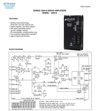
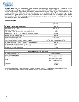
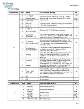
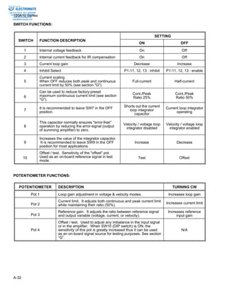

The document provides information on the 120A10 series PWM servo amplifiers from Electromate. The amplifiers are designed to drive brush DC motors and feature surface mount technology, optical isolation, and DIP switch selectable modes including current, voltage, velocity, and IR compensation. Key specifications include a 30-80V DC supply voltage, 120A peak current, 15kHz switching frequency, and 10x5.12x2.63 inch dimensions. The amplifiers have 16-pin connectors for signals and power and include features like adjustable loop gain, current limit, input gain, and offset.


