Download to read offline

![International Research Journal of Engineering and Technology (IRJET) e-ISSN: 2395 -0056
Volume: 04 Issue: 02 | Feb -2017 www.irjet.net p-ISSN: 2395-0072
© 2017, IRJET | Impact Factor value: 5.181 | ISO 9001:2008 Certified Journal | Page 1673
step would be to recognize live speech, which would
require more resources including larger speech
databases, acoustic models and exhaustive
vocabularies to produce good recognition results
REFERENCES
[1] Geoffrey Z, Picheny M (2004) Advances in large
vocabulary continuous speech recognition.AdvComput
60:249–291
[2] Carlson R (2002) Dialogue system. Slide presentation,
speech technology, GSLT,Göteborg,23Oct2002. http://
www.speech.kth.se/~rolf/gslt/GSLT021023_dialogue.
pdf
[3] Rolf C, Granström B (1997) Speech synthesis. In:
Hardcastle WJ, Laver J (eds) The handbook of phonetic
sciences. Blackwell Publishers Ltd, Oxford.
[4] He X, Deng L, Wu C (2008) Discriminative learning in
sequential pattern recognition. IEEE Signal ProcessMag
25(5):14–36](https://image.slidesharecdn.com/irjet-v4i2329-171121070042/85/Voice-Recognition-Eye-Test-3-320.jpg)

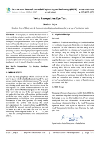
1. The document describes a voice recognition system designed to perform eye tests without needing to visit an eye doctor. It analyzes input speech using techniques like FFT and compares results to a stored dictionary to identify letters. 2. The system displays letters of decreasing size and records the user's voice responses to determine their vision accuracy compared to 20/20 vision. It integrates a microphone, filters, amplifier, and touchscreen display controlled by a PIC32 microcontroller. 3. Testing showed the system could reasonably recognize continuous speech and identify letters. Further improvements could enhance accuracy, but it provides a new option for basic eye exams without needing to leave home.