Downloaded 11 times

![Safety
Safety
WARNING
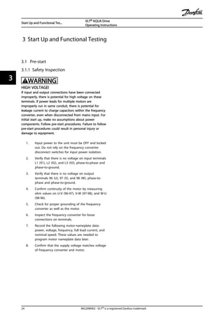
HIGH VOLTAGE!
Frequency converters contain high voltage when
connected to AC mains input power. Installation, start up,
and maintenance should be performed by qualified
personnel only. Failure to perform installation, start up, and
maintenance by qualified personnel could result in death
or serious injury.
High Voltage
Frequency converters are connected to hazardous mains
voltages. Extreme care should be taken to protect against
shock. Only trained personnel familiar with electronic
equipment should install, start, or maintain this equipment.
WARNING
UNINTENDED START!
When the frequency converter is connected to AC mains,
the motor may start at any time. The frequency converter,
motor, and any driven equipment must be in operational
readiness. Failure to be in operational readiness when the
frequency converter is connected to AC mains could result
in death, serious injury, equipment, or property damage.
Unintended Start
When the frequency converter is connected to the AC
mains, the motor may be started by means of an external
switch, a serial bus command, an input reference signal, or
a cleared fault condition. Use appropriate cautions to
guard against an unintended start.
WARNING
DISCHARGE TIME!
Frequency converters contain DC-link capacitors that can
remain charged even when the frequency converter is not
powered. To avoid electrical hazards, disconnect AC mains,
any permanent magnet type motors, and any remote DC-
link power supplies, including battery backups, UPS and
DC-link connections to other frequency converters. Wait for
the capacitors to fully discharge before performing any
service or repair work. The amount of wait time is listed in
the Discharge Time table. Failure to wait the specified time
after power has been removed before doing service or
repair could result in death or serious injury.
Voltage [V] Minimum Waiting Time (Minutes)
4 7 15
200-240 0.25-3.7 kW 5.5-45 kW
380-480 0.37-7.5 kW 11-90 kW
525-600 0.75-7.5 kW 11-90 kW
525-690 1.1-7.5 kW 11-90 kW
High voltage may be present even when the warning LED
display lights are off.
Discharge Time
Symbols
The following symbols are used in this manual.
WARNING
Indicates a potentially hazardous situation which could
result in death or serious injury.
CAUTION
Indicates a potentially hazardous situation which can result
in minor or moderate injury. It can also be used to alert
against unsafe practices.
CAUTION
Indicates a situation that could result in equipment or
property-damage-only accidents.
NOTE
Indicates highlighted information to regard with attention
to avoid mistakes or operate equipment at less than
optimal performance.
Approvals
NOTE
Imposed limitations on the output frequency
(due to export control regulations):
From software version 1.99 the output frequency of the
frequency converter is limited to 590 Hz. Software versions
1x.xx also limit the maximum output frequency to 590 Hz,
but these versions cannot be flashed, i.e. neither
downgraded nor upgraded.
Safety
VLT® AQUA Drive
Operating Instructions
MG20M902 - VLT® is a registered Danfoss trademark](https://image.slidesharecdn.com/vltaquafc202-140613202655-phpapp01/85/Vlt-aqua-fc-202-3-320.jpg)
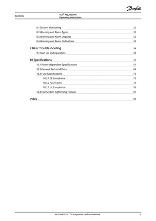
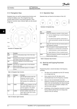
![Area Title Functions
4 DC reactors • Filter the intermediate DC
circuit voltage
• Prove line transient protection
• Reduce RMS current
• Raise the power factor
reflected back to the line
• Reduce harmonics on the AC
input
5 Capacitor bank • Stores the DC power
• Provides ride-through
protection for short power
losses
6 Inverter • Converts the DC into a
controlled PWM AC waveform
for a controlled variable
output to the motor
Area Title Functions
7 Output to motor • Regulated three-phase output
power to the motor
8 Control circuitry • Input power, internal
processing, output, and motor
current are monitored to
provide efficient operation
and control
• User interface and external
commands are monitored and
performed
• Status output and control can
be provided
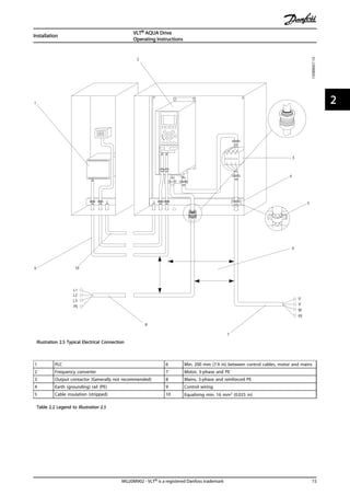
Table 1.3 Legend to Illustration 1.3
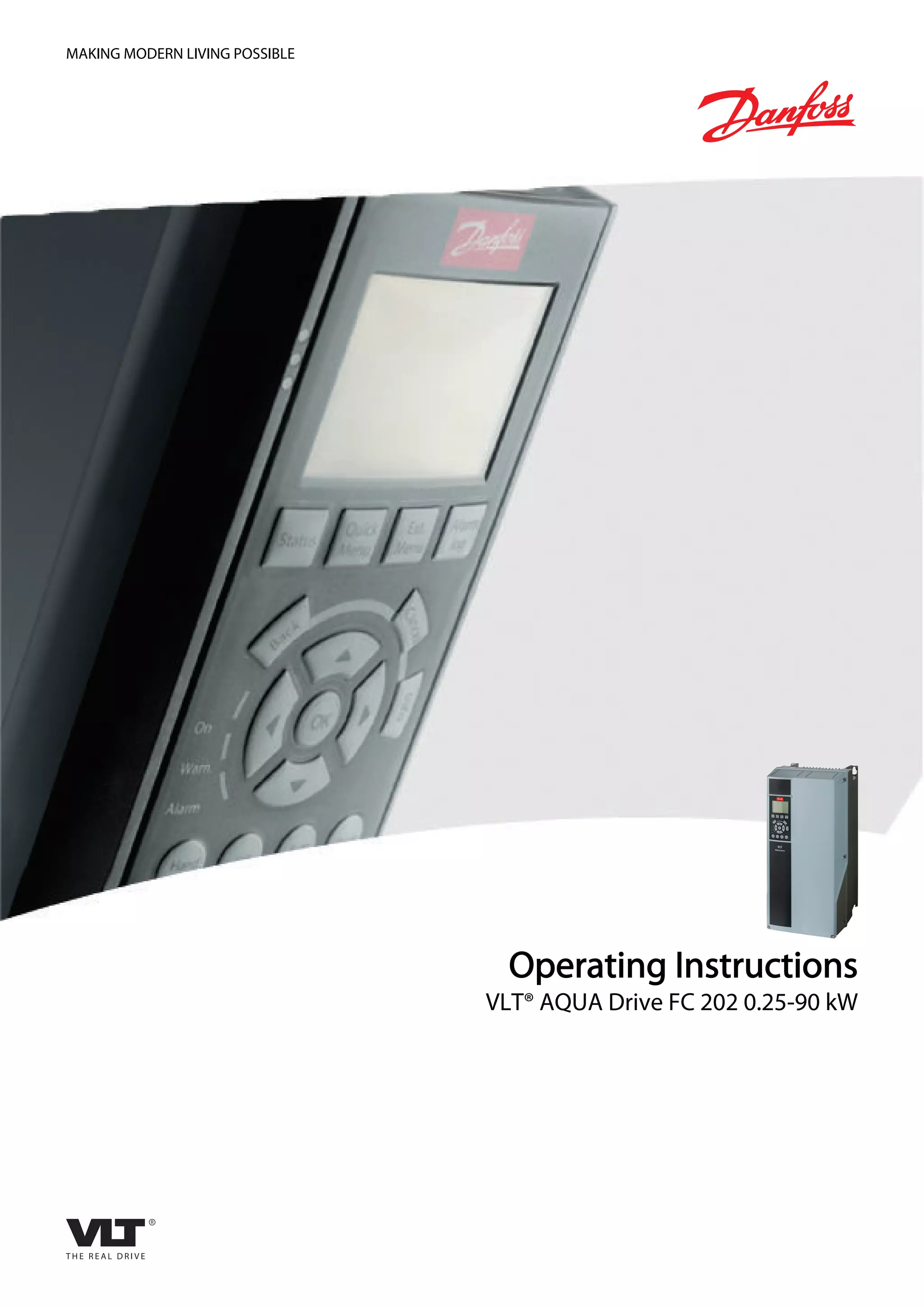
1.5 Frame Sizes and Power Ratings
References to frames sizes used in this manual are defined in Table 1.4.
Frame Size [kW]
Volts [V] A2 A3 A4 A5 B1 B2 B3 B4 C1 C2 C3 C4
200-240 0.25-2.2 3.0-3.7 0.25-2.2 0.25-3.7 5.5-11 15 5.5-11 15-18.5 18.5-30 37-45 22-30 37-45
380-480 0.37-4.0 5.5-7.5 0.37-4.0 0.37-7.5 11-18.5 22-30 11-18.5 22-37 37-55 75-90 45-55 75-90
525-600 n/a 0.75-7.5 n/a 0.75-7.5 11-18.5 22-30 11-18.5 22-37 37-55 75-90 45-55 75-90
525-690 n/a 1.1-7.5 n/a n/a n/a 11-30 n/a n/a n/a 37-90 45-55 n/a
Single phase
200-240 n/a 1.1 n/a 1.1 1.5-5.5 7.5 n/a n/a 15 22 n/a n/a
380-480 n/a n/a n/a n/a 7.5 11 n/a n/a 18.5 37 n/a n/a
Table 1.4 Frames Sizes and Power Ratings
1.6 Safe Stop
The frequency converter can perform the safety function
Safe Torque Off (STO, as defined by EN IEC 61800-5-21) and
Stop Category 0 (as defined in EN 60204-12).
Danfoss has named this functionality Safe Stop. Before
integration and use of Safe Stop in an installation, perform
a thorough risk analysis to determine whether the Safe
Stop functionality and safety levels are appropriate and
sufficient. Safe Stop is designed and approved suitable for
the requirements of:
- Safety Category 3 according to EN ISO 13849-1
- Performance Level "d" according to EN ISO
13849-1:2008
- SIL 2 Capability according to IEC 61508 and EN
61800-5-2
- SILCL 2 according to EN 62061
1) Refer to EN IEC 61800-5-2 for details of Safe torque off
(STO) function.
2) Refer to EN IEC 60204-1 for details of stop category 0
and 1.
Activation and Termination of Safe Stop
The Safe Stop (STO) function is activated by removing the
voltage at Terminal 37 of the Safe Inverter. By connecting
the Safe Inverter to external safety devices providing a safe
delay, an installation for a safe Stop Category 1 can be
obtained. The Safe Stop function can be used for
asynchronous, synchronous, and permanent magnet
motors.
WARNING
After installation of Safe Stop (STO), a commissioning test
as specified in 1.6.2 Safe Stop Commissioning Test must be
performed. A passed commissioning test is mandatory
after first installation and after each change to the safety
installation.
Safe Stop Technical Data
The following values are associated to the different types
of safety levels:
Introduction
VLT® AQUA Drive
Operating Instructions
MG20M902 - VLT® is a registered Danfoss trademark 7
1 1](https://image.slidesharecdn.com/vltaquafc202-140613202655-phpapp01/85/Vlt-aqua-fc-202-11-320.jpg)
![Safe Stop Installation and Set-Up
WARNING
SAFE STOP FUNCTION!
The safe stop function does NOT isolate mains voltage to
the frequency converter or auxiliary circuits. Perform work
on electrical parts of the frequency converter or the motor
only after isolating the mains voltage supply and waiting
the length of time specified in Table 1.1. Failure to isolate
the mains voltage supply from the unit and waiting the
time specified could result in death or serious injury.
• It is not recommended to stop the frequency
converter by using the Safe Torque Off function.
If a running frequency converter is stopped by
using the function, the unit trips and stops by
coasting. If unacceptable or dangerous, use
another stopping mode to stop the frequency
converter and machinery, before using this
function. Depending on the application, a
mechanical brake can be required.
• For synchronous and permanent magnet motor
frequency converters, in a multiple IGBT power
semiconductor failure: In spite of the activation of
the Safe Torque Off function, the system can
produce an alignment torque which maximally
rotates the motor shaft by 180/p degrees. p
denotes the pole pair number.
• This function is suitable for performing
mechanical work on the system or affected area
of a machine only. It does not provide electrical
safety. Do not use this function as a control for
starting and/or stopping the frequency converter.
Follow these steps to perform a safe installation of the
frequency converter:
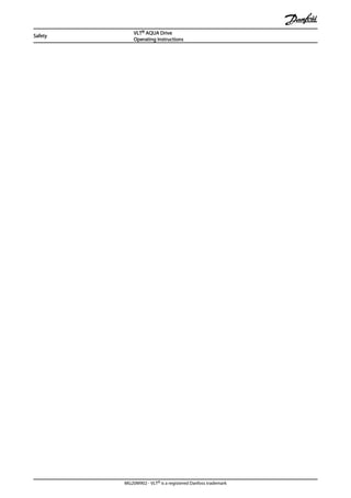
1. Remove the jumper wire between control
terminals 37 and 12 or 13. Cutting or breaking
the jumper is not sufficient to avoid short-
circuiting. (See jumper on Illustration 1.4.)
2. Connect an external Safety monitoring relay via a
NO safety function to terminal 37 (safe stop) and
either terminal 12 or 13 (24 V DC). Follow the
instruction for the safety device. The Safety
monitoring relay must comply with Category
3 /PL “d” (ISO 13849-1) or SIL 2 (EN 62061).
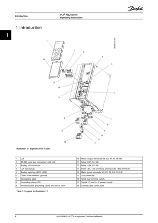
12/13 37
130BA874.10
Illustration 1.4 Jumper between Terminal 12/13 (24 V) and 37
130BC971.10
12
2
4
1
5
3
37
Illustration 1.5 Installation to Achieve a Stopping Category 0 (EN
60204-1) with Cat. 3 /PL “d” (ISO 13849-1) or SIL 2 (EN 62061).
1 Frequency converter
2 [Reset] key
3 Safety relay (cat. 3, PL d or SIL2
4 Emergency stop button
5 Short-circuit protected cable (if not inside installation IP54
cabinet)
Table 1.5 Legend to Illustration 1.5
Safe Stop Commissioning Test
After installation and before first operation, perform a
commissioning test of the installation using safe stop.
Moreover, perform the test after each modification of the
installation.
Introduction
VLT® AQUA Drive
Operating Instructions
MG20M902 - VLT® is a registered Danfoss trademark 9
1 1](https://image.slidesharecdn.com/vltaquafc202-140613202655-phpapp01/85/Vlt-aqua-fc-202-13-320.jpg)
![WARNING
Safe Stop activation (that is removal of 24 V DC voltage
supply to terminal 37) does not provide electrical safety.
The Safe Stop function itself is therefore not sufficient to
implement the Emergency-Off function as defined by EN
60204-1. Emergency-Off requires measures of electrical
isolation, for example, by switching off mains via an
additional contactor.
1. Activate the Safe Stop function by removing the
24 V DC voltage supply to the terminal 37.
2. After activation of Safe Stop (that is, after the
response time), the frequency converter coasts
(stops creating a rotational field in the motor).
The response time is typically less than 10 ms.
The frequency converter is guaranteed not to restart
creation of a rotational field by an internal fault (in
accordance with Cat. 3 PL d acc. EN ISO 13849-1 and SIL 2
acc. EN 62061). After activation of Safe Stop, the display
shows the text ”Safe Stop activated”. The associated help
text says, "Safe Stop has been activated”. This means that
the Safe Stop has been activated, or that normal operation
has not been resumed yet after Safe Stop activation.
NOTE
The requirements of Cat. 3 /PL “d” (ISO 13849-1) are only
fulfilled while 24 V DC supply to terminal 37 is kept
removed or low by a safety device which itself fulfills Cat.
3 PL “d” (ISO 13849-1). If external forces act on the motor,
it must not operate without additional measures for fall
protection. External forces can arise for example, in the
event of vertical axis (suspended loads) where an
unwanted movement, for example caused by gravity, could
cause a hazard. Fall protection measures can be additional
mechanical brakes.
By default the Safe Stop function is set to an Unintended
Restart Prevention behaviour. Therefore, to resume
operation after activation of Safe Stop,
1. reapply 24 V DC voltage to terminal 37 (text Safe
Stop activated is still displayed)
2. create a reset signal (via bus, Digital I/O, or
[Reset] key.
The Safe Stop function can be set to an Automatic Restart
behaviour. Set the value of 5-19 Terminal 37 Digital Input
from default value [1] to value [3].
Automatic Restart means that Safe Stop is terminated, and
normal operation is resumed, as soon as the 24 V DC are
applied to Terminal 37. No Reset signal is required.
WARNING
Automatic Restart Behaviour is permitted in one of the two
situations:
1. The Unintended Restart Prevention is
implemented by other parts of the Safe Stop
installation.
2. A presence in the dangerous zone can be
physically excluded when Safe Stop is not
activated. In particular, paragraph 5.3.2.5 of ISO
12100-2 2003 must be observed
1.6.2 Safe Stop Commissioning Test
After installation and before first operation, perform a
commissioning test of an installation or application, using
Safe Stop.
Perform the test again after each modification of the
installation or application involving the Safe Stop.
NOTE
A passed commissioning test is mandatory after first instal-
lation and after each change to the safety installation.
The commissioning test (select one of cases 1 or 2 as
applicable):
Case 1: Restart prevention for Safe Stop is required (that is
Safe Stop only where 5-19 Terminal 37 Digital Input is set
to default value [1], or combined Safe Stop and MCB 112
where 5-19 Terminal 37 Digital Input is set to [6] PTC 1 &
Relay A or [9] PTC 1 & Relay W/A):
1.1 Remove the 24 V DC voltage supply to
terminal 37 using the interrupt device while the
frequency converter drives the motor (that is
mains supply is not interrupted). The test step is
passed when
• the motor reacts with a coast, and
• the mechanical brake is activated (if
connected)
• the alarm “Safe Stop [A68]” is displayed
in the LCP, if mounted
1.2 Send Reset signal (via Bus, Digital I/O, or
[Reset] key). The test step is passed if the motor
remains in the Safe Stop state, and the
mechanical brake (if connected) remains
activated.
1.3 Reapply 24 V DC to terminal 37. The test step
is passed if the motor remains in the coasted
state, and the mechanical brake (if connected)
remains activated.
Introduction
VLT® AQUA Drive
Operating Instructions
10 MG20M902 - VLT® is a registered Danfoss trademark
11](https://image.slidesharecdn.com/vltaquafc202-140613202655-phpapp01/85/Vlt-aqua-fc-202-14-320.jpg)
![1.4 Send Reset signal (via Bus, Digital I/O, or
[Reset] key). The test step is passed when the
motor becomes operational again.
The commissioning test is passed if all four test steps 1.1,
1.2, 1.3 and 1.4 are passed.
Case 2: Automatic Restart of Safe Stop is wanted and
allowed (that is, Safe Stop only where 5-19 Terminal 37
Digital Input is set to [3], or combined Safe Stop and MCB
112 where 5-19 Terminal 37 Digital Input is set to [7] PTC 1
& Relay W or [8] PTC 1 & Relay A/W):
2.1 Remove the 24 V DC voltage supply to
terminal 37 by the interrupt device while the
frequency converter drives the motor (that is
mains supply is not interrupted). The test step is
passed when
• the motor reacts with a coast, and
• the mechanical brake is activated (if
connected)
• the alarm “Safe Stop [A68]” is displayed
in the LCP, if mounted
2.2 Reapply 24 V DC to terminal 37.
The test step is passed if the motor becomes operational
again. The commissioning test is passed if both test steps
2.1 and 2.2 are passed.
NOTE
See warning on the restart behaviour in 1.6.1 Terminal 37
Safe Stop Function
WARNING
The Safe Stop function can be used for asynchronous,
synchronous and permanent magnet motors. Two faults
can occur in the power semiconductor of the frequency
converter. When using synchronous or permanent magnet
motors a residual rotation can result from the faults. The
rotation can be calculated to Angle = 360/(Number of
Poles). The application using synchronous or permanent
magnet motors must take this residual rotation into
consideration and ensure that it does not pose a safety
risk. This situation is not relevant for asynchronous motors.
Introduction
VLT® AQUA Drive
Operating Instructions
MG20M902 - VLT® is a registered Danfoss trademark 11
1 1](https://image.slidesharecdn.com/vltaquafc202-140613202655-phpapp01/85/Vlt-aqua-fc-202-15-320.jpg)
![a
b
130BA419.10
Illustration 2.1 Top and Bottom Cooling Clearance
Enclosure A2-A5 B1-B4 C1, C3 C2, C4
a/b [mm] 100 200 200 225
Table 2.1 Minimum Airflow Clearance Requirements
2.3.2 Lifting
• Check the weight of the unit to determine a safe
lifting method
• Ensure that the lifting device is suitable for the
task
• If necessary, plan for a hoist, crane, or forklift with
the appropriate rating to move the unit
• For lifting, use hoist rings on the unit, when
provided
2.3.3 Mounting
• Mount the unit vertically
• The frequency converter allows side by side
installation
• Ensure that the strength of the mounting location
will support the unit weight
• Mount the unit to a solid flat surface or to the
optional back plate to provide cooling airflow
(see Illustration 2.2 and Illustration 2.3)
• Improper mounting can result in over heating
and reduced performance
• Use the slotted mounting holes on the unit for
wall mounting, when provided
130BA219.10
A
Illustration 2.2 Proper Mounting with Back Plate
Item A is a back plate properly installed for required
airflow to cool the unit.
130BA228.10
A
Illustration 2.3 Proper Mounting with Railings
NOTE
Back plate is needed when mounted on railings.
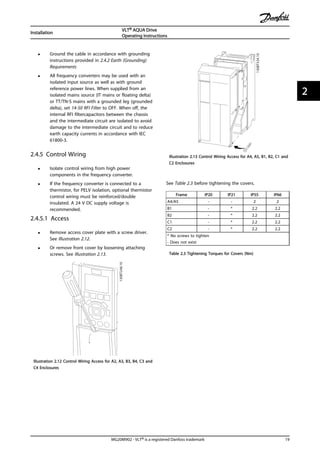
2.3.4 Tightening Torques
See 10.4 Connection Tightening Torques for proper
tightening specifications.
Installation
VLT® AQUA Drive
Operating Instructions
MG20M902 - VLT® is a registered Danfoss trademark 13
2 2](https://image.slidesharecdn.com/vltaquafc202-140613202655-phpapp01/85/Vlt-aqua-fc-202-17-320.jpg)
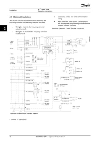
![2.4.5.2 Control Terminal Types
Illustration 2.17 shows the removable frequency converter
connectors. Terminal functions and default settings are
summarized in Table 2.4.
1
4
2
3
130BA012.11
61
68 69
39
42
50
53 54 55
12
13
18
19
27
29
32
33
20
37
Illustration 2.14 Control Terminal Locations
• Connector 1 provides four programmable digital
inputs terminals, two additional digital terminals
programmable as either input or output, a 24V
DC terminal supply voltage, and a common for
optional customer supplied 24 V DC voltage
• Connector 2 terminals (+)68 and (-)69 are for an
RS-485 serial communications connection
• Connector 3 provides two analog inputs, one
analog output, 10V DC supply voltage, and
commons for the inputs and output
• Connector 4 is a USB port available for use with
the MCT 10 Set-up Software
• Also provided are two Form C relay outputs that
are in various locations depending upon the
frequency converter configuration and size
• Some options available for ordering with the unit
may provide additional terminals. See the manual
provided with the equipment option.
See 10.2 General Technical Data for terminal ratings details.
Terminal Description
Digital Inputs/Outputs
Terminal Parameter
Default
Setting Description
12, 13 - +24 V DC 24 V DC supply
voltage. Maximum
output current is 200
mA total for all 24 V
loads. Useable for
digital inputs and
external transducers.
18 5-10 [8] Start
Digital inputs.
19 5-11 [0] No
operation
32 5-14 [0] No
operation
33 5-15 [0] No
operation
27 5-12 [2] Coast
inverse
Selectable for either
digital input or
output. Default setting
is input.
29 5-13 [14] JOG
20 - Common for digital
inputs and 0 V
potential for 24 V
supply.
37 - Safe Torque
Off (STO)
(optional) Safe input.
Used for STO.
Analog Inputs/Outputs
39 - Common for analog
output
42 6-50 Speed 0 -
High Limit
Programmable analog
output. The analog
signal is 0-20mA or
4-20 mA at a
maximum of 500Ω
50 - +10 V DC 10 V DC analog
supply voltage. 15 mA
maximum commonly
used for potenti-
ometer or thermistor.
53 6-1 Reference Analog input.
Selectable for voltage
or current. Switches
A53 and A54 select
mA or V.
54 6-2 Feedback
55 - Common for analog
input
Serial Communication
61 - Integrated RC-Filter
for cable screen. ONLY
for connecting the
screen when experi-
encing EMC problems.
Installation
VLT® AQUA Drive
Operating Instructions
20 MG20M902 - VLT® is a registered Danfoss trademark
22](https://image.slidesharecdn.com/vltaquafc202-140613202655-phpapp01/85/Vlt-aqua-fc-202-24-320.jpg)
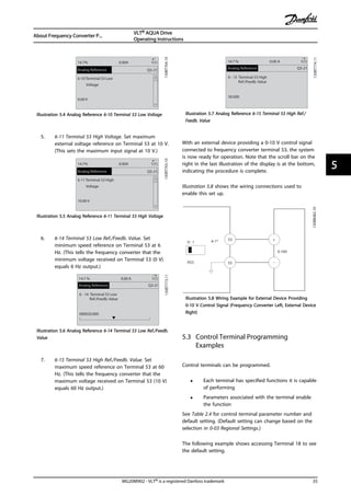
![Terminal Description
Digital Inputs/Outputs
Terminal Parameter
Default
Setting Description
68 (+) 8-3 RS-485 Interface. A
control card switch is
provided for
termination resistance.
69 (-) 8-3
Relays
01, 02, 03 5-40 [0] [0] Alarm Form C relay output.
Usable for AC or DC
voltage and resistive
or inductive loads.
04, 05, 06 5-40 [1] [0] Running
Table 2.4 Terminal Description
2.4.5.3 Wiring to Control Terminals
Control terminal connectors can be unplugged from the
frequency converter for ease of installation, as shown in
Illustration 2.15.
130BT306.10
Illustration 2.15 Unplugging Control Terminals
1. Open the contact by inserting a small screwdriver
into the slot above or below the contact, as
shown in Illustration 2.16.
2. Insert the bared control wire into the contact.
3. Remove the screwdriver to fasten the control wire
into the contact.
4. Ensure the contact is firmly established and not
loose. Loose control wiring can be the source of
equipment faults or less than optimal operation.
See 10.1 Power-dependent Specifications for control terminal
wiring sizes.
See 6 Application Set Up Examples for typical control wiring
connections.
2
1
10mm
130BA310.10
12 13 18 19 27 29 32 33
Illustration 2.16 Connecting Control Wiring
2.4.5.4 Using Screened Control Cables
Correct screening
The preferred method in most cases is to secure control
and serial communication cables with screening clamps
provided at both ends to ensure best possible high
frequency cable contact.
PE
FC
PE
PLC
130BB610.11
Illustration 2.17 Screening Clamps at Both Ends
50/60 Hz ground loops
With very long control cables, ground loops may occur. To
eliminate ground loops, connect one end of the screen-to-
ground with a 100 nF capacitor (keeping leads short).
100nF
FC
PE
PE
PLC
130BB609.11
Illustration 2.18 Connection with a 100 nF Capacitor
Avoid EMC noise on serial communication
To eliminate low-frequency noise between frequency
converters, connect one end of the screen to terminal 61.
This terminal is connected to ground via an internal RC
link. Use twisted-pair cables to reduce interference
between conductors.
- 69
FC
+68
61 (PE)
FC
PE
130BB611.11
Illustration 2.19 Twisted-pair Cables
Installation
VLT® AQUA Drive
Operating Instructions
MG20M902 - VLT® is a registered Danfoss trademark 21
2 2](https://image.slidesharecdn.com/vltaquafc202-140613202655-phpapp01/85/Vlt-aqua-fc-202-25-320.jpg)
![2.4.5.5 Control Terminal Functions
Frequency converter functions are commanded by
receiving control input signals.
• Each terminal must be programmed for the
function it will be supporting in the parameters
associated with that terminal. See Table 2.4 for
terminals and associated parameters.
• It is important to confirm that the control
terminal is programmed for the correct function.
See 4 User Interface for details on accessing
parameters and 5 About Frequency Converter
Programming for details on programming.
• The default terminal programming is intended to
initiate frequency converter functioning in a
typical operational mode.
2.4.5.6 Jumper Terminals 12 and 27
A jumper wire may be required between terminal 12 (or
13) and terminal 27 for the frequency converter to operate
when using factory default programming values.
• Digital input terminal 27 is designed to receive a
24 V DC external interlock command. In many
applications, the user wires an external interlock
device to terminal 27
• When no interlock device is used, wire a jumper
between control terminal 12 (recommended) or
13 to terminal 27. This provides in internal 24 V
signal on terminal 27
• No signal present prevents the unit from
operating
• When the status line at the bottom of the LCP
reads AUTO REMOTE COASTING or Alarm 60
External Interlock is displayed, this indicates that
the unit is ready to operate but is missing an
input signal on terminal 27.
• When factory installed optional equipment is
wired to terminal 27, do not remove that wiring.
2.4.5.7 Terminal 53 and 54 Switches
• Analog input terminals 53 and 54 can select
either voltage (0 to 10 V) or current (0/4-20 mA)
input signals
• Remove power to the frequency converter before
changing switch positions
• Set switches A53 and A54 to select the signal
type. U selects voltage, I selects current.
• The switches are accessible when the LCP has
been removed (see Illustration 2.20). Note that
some option cards available for the unit may
cover these switches and must be removed to
change switch settings. Always remove power to
the unit before removing option cards.
• Terminal 53 default is for a speed reference signal
in open loop set in 16-61 Terminal 53 Switch
Setting
• Terminal 54 default is for a feedback signal in
closed loop set in 16-63 Terminal 54 Switch Setting
130BT310.10
12
NO
VLT
BUS TER.
OFF-ON
A53 A54
U- I U- I
Illustration 2.20 Location of Terminals 53 and 54 Switches
2.4.5.8 Mechanical Brake Control
In hoisting/lowering applications, it is necessary to be able
to control an electro-mechanical brake:
• Control the brake using any relay output or
digital output (terminal 27 or 29).
• Keep the output closed (voltage-free) as long as
the frequency converter is unable to ‘support’ the
motor, for example due to the load being too
heavy.
• Select [32] Mechanical brake control in parameter
group 5-4* Relays for applications with an electro-
mechanical brake.
• The brake is released when the motor current
exceeds the preset value in 2-20 Release Brake
Current.
• The brake is engaged when the output frequency
is less than the frequency set in 2-21 Activate
Brake Speed [RPM] or 2-22 Activate Brake Speed
Installation
VLT® AQUA Drive
Operating Instructions
22 MG20M902 - VLT® is a registered Danfoss trademark
22](https://image.slidesharecdn.com/vltaquafc202-140613202655-phpapp01/85/Vlt-aqua-fc-202-26-320.jpg)
![[Hz], and only if the frequency converter carries
out a stop command.
If the frequency converter is in alarm mode or in an over-
voltage situation, the mechanical brake immediately cuts
in.
In the vertical movement, the key point is that the load
must be held, stopped, controlled (raised, lowered) in a
safe mode during the entire operation. Because the
frequency converter is not a safety device, the crane/lift
designer (OEM) must decide on the type and number of
safety devices (e.g. speed switch, emergency brakes etc.) to
be used, in order to be able to stop the load in case of
emergency or malfunction of the system, according to
relevant national crane/lift regulations.
L1 L2 L3
U V W
02 01
A1
A2
130BA902.10
Drive
Output
relay
Command Circuit
220Vac
Mechanical
Brake
ShaftMotor
Frewheeling
diode
Brake
380Vac
Output
Contactor
Input
Power Circuit
Illustration 2.21 Connecting the Mechanical Brake to the
Frequency Converter
2.4.6 Serial Communication
Connect RS-485 serial communication wiring to terminals
(+)68 and (-)69.
• Screened serial communication cable is
recommended
• See 2.4.2 Earth (Grounding) Requirements for
proper grounding
61
68
69
+
130BB489.10
RS-485
Illustration 2.22 Serial Communication Wiring Diagram
For basic serial communication set up, select the following
1. Protocol type in 8-30 Protocol.
2. Frequency converter address in 8-31 Address.
3. Baud rate in 8-32 Baud Rate.
• Four communication protocols are internal to the
frequency converter. Follow motor manufacturer
wiring requirements.
Danfoss FC
Modbus RTU
Johnson Controls N2®
• Functions can be programmed remotely using
the protocol software and RS-485 connection or
in parameter group 8-** Communications and
Options
• Selecting a specific communication protocol
changes various default parameter settings to
match that protocol’s specifications along with
making additional protocol-specific parameters
available
• Option cards for the frequency converter are
available to provide additional communication
protocols. See the option-card documentation for
installation and operation instructions
Installation
VLT® AQUA Drive
Operating Instructions
MG20M902 - VLT® is a registered Danfoss trademark 23
2 2](https://image.slidesharecdn.com/vltaquafc202-140613202655-phpapp01/85/Vlt-aqua-fc-202-27-320.jpg)
![3.2 Applying Power to the Frequency
Converter
WARNING
HIGH VOLTAGE!
Frequency converters contain high voltage when
connected to AC mains. Installation, start-up and
maintenance should be performed by qualified personnel
only. Failure to comply could result in death or serious
injury.
WARNING
UNINTENDED START!
When the frequency converter is connected to AC mains,
the motor may start at any time. The frequency converter,
motor, and any driven equipment must be in operational
readiness. Failure to comply could result in death, serious
injury, equipment, or property damage.
1. Confirm that the input voltage is balanced within
3%. If not, correct input voltage imbalance before
proceeding. Repeat this procedure after the
voltage correction.
2. Ensure that optional equipment wiring, if present,
matches the installation application.
3. Ensure that all operator devices are in the OFF
position. Panel doors should be closed or cover
mounted.
4. Apply power to the unit. DO NOT start the
frequency converter at this time. For units with a
disconnect switch, turn to the ON position to
apply power to the frequency converter.
NOTE
If the status line at the bottom of the LCP reads AUTO
REMOTE COASTING or Alarm 60 External Interlock is
displayed, this indicates that the unit is ready to operate
but is missing an input signal on terminal 27. See
Illustration 1.4 for details.
3.3 Basic Operational Programming
3.3.1 Required Initial Frequency Converter
Programming
Frequency converters require basic operational
programming before running for best performance. Basic
operational programming requires entering motor-
nameplate data for the motor being operated and the
minimum and maximum motor speeds. Enter data in
accordance with the following procedure. Parameter
settings recommended are intended for start up and
checkout purposes. Application settings may vary. See
4 User Interface for detailed instructions on entering data
through the LCP.
Enter data with power ON, but before operating the
frequency converter.
1. Press [Main Menu] twice on the LCP.
2. Use the navigation keys to scroll to parameter
group 0-** Operation/Display and press [OK].
130BP066.10
1107 RPM
0 - ** Operation/Display
1 - ** Load/Motor
2 - ** Brakes
3 - ** Reference / Ramps
3.84 A 1 (1)
Main menu
Illustration 3.1 Main Menu
3. Use navigation keys to scroll to parameter group
0-0* Basic Settings and press [OK].
0-**Operation / Display
0.0%
0-0*Basic Settings
0-1*Set-up Opperations
0-2*LCP Display
0-3*LCP Custom Readout
0.00A 1(1)
130BP087.10
Illustration 3.2 Operation/Display
4. Use navigation keys to scroll to 0-03 Regional
Settings and press [OK].
0-0*Basic Settings
0.0%
0-03 Regional Settings
[0] International
0.00A 1(1)
130BP088.10
Illustration 3.3 Basic Settings
5. Use navigation keys to select [0] International or
[1] North America as appropriate and press [OK].
(This changes the default settings for a number
of basic parameters. See 5.4 International/North
American Default Parameter Settings for a
complete list.)
6. Press [Quick Menu] on the LCP.
Start Up and Functional Tes...
VLT® AQUA Drive
Operating Instructions
26 MG20M902 - VLT® is a registered Danfoss trademark
33](https://image.slidesharecdn.com/vltaquafc202-140613202655-phpapp01/85/Vlt-aqua-fc-202-30-320.jpg)
![7. Use the navigation keys to scroll to parameter
group Q2 Quick Setup and press [OK].
130BB847.10
Q1 My Personal Menu
Q2 Quick Setup
Q5 Changes Made
Q6 Loggings
13.7% 13.0A 1(1)
Quick Menus
Illustration 3.4 Quick Menus
8. Select language and press [OK].
9. A jumper wire should be in place between
control terminals 12 and 27. If this is the case,
leave 5-12 Terminal 27 Digital Input at factory
default. Otherwise select No Operation. For
frequency converters with an optional Danfoss
bypass, no jumper wire is required.
10. 3-02 Minimum Reference
11. 3-03 Maximum Reference
12. 3-41 Ramp 1 Ramp Up Time
13. 3-42 Ramp 1 Ramp Down Time
14. 3-13 Reference Site. Linked to Hand/Auto* Local
Remote.
3.4 PM Motor Setup in VVCplus
CAUTION
Do only use PM motor with fans and pumps.
Initial Programming Steps
1. Activate PM motor operation 1-10 Motor
Construction, select [1) PM, non salient SPM
2. Make sure to set 0-02 Motor Speed Unit to [0] RPM
Programming motor data.
After selecting PM motor in 1-10 Motor Construction, the
PM motor-related parameters in parameter groups 1-2*,
1-3* and 1-4* are active.
The information can be found on the motor nameplate
and in the motor data sheet.
Following parameters must be programmed in the listed
order
1. 1-24 Motor Current
2. 1-26 Motor Cont. Rated Torque
3. 1-25 Motor Nominal Speed
4. 1-39 Motor Poles
5. 1-30 Stator Resistance (Rs)
Enter line to common stator winding resistance
(Rs). If only line-line data are available, divide the
line-line value with 2 to achieve the line to
common (starpoint) value.
It is also possible to measure the value with an
ohmmeter, which will also take the resistance of
the cable into account. Divide the measured
value by 2 and enter the result.
6. 1-37 d-axis Inductance (Ld)
Enter line to common direct axis inductance of
the PM motor.
If only line-line data are available, divide the line-
line value with 2 to achieve the line-common
(starpoint) value.
It is also possible to measure the value with an
inductancemeter, which will also take the
inductance of the cable into account. Divide the
measured value by 2 and enter the result.
7. 1-40 Back EMF at 1000 RPM
Enter line to line back EMF of PM Motor at 1000
RPM mechanical speed (RMS value). Back EMF is
the voltage generated by a PM motor when no
drive is connected and the shaft is turned
externally. Back EMF is normally specified for
nominal motor speed or for 1000 RPM measured
between two lines. If the value is not available for
a motor speed of 1000 RPM, calculate the correct
value as follows: If back EMF is e.g. 320 V at 1800
RPM, it can be calculated at 1000 RPM as follows:
Back EMF= (Voltage / RPM)*1000 =
(320/1800)*1000 = 178. This is the value that
must be programmed for 1-40 Back EMF at 1000
RPM
Test Motor Operation
1. Start the motor at low speed (100 to 200 RPM). If
the motor does not turn, check installation,
general programming and motor data.
2. Check if start function in 1-70 PM Start Mode fits
the application requirements.
Rotor detection
This function is the recommended choice for applications
where the motor starts from standstill e.g. pumps or
conveyors. On some motors, an acoustic sound is heard
when the impulse is sent out. This does not harm the
motor.
Parking
This function is the recommended choice for applications
where the motor is rotating at slow speed eg. windmilling
in fan applications. 2-06 Parking Current and 2-07 Parking
Time can be adjusted. Increase the factory setting of these
parameters for applications with high inertia.
Start the motor at nominal speed. In case the application
does not run well, check the VVCplus PM settings.
Start Up and Functional Tes...
VLT® AQUA Drive
Operating Instructions
MG20M902 - VLT® is a registered Danfoss trademark 27
3 3](https://image.slidesharecdn.com/vltaquafc202-140613202655-phpapp01/85/Vlt-aqua-fc-202-31-320.jpg)
![Recommendations in different applications can be seen in
Table 3.2.
Application Settings
Low inertia applications
ILoad/IMotor <5
1-17 Voltage filter time const. to be
increased by factor 5 to 10
1-14 Damping Gain should be
reduced
1-66 Min. Current at Low Speed
should be reduced (<100%)
Low inertia applications
50>ILoad/IMotor >5
Keep calculated values
High inertia applications
ILoad/IMotor > 50
1-14 Damping Gain, 1-15 Low Speed
Filter Time Const. and 1-16 High
Speed Filter Time Const. should be
increased
High load at low speed
<30% (rated speed)
1-17 Voltage filter time const. should
be increased
1-66 Min. Current at Low Speed
should be increased (>100% for
longer time can overheat the motor)
Table 3.2 Recommendations in Different Applications
If the motor starts oscillating at a certain speed, increase
1-14 Damping Gain. Increase the value in small steps.
Depending on the motor, a good value for this parameter
can be 10% or 100% higher than the default value.
Starting torque can be adjusted in 1-66 Min. Current at Low
Speed. 100% provides nominal torque as starting torque.
3.5 Automatic Motor Adaptation
Automatic motor adaptation (AMA) is a test procedure that
measures the electrical characteristics of the motor to
optimize compatibility between the frequency converter
and the motor.
• The frequency converter builds a mathematical
model of the motor for regulating output motor
current. The procedure also tests the input phase
balance of electrical power. It compares the
motor characteristics with the data entered in
parameters 1-20 to 1-25.
• It does not cause the motor to run or harm to
the motor
• Some motors may be unable to run the complete
version of the test. In that case, select [2] Enable
reduced AMA
• If an output filter is connected to the motor,
select Enable reduced AMA
• If warnings or alarms occur, see 8 Warnings and
Alarms
• Run this procedure on a cold motor for best
results
NOTE
The AMA algorithm does not work when using PM motors.
To run AMA
1. Press [Main Menu] to access parameters.
2. Scroll to parameter group 1-** Load and Motor.
3. Press [OK].
4. Scroll to parameter group 1-2* Motor Data.
5. Press [OK].
6. Scroll to 1-29 Automatic Motor Adaptation (AMA).
7. Press [OK].
8. Select [1] Enable complete AMA.
9. Press [OK].
10. Follow on-screen instructions.
11. The test will run automatically and indicate when
it is complete.
3.6 Check Motor Rotation
Before running the frequency converter, check the motor
rotation. The motor will run briefly at 5 Hz or the
minimum frequency set in 4-12 Motor Speed Low Limit [Hz].
1. Press [Main Menu].
2. Press [OK].
3. Navigate to 1-28 Motor Rotation Check.
4. Press [OK].
5. Scroll to [1] Enable.
The following text will appear: Note! Motor may run in
wrong direction.
6. Press [OK].
7. Follow the on-screen instructions.
To change the direction of rotation, remove power to the
frequency converter and wait for power to discharge.
Reverse the connection of any two of the three motor
cables on the motor or frequency converter side of the
connection.
Start Up and Functional Tes...
VLT® AQUA Drive
Operating Instructions
28 MG20M902 - VLT® is a registered Danfoss trademark
33](https://image.slidesharecdn.com/vltaquafc202-140613202655-phpapp01/85/Vlt-aqua-fc-202-32-320.jpg)
![3.7 Local-control Test
CAUTION
MOTOR START!
Ensure that the motor, system and any attached
equipment are ready for start. It is the responsibility of the
user to ensure safe operation under any condition. Failure
to ensure that the motor, system, and any attached
equipment is ready for start could result in personal injury
or equipment damage.
NOTE
The [Hand On] key provides a local start command to the
frequency converter. The [Off] key provides the stop
function.
When operating in local mode, [▲] and [▼] increase and
decrease the speed output of the frequency converter. [◄]
and [►] move the display cursor in the numeric display.
1. Press [Hand On].
2. Accelerate the frequency converter by pressing
[▲] to full speed. Moving the cursor left of the
decimal point provides quicker input changes.
3. Note any acceleration problems.
4. Press [Off].
5. Note any deceleration problems.
If acceleration problems were encountered
• If warnings or alarms occur, see 8 Warnings and
Alarms
• Check that motor data is entered correctly
• Increase the ramp-up time in 3-41 Ramp 1 Ramp
Up Time
• Increase current limit in 4-18 Current Limit
• Increase torque limit in 4-16 Torque Limit Motor
Mode
If deceleration problems were encountered
• If warnings or alarms occur, see 8 Warnings and
Alarms.
• Check that motor data is entered correctly.
• Increase the ramp-down time in 3-42 Ramp 1
Ramp Down Time.
• Enable overvoltage control in 2-17 Over-voltage
Control.
See 4.1.1 Local Control Panel for resetting the frequency
converter after a trip.
NOTE
3.2 Applying Power to the Frequency Converter to 3.3 Basic
Operational Programming conclude the procedures for
applying power to the frequency converter, basic
programming, set-up and functional testing.
3.8 System Start Up
The procedure in this section requires user-wiring and
application programming to be completed. 6 Application
Set Up Examples is intended to help with this task. Other
aids to application set-up are listed in 1.2 Additional
Resources. The following procedure is recommended after
application set-up by the user is completed.
CAUTION
MOTOR START!
Ensure that the motor, system and any attached
equipment is ready for start. It is the responsibility of the
user to ensure safe operation under any condition. Failure
to do so could result in personal injury or equipment
damage.
1. Press [Auto On].
2. Ensure that external control functions are
properly wired to the frequency converter and all
programming is completed.
3. Apply an external run command.
4. Adjust the speed reference> throughout the
speed range.
5. Remove the external run command.
6. Note any problems.
If warnings or alarms occur, see 8 Warnings and Alarms.
3.9 Acoustic Noise or Vibration
If the motor or the equipment driven by the motor - e.g. a
fan blade - is making noise or vibrations at certain
frequencies, try the following:
• Speed Bypass, parameter group 4-6*
• Over-modulation, 14-03 Overmodulation set to off
• Switching pattern and switching frequency
parameter group 14-0*
• Resonance Dampening, 1-64 Resonance
Dampening
Start Up and Functional Tes...
VLT® AQUA Drive
Operating Instructions
MG20M902 - VLT® is a registered Danfoss trademark 29
3 3](https://image.slidesharecdn.com/vltaquafc202-140613202655-phpapp01/85/Vlt-aqua-fc-202-33-320.jpg)
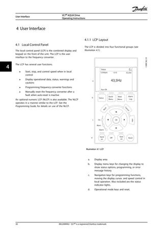
![4.1.2 Setting LCP Display Values
The display area is activated when the frequency converter
receives power from mains voltage, a DC bus terminal, or
an external 24 V DC supply.
The information displayed on the LCP can be customized
for user application.
• Each display readout has a parameter associated
with it
• Options are selected in the quick menu Q3-13
Display Settings
• Display 2 has an alternate larger display option
• The frequency converter status at the bottom line
of the display is generated automatically and is
not selectable
1.1
2
3 1.3
1.2
130BP041.10
799 RPM
Auto Remote Ramping
1 (1)
36.4 kw7.83 A
0.000
53.2 %
Status
Illustration 4.2 Display Readouts
1.1
1.2
2
1.3
130BP062.10
207RPM
Auto Remote Running
1 (1)
24.4 kW5.25A
6.9Hz
Status
Illustration 4.3 Display Readouts
Display Parameter number Default setting
1.1 0-20 Motor RPMs
1.2 0-21 Motor current
1.3 0-22 Motor power (kW)
2 0-23 Motor frequency
3 0-24 Reference in percent
Table 4.1 Legend to Illustration 4.2 and Illustration 4.3
4.1.3 Display Menu Keys
Menu keys are used for menu access for parameter set-up,
toggling through status display modes during normal
operation, and viewing fault log data.
130BP045.10
Status
Quick
Menu
Main
Menu
Alarm
Log
Illustration 4.4 Menu Keys
Key Function
Status Shows operational information.
• In Auto mode, press to toggle between
status read-out displays
• Press repeatedly to scroll through each
status display
• Press [Status] plus [▲] or [▼] to adjust the
display brightness
• The symbol in the upper right corner of the
display shows the direction of motor
rotation and which set-up is active. This is
not programmable.
Quick Menu Allows access to programming parameters for
initial set up instructions and many detailed
application instructions.
• Press to access Q2 Quick Setup for
sequenced instructions to program the basic
frequency controller set up
• Follow the sequence of parameters as
presented for the function set up
Main Menu Allows access to all programming parameters.
• Press twice to access top-level index
• Press once to return to the last location
accessed
• Press to enter a parameter number for
direct access to that parameter
Alarm Log Displays a list of current warnings, the last 10
alarms, and the maintenance log.
• For details about the frequency converter
before it entered the alarm mode, select the
alarm number using the navigation keys
and press [OK].
Table 4.2 Function Description Menu Keys
User Interface
VLT® AQUA Drive
Operating Instructions
MG20M902 - VLT® is a registered Danfoss trademark 31
4 4](https://image.slidesharecdn.com/vltaquafc202-140613202655-phpapp01/85/Vlt-aqua-fc-202-35-320.jpg)
![WARNING
UNINTENDED START!
When the frequency converter is connected to AC mains,
the motor may start at any time. The frequency converter,
motor, and any driven equipment must be in operational
readiness. Failure to be in operational readiness when the
frequency converter is connected to AC mains could result
in death, serious injury, or equipment or property damage.
4.2.1 Uploading Data to the LCP
1. Press [Off] to stop the motor before uploading or
downloading data.
2. Go to 0-50 LCP Copy.
3. Press [OK].
4. Select All to LCP.
5. Press [OK]. A progress bar shows the uploading
process.
6. Press [Hand On] or [Auto On] to return to normal
operation.
4.2.2 Downloading Data from the LCP
1. Press [Off] to stop the motor before uploading or
downloading data.
2. Go to 0-50 LCP Copy.
3. Press [OK].
4. Select All from LCP.
5. Press [OK]. A progress bar shows the
downloading process.
6. Press [Hand On] or [Auto On] to return to normal
operation.
4.3 Restoring Default Settings
CAUTION
Initialisation restores the unit to factory default settings.
Any programming, motor data, localization, and
monitoring records will be lost. Uploading data to the LCP
provides a backup before initialisation.
Restoring the frequency converter parameter settings back
to default values is done by initialisation of the frequency
converter. Initialisation can be through 14-22 Operation
Mode or manually.
• Initialisation using 14-22 Operation Mode does not
change frequency converter data such as
operating hours, serial communication selections,
personal menu settings, fault log, alarm log, and
other monitoring functions
• Using 14-22 Operation Mode is generally
recommended
• Manual initialisation erases all motor,
programming, localization, and monitoring data
and restores factory default settings
4.3.1 Recommended Initialisation
1. Press [Main Menu] twice to access parameters.
2. Scroll to 14-22 Operation Mode.
3. Press [OK].
4. Scroll to Initialisation.
5. Press [OK].
6. Remove power to the unit and wait for the
display to turn off.
7. Apply power to the unit.
Default parameter settings are restored during start up.
This may take slightly longer than normal.
8. Alarm 80 is displayed.
9. Press [Reset] to return to operation mode.
4.3.2 Manual Initialisation
1. Remove power to the unit and wait for the
display to turn off.
2. Press and hold [Status], [Main Menu], and [OK] at
the same time and apply power to the unit.
Factory default parameter settings are restored during start
up. This may take slightly longer than normal.
Manual initialisation does not reset the following frequency
converter information
• 15-00 Operating Hours
• 15-03 Power Up's
• 15-04 Over Temp's
• 15-05 Over Volt's
User Interface
VLT® AQUA Drive
Operating Instructions
MG20M902 - VLT® is a registered Danfoss trademark 33
4 4](https://image.slidesharecdn.com/vltaquafc202-140613202655-phpapp01/85/Vlt-aqua-fc-202-37-320.jpg)
![5 About Frequency Converter Programming
5.1 Introduction
The frequency converter is programmed for its application
functions using parameters. Parameters are accessed by
pressing either [Quick Menu] or [Main Menu] on the LCP.
(See 4 User Interface for details on using the LCP function
keys.) Parameters may also be accessed through a PC
using the MCT 10 Set-up Software (see )5.6 Remote
Programming with MCT 10 Set-up Software.
The quick menu is intended for initial start up(Q2-** Quick
Set Up) and detailed instructions for common frequency
converter applications (Q3-** Function Set Up). Step-by-step
instructions are provided. These instructions enable the
user to walk through the parameters used for
programming applications in their proper sequence. Data
entered in a parameter can change the options available in
the parameters following that entry. The quick menu
presents easy guidelines for getting most systems up and
running.
The Quick Menu also contains Q7-** Water and Pumps
providing very quick access to all dedicated water and
pump features of the VLT® AQUA Drive
The main menu accesses all parameters and allows for
advanced frequency converter applications.
5.2 Programming Example
Here is an example for programming the frequency
converter for a common application in open loop.
• This procedure programs the frequency converter
to receive a 0-10 V DC analog control signal on
input terminal 53
• The frequency converter will respond by
providing 6-60 Hz output to the motor propor-
tional to the input signal (0-10 V DC =6-60 Hz)
Select the following parameters using the navigation keys
to scroll to the titles and press [OK] after each action.
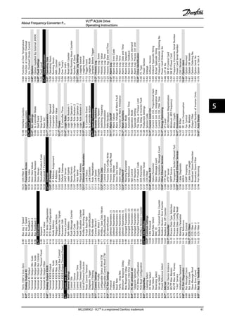
1. 3-15 Reference 1 Source
5-1*
130BB848.10
3-15 Reference Resource
[1]] Analog input 53
14.7% 0.00A 1(1)
References
Illustration 5.1 References 3-15 Reference 1 Source
2. 3-02 Minimum Reference. Set minimum internal
frequency converter reference to 0 Hz. (This sets
the minimum frequency converter speed at 0 Hz.)
Q3-21
130BT762.10
3-02 Minimum Reference
0.000 Hz
14.7% 0.00A 1(1)
Analog Reference
Illustration 5.2 Analog Reference 3-02 Minimum Reference
3. 3-03 Maximum Reference. Set maximum internal
frequency converter reference to 60 Hz. (This sets
the maximum frequency converter speed at 60
Hz. Note that 50/60 Hz is a regional variation.)
Q3-21
130BT763.113-03 Maximum Reference
50.000 Hz
14.7% 0.00A 1(1)
Analog Reference
Illustration 5.3 Analog Reference 3-03 Maximum Reference
4. 6-10 Terminal 53 Low Voltage. Set minimum
external voltage reference on Terminal 53 at 0 V.
(This sets the minimum input signal at 0 V.)
About Frequency Converter P...
VLT® AQUA Drive
Operating Instructions
34 MG20M902 - VLT® is a registered Danfoss trademark
55](https://image.slidesharecdn.com/vltaquafc202-140613202655-phpapp01/85/Vlt-aqua-fc-202-38-320.jpg)
![1. Press [Main Menu] twice, scroll to parameter
group 5-** Digital In/Out and press [OK].
130BT768.10
2-** Brakes
3-** Reference / Ramps
4-** Limits / Warnings
5-** Digital In/Out
14.6% 0.00A 1(1)
Main Menu
Illustration 5.9 6-15 Terminal 53 High Ref./Feedb. Value
2. Scroll to parameter group 5-1* Digital Inputs and
press [OK].
130BT769.10
5-0* Digital I/O mode
5-1* Digital Inputs
5-4* Relays
5-5* Pulse Input
14.7% 0.00A 1(1)
Digital In/Out 5-**
Illustration 5.10 Digital In/Out
3. Scroll to 5-10 Terminal 18 Digital Input. Press [OK]
to access function choices. The default setting
Start is shown.
5-1*
130BT770.10
5-10 Terminal 18 Digital
Input
[8]] Start
14.7% 0.00A 1(1)
Digital Inputs
Illustration 5.11 Digital Inputs
5.4 International/North American Default
Parameter Settings
Setting 0-03 Regional Settings to International or North
America changes the default settings for some parameters.
Table 5.1 lists those parameters that are effected.
Parameter International
Default Parameter
Value
North American
Default Parameter
Value
0-03 Regional
Settings
International North America
0-71 Date Format YYYY-MM-DD MM/DD/YYYY
0-72 Time Format 24h 12h
Parameter International
Default Parameter
Value
North American
Default Parameter
Value
1-20 Motor Power
[kW]
See Note 1 See Note 1
1-21 Motor Power
[HP]
See Note 2 See Note 2
1-22 Motor Voltage 230 V/400 V/575 V 208 V/460 V/575 V
1-23 Motor
Frequency
20-1000 Hz 60 Hz
3-03 Maximum
Reference
50 Hz 60 Hz
3-04 Reference
Function
Sum External/Preset
4-13 Motor Speed
High Limit [RPM]
See Note 3
1500 RPM 1800 RPM
4-14 Motor Speed
High Limit [Hz]
See Note 4
50 Hz 60 Hz
4-19 Max Output
Frequency
1.0 - 1000.0 Hz 120 Hz
4-53 Warning Speed
High
1500 RPM 1800 RPM
5-12 Terminal 27
Digital Input
Coast inverse External interlock
5-40 Function Relay Alarm No alarm
6-15 Terminal 53
High Ref./Feedb.
Value
50 60
6-50 Terminal 42
Output
100 Speed 4-20mA
14-20 Reset Mode Automatic reset x 10 Infinite auto reset
22-85 Speed at
Design Point [RPM]
See Note 3
1500 RPM 1800 RPM
22-86 Speed at
Design Point [Hz]
50 Hz 60 Hz
Table 5.1 International/North American Default Parameter Settings
Note 1: 1-20 Motor Power [kW] is only visible when 0-03 Regional
Settings is set to [0] International.
Note 2: 1-21 Motor Power [HP], is only visible when 0-03 Regional
Settings is set to [1] North America.
Note 3: This parameter is only visible when 0-02 Motor Speed Unit is
set to [0] RPM.
Note 4: This parameter is only visible when 0-02 Motor Speed Unit is
set to [1] Hz.
Changes made to default settings are stored and available
for viewing in the quick menu along with any
programming entered into parameters.
1. Press [Quick Menu].
2. Scroll to Q5 Changes Made and press [OK].
About Frequency Converter P...
VLT® AQUA Drive
Operating Instructions
36 MG20M902 - VLT® is a registered Danfoss trademark
55](https://image.slidesharecdn.com/vltaquafc202-140613202655-phpapp01/85/Vlt-aqua-fc-202-40-320.jpg)
![130BP089.10
Q1 My Personal Menu
Q2 Quick Setup
Q3 Function Setups
Q5 Changes Made
25.9% 0.00A 1(1)
Quick Menus
Illustration 5.12 Quick Menus
3. Select Q5-2 Since Factory Setting to view all
programming changes or Q5-1 Last 10 Changes
for the most recent.
Q5
130BP090.10
Q5-1 Last 10 Changes
Q5-2 Since Factory Setti...
Q5-3 Input Assignments
25.9% 0.00A 1(1)
Changes Made
Illustration 5.13 Changes Made
5.5 Parameter Menu Structure
Establishing the correct programming for applications
often requires setting functions in several related
parameters. These parameter settings provide the
frequency converter with system details it needs to
operate properly. System details may include such things
as input and output signal types, programming terminals,
minimum and maximum signal ranges, custom displays,
automatic restart, and other features.
• See the LCP display to view detailed parameter
programming and setting options
• Press [Info] in any menu location to view
additional details for that function
• Press and hold [Main Menu] to enter a parameter
number for direct access to that parameter
• Details for common application set ups are
provided in 6 Application Set Up Examples.
About Frequency Converter P...
VLT® AQUA Drive
Operating Instructions
MG20M902 - VLT® is a registered Danfoss trademark 37
5 5](https://image.slidesharecdn.com/vltaquafc202-140613202655-phpapp01/85/Vlt-aqua-fc-202-41-320.jpg)
![5.5.1 Quick Menu Structure
Q2QuickSetup0-37DisplayText120-12Reference/FeedbackUnitTrendingComparison29-13DeragSpeed[RPM]
0-01Language0-38DisplayText23-02MinimumReferenceQ7WaterandPumps29-14DeragSpeed[Hz]
0-02MotorSpeedUnit0-39DisplayText33-03MaximumReferenceQ7-1PipeFill29-15DeragOffDelay
1-20MotorPower[kW]Q3-12AnalogOutput6-20Terminal54LowVoltageQ7-10HorizontalPipes29-22DeragPowerFactor
1-22MotorVoltage6-50Terminal42Output6-21Terminal54HighVoltage29-00PipeFillEnable29-23DeragPowerDelay
1-23MotorFrequency6-51Terminal42OutputMinScale6-24Terminal54LowRef./Feedb.
Value
29-01PipeFillSpeed[RPM]29-24LowSpeed[RPM]
1-24MotorCurrent6-52Terminal42OutputMaxScale6-25Terminal54HighRef./Feedb.
Value
29-02PipeFillSpeed[Hz]29-25LowSpeed[Hz]
1-25MotorNominalSpeedQ3-13Relays
Optionrelaysifapplicable
6-00LiveZeroTimeoutTime29-03PipeFillTime29-26LowSpeedPower[kW]
3-41Ramp1RampUpTimeRelay1⇒5-40FunctionRelay6-01LiveZeroTimeoutFunction29-04PipeFillRate29-27LowSpeedPower[HP]
3-42Ramp1RampDownTimeRelay2⇒5-40FunctionRelayQ3-31PIDSettings29-05FilledSetpoint29-28HighSpeed[RPM]
4-11MotorSpeedLowLimit[RPM]Q3-2OpenLoopSettings20-81PIDNormal/InverseControl29-05FilledSetpoint29-29HighSpeed[Hz]
4-13MotorSpeedHighLimit[RPM]Q3-20DigitalReference20-82PIDStartSpeed[RPM]29-06No-FlowDisableTimer29-30HighSpeedPower[kW]
1-29AutomaticMotorAdaptation
(AMA)
3-02MinimumReference20-21Setpoint1Q7-11VerticalPipes29-31HighSpeedPower[HP]
Q3FunctionSetup3-03MaximumReference20-93PIDProportionalGain29-00PipeFillEnable29-32DeragOnRefBandwidth
Q3-1GeneralSettings3-10PresetReference20-94PIDIntegralTime29-04PipeFillRateQ7-3DryRun
Q3-10ClockSettings5-13Terminal29DigitalInputQ5ChangesMade29-05FilledSetpoint22-21LowPowerDetection
0-70DateandTime5-14Terminal32DigitalInputQ5-1Last10Changes29-06No-FlowDisableTimer22-20LowPowerAutoSet-up
0-71DateFormat5-15Terminal33DigitalInputQ5-2SinceFactorySettingQ7-12MixedSystems22-27DryPumpDelay
0-72TimeFormatQ3-21AnalogReferenceQ5-3InputAssignments29-00PipeFillEnable22-26DryPumpFunction
0-74DST/Summertime3-02MinimumReferenceQ6Loggings29-01PipeFillSpeed[RPM]Q7-4EndofCurveDetection
0-76DST/SummertimeStart3-03MaximumReferenceReference[Unit]29-02PipeFillSpeed[Hz]22-50EndofCurveFunction
0-77DST_SummertimeEnd6-10Terminal53LowVoltageAnalogInput5329-03PipeFillTime22-51EndofCurveDelay
Q3-11DisplaySettings6-11Terminal53HighVoltageMotorcurrent29-05FilledSetpointQ7-5SleepMode
0-20DisplayLine1.1Small6-14Terminal53LowRef./Feedb.
Value
Frequency29-06No-FlowDisableTimerQ7-50LowSpeed
0-21DisplayLine1.2Small6-15Terminal53HighRef./Feedb.
Value
Feedback[Unit]Q7-2Deragging22-22LowSpeedDetection
0-22DisplayLine1.3SmallQ3-3ClosedLoopSettingsEnergyLog29-10DeragCycles22-23No-FlowFunction
0-23DisplayLine2LargeQ3-30FeedbackSettingsTrendingContBin29-11DeragatStart/Stop22-24No-FlowDelay
0-24DisplayLine3Large1-00ConfigurationModeTrendingTimedBin29-12DeraggingRunTime22-28No-FlowLowSpeed[RPM]
Table5.2QuickMenuStructure
About Frequency Converter P...
VLT® AQUA Drive
Operating Instructions
38 MG20M902 - VLT® is a registered Danfoss trademark
55](https://image.slidesharecdn.com/vltaquafc202-140613202655-phpapp01/85/Vlt-aqua-fc-202-42-320.jpg)
![22-29No-FlowLowSpeed[Hz]22-24No-FlowDelay22-20LowPowerAutoSet-upQ7-6FlowCompensation22-90FlowatRatedSpeed
22-40MinimumRunTime22-20LowPowerAutoSet-up22-22LowSpeedDetection22-80FlowCompensationQ7-7SpecialRamps
22-41MinimumSleepTime22-40MinimumRunTime22-28No-FlowLowSpeed[RPM]22-81Square-linearCurveApproxi-
mation
3-84InitialRampTime
22-42Wake-upSpeed[RPM]22-41MinimumSleepTime22-29No-FlowLowSpeed[Hz]22-82WorkPointCalculation3-88FinalRampTime
22-43Wake-upSpeed[Hz]22-42Wake-upSpeed[RPM]22-40MinimumRunTime22-83SpeedatNo-Flow[RPM]3-85CheckValveRampTime
22-44Wake-upRef./FBDifference22-43Wake-upSpeed[Hz]22-41MinimumSleepTime22-84SpeedatNo-Flow[Hz]3-86CheckValveRampEndSpeed
[RPM]
22-45SetpointBoost22-44Wake-upRef./FBDifference22-42Wake-upSpeed[RPM]22-85SpeedatDesignPoint[RPM]3-87CheckValveRampEndSpeed
[HZ]
22-46MaximumBoostTime22-45SetpointBoost22-43Wake-upSpeed[Hz]22-86SpeedatDesignPoint[Hz]
Q7-51LowPower22-46MaximumBoostTime22-44Wake-upRef./FBDifference22-87PressureatNo-FlowSpeed
22-21LowPowerDetectionQ7-52LowSpeed/Power22-45SetpointBoost22-88PressureatRatedSpeed
22-23No-FlowFunction22-21LowPowerDetection22-46MaximumBoostTime22-89FlowatDesignPoint
Table5.3
About Frequency Converter P...
VLT® AQUA Drive
Operating Instructions
MG20M902 - VLT® is a registered Danfoss trademark 39
5 5](https://image.slidesharecdn.com/vltaquafc202-140613202655-phpapp01/85/Vlt-aqua-fc-202-43-320.jpg)
![5.5.2MainMenu
Structure
0-**Operation/Display
0-0*BasicSettings
0-01Language
0-02MotorSpeedUnit
0-03RegionalSettings
0-04OperatingStateatPower-up
0-05LocalModeUnit
0-1*Set-upOperations
0-10ActiveSet-up
0-11ProgrammingSet-up
0-12ThisSet-upLinkedto
0-13Readout:LinkedSet-ups
0-14Readout:Prog.Set-ups/Channel
0-2*LCPDisplay
0-20DisplayLine1.1Small
0-21DisplayLine1.2Small
0-22DisplayLine1.3Small
0-23DisplayLine2Large
0-24DisplayLine3Large
0-25MyPersonalMenu
0-3*LCPCustomReadout
0-30CustomReadoutUnit
0-31CustomReadoutMinValue
0-32CustomReadoutMaxValue
0-37DisplayText1
0-38DisplayText2
0-39DisplayText3
0-4*LCPKeypad
0-40[Handon]KeyonLCP
0-41[Off]KeyonLCP
0-42[Autoon]KeyonLCP
0-43[Reset]KeyonLCP
0-44[Off/Reset]KeyonLCP
0-45[DriveBypass]KeyonLCP
0-5*Copy/Save
0-50LCPCopy
0-51Set-upCopy
0-6*Password
0-60MainMenuPassword
0-61AccesstoMainMenuw/oPassword
0-65PersonalMenuPassword
0-66AccesstoPersonalMenuw/o
Password
0-67BusPasswordAccess
0-7*ClockSettings
0-70DateandTime
0-71DateFormat
0-72TimeFormat
0-74DST/Summertime
0-76DST/SummertimeStart
0-77DST/SummertimeEnd
0-79ClockFault
0-81WorkingDays
0-82AdditionalWorkingDays
0-83AdditionalNon-WorkingDays
0-89DateandTimeReadout
1-**LoadandMotor
1-0*GeneralSettings
1-00ConfigurationMode
1-01MotorControlPrinciple
1-03TorqueCharacteristics
1-06ClockwiseDirection
1-1*MotorSelection
1-10MotorConstruction
1-1*VVC+PM
1-14DampingGain
1-15LowSpeedFilterTimeConst.
1-16HighSpeedFilterTimeConst.
1-17Voltagefiltertimeconst.
1-2*MotorData
1-20MotorPower[kW]
1-21MotorPower[HP]
1-22MotorVoltage
1-23MotorFrequency
1-24MotorCurrent
1-25MotorNominalSpeed
1-26MotorCont.RatedTorque
1-28MotorRotationCheck
1-29AutomaticMotorAdaptation(AMA)
1-3*Adv.MotorData
1-30StatorResistance(Rs)
1-31RotorResistance(Rr)
1-33StatorLeakageReactance(X1)
1-34RotorLeakageReactance(X2)
1-35MainReactance(Xh)
1-36IronLossResistance(Rfe)
1-37d-axisInductance(Ld)
1-39MotorPoles
1-40BackEMFat1000RPM
1-46PositionDetectionGain
1-5*LoadIndep.Setting
1-50MotorMagnetisationatZeroSpeed
1-51MinSpeedNormalMagnetising[RPM]
1-52MinSpeedNormalMagnetising[Hz]
1-55V/fCharacteristic-V
1-56V/fCharacteristic-f
1-58FlystartTestPulsesCurrent
1-59FlystartTestPulsesFrequency
1-6*LoadDepen.Setting
1-60LowSpeedLoadCompensation
1-61HighSpeedLoadCompensation
1-62SlipCompensation
1-63SlipCompensationTimeConstant
1-64ResonanceDampening
1-65ResonanceDampeningTimeConstant
1-66Min.CurrentatLowSpeed
1-7*StartAdjustments
1-70PMStartMode
1-71StartDelay
1-72StartFunction
1-73FlyingStart
1-74StartSpeed[RPM]
1-75StartSpeed[Hz]
1-76StartCurrent
1-8*StopAdjustments
1-80FunctionatStop
1-81MinSpeedforFunctionatStop[RPM]
1-82MinSpeedforFunctionatStop[Hz]
1-86TripSpeedLow[RPM]
1-87TripSpeedLow[Hz]
1-9*MotorTemperature
1-90MotorThermalProtection
1-91MotorExternalFan
1-93ThermistorSource
2-**Brakes
2-0*DC-Brake
2-00DCHold/PreheatCurrent
2-01DCBrakeCurrent
2-02DCBrakingTime
2-03DCBrakeCutInSpeed[RPM]
2-04DCBrakeCutInSpeed[Hz]
2-06ParkingCurrent
2-07ParkingTime
2-1*BrakeEnergyFunct.
2-10BrakeFunction
2-11BrakeResistor(ohm)
2-12BrakePowerLimit(kW)
2-13BrakePowerMonitoring
2-15BrakeCheck
2-16ACbrakeMax.Current
2-17Over-voltageControl
3-**Reference/Ramps
3-0*ReferenceLimits
3-02MinimumReference
3-03MaximumReference
3-04ReferenceFunction
3-1*References
3-10PresetReference
3-11JogSpeed[Hz]
3-13ReferenceSite
3-14PresetRelativeReference
3-15Reference1Source
3-16Reference2Source
3-17Reference3Source
3-19JogSpeed[RPM]
3-4*Ramp1
3-41Ramp1RampUpTime
3-42Ramp1RampDownTime
3-5*Ramp2
3-51Ramp2RampUpTime
3-52Ramp2RampDownTime
3-8*OtherRamps
3-80JogRampTime
3-81QuickStopRampTime
3-84InitialRampTime
3-85CheckValveRampTime
3-86CheckValveRampEndSpeed[RPM]
3-87CheckValveRampEndSpeed[HZ]
3-88FinalRampTime
3-9*DigitalPot.Meter
3-90StepSize
3-91RampTime
3-92PowerRestore
3-93MaximumLimit
3-94MinimumLimit
3-95RampDelay
4-**Limits/Warnings
4-1*MotorLimits
4-10MotorSpeedDirection
4-11MotorSpeedLowLimit[RPM]
4-12MotorSpeedLowLimit[Hz]
4-13MotorSpeedHighLimit[RPM]
4-14MotorSpeedHighLimit[Hz]
4-16TorqueLimitMotorMode
4-17TorqueLimitGeneratorMode
4-18CurrentLimit
4-19MaxOutputFrequency
4-5*Adj.Warnings
4-50WarningCurrentLow
4-51WarningCurrentHigh
4-52WarningSpeedLow
4-53WarningSpeedHigh
4-54WarningReferenceLow
4-55WarningReferenceHigh
4-56WarningFeedbackLow
4-57WarningFeedbackHigh
4-58MissingMotorPhaseFunction
4-6*SpeedBypass
4-60BypassSpeedFrom[RPM]
4-61BypassSpeedFrom[Hz]
4-62BypassSpeedTo[RPM]
4-63BypassSpeedTo[Hz]
4-64Semi-AutoBypassSet-up
5-**DigitalIn/Out
5-0*DigitalI/Omode
5-00DigitalI/OMode
5-01Terminal27Mode
5-02Terminal29Mode
5-1*DigitalInputs
5-10Terminal18DigitalInput
5-11Terminal19DigitalInput
5-12Terminal27DigitalInput
5-13Terminal29DigitalInput
5-14Terminal32DigitalInput
5-15Terminal33DigitalInput
5-16TerminalX30/2DigitalInput
5-17TerminalX30/3DigitalInput
5-18TerminalX30/4DigitalInput
5-19Terminal37DigitalInput
5-3*DigitalOutputs
5-30Terminal27DigitalOutput
5-31Terminal29DigitalOutput
5-32TermX30/6DigiOut(MCB101)
5-33TermX30/7DigiOut(MCB101)
5-4*Relays
5-40FunctionRelay
5-41OnDelay,Relay
5-42OffDelay,Relay
5-5*PulseInput
5-50Term.29LowFrequency
5-51Term.29HighFrequency
5-52Term.29LowRef./Feedb.Value
5-53Term.29HighRef./Feedb.Value
5-54PulseFilterTimeConstant#29
5-55Term.33LowFrequency
5-56Term.33HighFrequency
5-57Term.33LowRef./Feedb.Value
5-58Term.33HighRef./Feedb.Value
5-59PulseFilterTimeConstant#33
5-6*PulseOutput
5-60Terminal27PulseOutputVariable
5-62PulseOutputMaxFreq#27
5-63Terminal29PulseOutputVariable
5-65PulseOutputMaxFreq#29
5-66TerminalX30/6PulseOutputVariable
5-68PulseOutputMaxFreq#X30/6
5-8*I/OOptions
5-80AHFCapReconnectDelay
5-9*BusControlled
5-90Digital&RelayBusControl
5-93PulseOut#27BusControl
5-94PulseOut#27TimeoutPreset
5-95PulseOut#29BusControl
5-96PulseOut#29TimeoutPreset
5-97PulseOut#X30/6BusControl
5-98PulseOut#X30/6TimeoutPreset
6-**AnalogIn/Out
6-0*AnalogI/OMode
6-00LiveZeroTimeoutTime
6-01LiveZeroTimeoutFunction
6-1*AnalogInput53
6-10Terminal53LowVoltage
6-11Terminal53HighVoltage
6-12Terminal53LowCurrent
6-13Terminal53HighCurrent
6-14Terminal53LowRef./Feedb.Value
6-15Terminal53HighRef./Feedb.Value
6-16Terminal53FilterTimeConstant
6-17Terminal53LiveZero
6-2*AnalogInput54
6-20Terminal54LowVoltage
6-21Terminal54HighVoltage
6-22Terminal54LowCurrent
6-23Terminal54HighCurrent
6-24Terminal54LowRef./Feedb.Value
6-25Terminal54HighRef./Feedb.Value
6-26Terminal54FilterTimeConstant
6-27Terminal54LiveZero
6-3*AnalogInputX30/11
6-30TerminalX30/11LowVoltage
6-31TerminalX30/11HighVoltage
6-34Term.X30/11LowRef./Feedb.Value
6-35Term.X30/11HighRef./Feedb.Value
6-36Term.X30/11FilterTimeConstant
6-37Term.X30/11LiveZero
6-4*AnalogInputX30/12
6-40TerminalX30/12LowVoltage
6-41TerminalX30/12HighVoltage
6-44Term.X30/12LowRef./Feedb.Value
6-45Term.X30/12HighRef./Feedb.Value
6-46Term.X30/12FilterTimeConstant
About Frequency Converter P...
VLT® AQUA Drive
Operating Instructions
40 MG20M902 - VLT® is a registered Danfoss trademark
55](https://image.slidesharecdn.com/vltaquafc202-140613202655-phpapp01/85/Vlt-aqua-fc-202-44-320.jpg)
![15-71SlotAOptionSWVersion
15-72OptioninSlotB
15-73SlotBOptionSWVersion
15-74OptioninSlotC0/E0
15-75SlotC0/E0OptionSWVersion
15-76OptioninSlotC1/E1
15-77SlotC1/E1OptionSWVersion
15-9*ParameterInfo
15-92DefinedParameters
15-93ModifiedParameters
15-98DriveIdentification
15-99ParameterMetadata
16-**DataReadouts
16-0*GeneralStatus
16-00ControlWord
16-01Reference[Unit]
16-02Reference[%]
16-03StatusWord
16-05MainActualValue[%]
16-09CustomReadout
16-1*MotorStatus
16-10Power[kW]
16-11Power[hp]
16-12MotorVoltage
16-13Frequency
16-14Motorcurrent
16-15Frequency[%]
16-16Torque[Nm]
16-17Speed[RPM]
16-18MotorThermal
16-20MotorAngle
16-22Torque[%]
16-3*DriveStatus
16-30DCLinkVoltage
16-32BrakeEnergy/s
16-33BrakeEnergy/2min
16-34HeatsinkTemp.
16-35InverterThermal
16-36Inv.Nom.Current
16-37Inv.Max.Current
16-38SLControllerState
16-39ControlCardTemp.
16-40LoggingBufferFull
16-49CurrentFaultSource
16-5*Ref.&Feedb.
16-50ExternalReference
16-52Feedback[Unit]
16-53DigiPotReference
16-54Feedback1[Unit]
16-55Feedback2[Unit]
16-56Feedback3[Unit]
16-58PIDOutput[%]
16-59AdjustedSetpoint
16-6*Inputs&Outputs
16-60DigitalInput
16-61Terminal53SwitchSetting
16-62AnalogInput53
16-63Terminal54SwitchSetting
16-64AnalogInput54
16-65AnalogOutput42[mA]
16-66DigitalOutput[bin]
16-67PulseInput#29[Hz]
16-68PulseInput#33[Hz]
16-69PulseOutput#27[Hz]
16-70PulseOutput#29[Hz]
16-71RelayOutput[bin]
16-72CounterA
16-73CounterB
16-75AnalogInX30/11
16-76AnalogInX30/12
16-77AnalogOutX30/8[mA]
16-8*Fieldbus&FCPort
16-80FieldbusCTW1
16-82FieldbusREF1
16-84Comm.OptionSTW
16-85FCPortCTW1
16-86FCPortREF1
16-9*DiagnosisReadouts
16-90AlarmWord
16-91AlarmWord2
16-92WarningWord
16-93WarningWord2
16-94Ext.StatusWord
16-95Ext.StatusWord2
16-96MaintenanceWord
18-**Info&Readouts
18-0*MaintenanceLog
18-00MaintenanceLog:Item
18-01MaintenanceLog:Action
18-02MaintenanceLog:Time
18-03MaintenanceLog:DateandTime
18-3*AnalogReadouts
18-30AnalogInputX42/1
18-31AnalogInputX42/3
18-32AnalogInputX42/5
18-33AnalogOutX42/7[V]
18-34AnalogOutX42/9[V]
18-35AnalogOutX42/11[V]
18-36AnalogInputX48/2[mA]
18-37Temp.InputX48/4
18-38Temp.InputX48/7
18-39Temp.InputX48/10
18-6*Inputs&Outputs2
18-60DigitalInput2
20-**DriveClosedLoop
20-0*Feedback
20-00Feedback1Source
20-01Feedback1Conversion
20-02Feedback1SourceUnit
20-03Feedback2Source
20-04Feedback2Conversion
20-05Feedback2SourceUnit
20-06Feedback3Source
20-07Feedback3Conversion
20-08Feedback3SourceUnit
20-12Reference/FeedbackUnit
20-2*Feedback/Setpoint
20-20FeedbackFunction
20-21Setpoint1
20-22Setpoint2
20-23Setpoint3
20-7*PIDAutotuning
20-70ClosedLoopType
20-71PIDPerformance
20-72PIDOutputChange
20-73MinimumFeedbackLevel
20-74MaximumFeedbackLevel
20-79PIDAutotuning
20-8*PIDBasicSettings
20-81PIDNormal/InverseControl
20-82PIDStartSpeed[RPM]
20-83PIDStartSpeed[Hz]
20-84OnReferenceBandwidth
20-9*PIDController
20-91PIDAntiWindup
20-93PIDProportionalGain
20-94PIDIntegralTime
20-95PIDDifferentiationTime
20-96PIDDiff.GainLimit
21-**Ext.ClosedLoop
21-0*Ext.CLAutotuning
21-00ClosedLoopType
21-01PIDPerformance
21-02PIDOutputChange
21-03MinimumFeedbackLevel
21-04MaximumFeedbackLevel
21-09PIDAutoTuning
21-1*Ext.CL1Ref./Fb.
21-10Ext.1Ref./FeedbackUnit
21-11Ext.1MinimumReference
21-12Ext.1MaximumReference
21-13Ext.1ReferenceSource
21-14Ext.1FeedbackSource
21-15Ext.1Setpoint
21-17Ext.1Reference[Unit]
21-18Ext.1Feedback[Unit]
21-19Ext.1Output[%]
21-2*Ext.CL1PID
21-20Ext.1Normal/InverseControl
21-21Ext.1ProportionalGain
21-22Ext.1IntegralTime
21-23Ext.1DifferentationTime
21-24Ext.1Dif.GainLimit
21-3*Ext.CL2Ref./Fb.
21-30Ext.2Ref./FeedbackUnit
21-31Ext.2MinimumReference
21-32Ext.2MaximumReference
21-33Ext.2ReferenceSource
21-34Ext.2FeedbackSource
21-35Ext.2Setpoint
21-37Ext.2Reference[Unit]
21-38Ext.2Feedback[Unit]
21-39Ext.2Output[%]
21-4*Ext.CL2PID
21-40Ext.2Normal/InverseControl
21-41Ext.2ProportionalGain
21-42Ext.2IntegralTime
21-43Ext.2DifferentationTime
21-44Ext.2Dif.GainLimit
21-5*Ext.CL3Ref./Fb.
21-50Ext.3Ref./FeedbackUnit
21-51Ext.3MinimumReference
21-52Ext.3MaximumReference
21-53Ext.3ReferenceSource
21-54Ext.3FeedbackSource
21-55Ext.3Setpoint
21-57Ext.3Reference[Unit]
21-58Ext.3Feedback[Unit]
21-59Ext.3Output[%]
21-6*Ext.CL3PID
21-60Ext.3Normal/InverseControl
21-61Ext.3ProportionalGain
21-62Ext.3IntegralTime
21-63Ext.3DifferentationTime
21-64Ext.3Dif.GainLimit
22-**Appl.Functions
22-0*Miscellaneous
22-00ExternalInterlockDelay
22-2*No-FlowDetection
22-20LowPowerAutoSet-up
22-21LowPowerDetection
22-22LowSpeedDetection
22-23No-FlowFunction
22-24No-FlowDelay
22-26DryPumpFunction
22-27DryPumpDelay
22-28No-FlowLowSpeed[RPM]
22-29No-FlowLowSpeed[Hz]
22-3*No-FlowPowerTuning
22-30No-FlowPower
22-31PowerCorrectionFactor
22-32LowSpeed[RPM]
22-33LowSpeed[Hz]
22-34LowSpeedPower[kW]
22-35LowSpeedPower[HP]
22-36HighSpeed[RPM]
22-37HighSpeed[Hz]
22-38HighSpeedPower[kW]
22-39HighSpeedPower[HP]
22-4*SleepMode
22-40MinimumRunTime
22-41MinimumSleepTime
22-42Wake-upSpeed[RPM]
22-43Wake-upSpeed[Hz]
22-44Wake-upRef./FBDifference
22-45SetpointBoost
22-46MaximumBoostTime
22-5*EndofCurve
22-50EndofCurveFunction
22-51EndofCurveDelay
22-6*BrokenBeltDetection
22-60BrokenBeltFunction
22-61BrokenBeltTorque
22-62BrokenBeltDelay
22-7*ShortCycleProtection
22-75ShortCycleProtection
22-76IntervalbetweenStarts
22-77MinimumRunTime
22-78MinimumRunTimeOverride
22-79MinimumRunTimeOverrideValue
22-8*FlowCompensation
22-80FlowCompensation
22-81Square-linearCurveApproximation
22-82WorkPointCalculation
22-83SpeedatNo-Flow[RPM]
22-84SpeedatNo-Flow[Hz]
22-85SpeedatDesignPoint[RPM]
22-86SpeedatDesignPoint[Hz]
22-87PressureatNo-FlowSpeed
22-88PressureatRatedSpeed
22-89FlowatDesignPoint
22-90FlowatRatedSpeed
23-**Time-basedFunctions
23-0*TimedActions
23-00ONTime
23-01ONAction
23-02OFFTime
23-03OFFAction
23-04Occurrence
23-1*Maintenance
23-10MaintenanceItem
23-11MaintenanceAction
23-12MaintenanceTimeBase
23-13MaintenanceTimeInterval
23-14MaintenanceDateandTime
23-1*MaintenanceReset
23-15ResetMaintenanceWord
23-16MaintenanceText
23-5*EnergyLog
23-50EnergyLogResolution
23-51PeriodStart
23-53EnergyLog
23-54ResetEnergyLog
23-6*Trending
23-60TrendVariable
23-61ContinuousBinData
23-62TimedBinData
23-63TimedPeriodStart
23-64TimedPeriodStop
23-65MinimumBinValue
23-66ResetContinuousBinData
23-67ResetTimedBinData
23-8*PaybackCounter
23-80PowerReferenceFactor
23-81EnergyCost
23-82Investment
23-83EnergySavings
23-84CostSavings
24-**Appl.Functions2
24-1*DriveBypass
24-10DriveBypassFunction
24-11DriveBypassDelayTime
25-**CascadeController
25-0*SystemSettings
25-00CascadeController
About Frequency Converter P...
VLT® AQUA Drive
Operating Instructions
42 MG20M902 - VLT® is a registered Danfoss trademark
55](https://image.slidesharecdn.com/vltaquafc202-140613202655-phpapp01/85/Vlt-aqua-fc-202-46-320.jpg)
![25-02MotorStart
25-04PumpCycling
25-05FixedLeadPump
25-06NumberofPumps
25-2*BandwidthSettings
25-20StagingBandwidth
25-21OverrideBandwidth
25-22FixedSpeedBandwidth
25-23SBWStagingDelay
25-24SBWDestagingDelay
25-25OBWTime
25-26DestageAtNo-Flow
25-27StageFunction
25-28StageFunctionTime
25-29DestageFunction
25-30DestageFunctionTime
25-4*StagingSettings
25-40RampDownDelay
25-41RampUpDelay
25-42StagingThreshold
25-43DestagingThreshold
25-44StagingSpeed[RPM]
25-45StagingSpeed[Hz]
25-46DestagingSpeed[RPM]
25-47DestagingSpeed[Hz]
25-5*AlternationSettings
25-50LeadPumpAlternation
25-51AlternationEvent
25-52AlternationTimeInterval
25-53AlternationTimerValue
25-54AlternationPredefinedTime
25-55AlternateifLoad<50%
25-56StagingModeatAlternation
25-58RunNextPumpDelay
25-59RunonMainsDelay
25-8*Status
25-80CascadeStatus
25-81PumpStatus
25-82LeadPump
25-83RelayStatus
25-84PumpONTime
25-85RelayONTime
25-86ResetRelayCounters
25-9*Service
25-90PumpInterlock
25-91ManualAlternation
26-**AnalogI/OOption
26-0*AnalogI/OMode
26-00TerminalX42/1Mode
26-01TerminalX42/3Mode
26-02TerminalX42/5Mode
26-1*AnalogInputX42/1
26-10TerminalX42/1LowVoltage
26-11TerminalX42/1HighVoltage
26-14Term.X42/1LowRef./Feedb.Value
26-15Term.X42/1HighRef./Feedb.Value
26-16Term.X42/1FilterTimeConstant
26-17Term.X42/1LiveZero
26-2*AnalogInputX42/3
26-20TerminalX42/3LowVoltage
26-21TerminalX42/3HighVoltage
26-24Term.X42/3LowRef./Feedb.Value
26-25Term.X42/3HighRef./Feedb.Value
26-26Term.X42/3FilterTimeConstant
26-27Term.X42/3LiveZero
26-3*AnalogInputX42/5
26-30TerminalX42/5LowVoltage
26-31TerminalX42/5HighVoltage
26-34Term.X42/5LowRef./Feedb.Value
26-35Term.X42/5HighRef./Feedb.Value
26-36Term.X42/5FilterTimeConstant
26-37Term.X42/5LiveZero
26-4*AnalogOutX42/7
26-40TerminalX42/7Output
26-41TerminalX42/7Min.Scale
26-42TerminalX42/7Max.Scale
26-43TerminalX42/7BusControl
26-44TerminalX42/7TimeoutPreset
26-5*AnalogOutX42/9
26-50TerminalX42/9Output
26-51TerminalX42/9Min.Scale
26-52TerminalX42/9Max.Scale
26-53TerminalX42/9BusControl
26-54TerminalX42/9TimeoutPreset
26-6*AnalogOutX42/11
26-60TerminalX42/11Output
26-61TerminalX42/11Min.Scale
26-62TerminalX42/11Max.Scale
26-63TerminalX42/11BusControl
26-64TerminalX42/11TimeoutPreset
27-**CascadeCTLOption
27-0*Control&Status
27-01PumpStatus
27-02ManualPumpControl
27-03CurrentRuntimeHours
27-04PumpTotalLifetimeHours
27-1*Configuration
27-10CascadeController
27-11NumberOfDrives
27-12NumberOfPumps
27-14PumpCapacity
27-16RuntimeBalancing
27-17MotorStarters
27-18SpinTimeforUnusedPumps
27-19ResetCurrentRuntimeHours
27-2*BandwidthSettings
27-20NormalOperatingRange
27-21OverrideLimit
27-22FixedSpeedOnlyOperatingRange
27-23StagingDelay
27-24DestagingDelay
27-25OverrideHoldTime
27-27MinSpeedDestageDelay
27-3*StagingSpeed
27-30AutoTuneStagingSpeeds
27-31StageOnSpeed[RPM]
27-32StageOnSpeed[Hz]
27-33StageOffSpeed[RPM]
27-34StageOffSpeed[Hz]
27-4*StagingSettings
27-40AutoTuneStagingSettings
27-41RampDownDelay
27-42RampUpDelay
27-43StagingThreshold
27-44DestagingThreshold
27-45StagingSpeed[RPM]
27-46StagingSpeed[Hz]
27-47DestagingSpeed[RPM]
27-48DestagingSpeed[Hz]
27-5*AlternateSettings
27-50AutomaticAlternation
27-51AlternationEvent
27-52AlternationTimeInterval
27-53AlternationTimerValue
27-54AlternationAtTimeofDay
27-55AlternationPredefinedTime
27-56AlternateCapacityis<
27-58RunNextPumpDelay
27-6*DigitalInputs
27-60TerminalX66/1DigitalInput
27-61TerminalX66/3DigitalInput
27-62TerminalX66/5DigitalInput
27-63TerminalX66/7DigitalInput
27-64TerminalX66/9DigitalInput
27-65TerminalX66/11DigitalInput
27-66TerminalX66/13DigitalInput
27-7*Connections
27-70Relay
27-9*Readouts
27-91CascadeReference
27-92%OfTotalCapacity
27-93CascadeOptionStatus
27-94CascadeSystemStatus
27-95AdvancedCascadeRelayOutput[bin]
27-96ExtendedCascadeRelayOutput[bin]
29-**WaterApplicationFunctions
29-0*PipeFill
29-00PipeFillEnable
29-01PipeFillSpeed[RPM]
29-02PipeFillSpeed[Hz]
29-03PipeFillTime
29-04PipeFillRate
29-05FilledSetpoint
29-06No-FlowDisableTimer
29-1*DeraggingFunction
29-10DeragCycles
29-11DeragatStart/Stop
29-12DeraggingRunTime
29-13DeragSpeed[RPM]
29-14DeragSpeed[Hz]
29-15DeragOffDelay
29-2*DeragPowerTuning
29-20DeragPower[kW]
29-21DeragPower[HP]
29-22DeragPowerFactor
29-23DeragPowerDelay
29-24LowSpeed[RPM]
29-25LowSpeed[Hz]
29-26LowSpeedPower[kW]
29-27LowSpeedPower[HP]
29-28HighSpeed[RPM]
29-29HighSpeed[Hz]
29-30HighSpeedPower[kW]
29-31HighSpeedPower[HP]
29-32DeragOnRefBandwidth
29-33PowerDeragLimit
29-34ConsecutiveDeragInterval
30-**SpecialFeatures
30-8*Compatibility(I)
30-81BrakeResistor(ohm)
31-**BypassOption
31-00BypassMode
31-01BypassStartTimeDelay
31-02BypassTripTimeDelay
31-03TestModeActivation
31-10BypassStatusWord
31-11BypassRunningHours
31-19RemoteBypassActivation
35-**SensorInputOption
35-0*Temp.InputMode
35-00Term.X48/4TemperatureUnit
35-01Term.X48/4InputType
35-02Term.X48/7TemperatureUnit
35-03Term.X48/7InputType
35-04Term.X48/10TemperatureUnit
35-05Term.X48/10InputType
35-06TemperatureSensorAlarmFunction
35-1*Temp.InputX48/4
35-14Term.X48/4FilterTimeConstant
35-15Term.X48/4Temp.Monitor
35-16Term.X48/4LowTemp.Limit
35-17Term.X48/4HighTemp.Limit
35-2*Temp.InputX48/7
35-24Term.X48/7FilterTimeConstant
35-25Term.X48/7Temp.Monitor
35-26Term.X48/7LowTemp.Limit
35-27Term.X48/7HighTemp.Limit
35-3*Temp.InputX48/10
35-34Term.X48/10FilterTimeConstant
35-35Term.X48/10Temp.Monitor
35-36Term.X48/10LowTemp.Limit
35-37Term.X48/10HighTemp.Limit
35-4*AnalogInputX48/2
35-42Term.X48/2LowCurrent
35-43Term.X48/2HighCurrent
35-44Term.X48/2LowRef./Feedb.Value
35-45Term.X48/2HighRef./Feedb.Value
35-46Term.X48/2FilterTimeConstant
35-47Term.X48/2LiveZero
About Frequency Converter P...
VLT® AQUA Drive
Operating Instructions
MG20M902 - VLT® is a registered Danfoss trademark 43
5 5](https://image.slidesharecdn.com/vltaquafc202-140613202655-phpapp01/85/Vlt-aqua-fc-202-47-320.jpg)
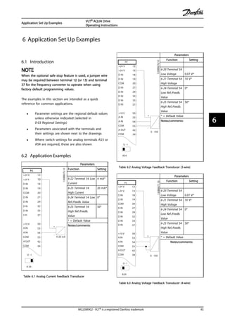
![Parameters
FC
+24 V
+24 V
D IN
D IN
D IN
COM
D IN
D IN
D IN
D IN
+10 V
A IN
A IN
COM
A OUT
COM
12
13
18
19
20
27
29
32
33
37
50
53
54
55
42
39
A53
U - I
0 - 10V
+
-
130BB678.10
Function Setting
6-10 Terminal 53
Low Voltage 0.07 V*
6-11 Terminal 53
High Voltage
10 V*
6-14 Terminal 53
Low Ref./Feedb.
Value
0*
6-15 Terminal 53
High Ref./Feedb.
Value
50*
* = Default Value
Notes/comments:
Table 6.4 Analog Speed Reference (Voltage)
NOTE
Note switch setting for selecting voltage or current.
Parameters
FC
+24 V
+24 V
D IN
D IN
D IN
COM
D IN
D IN
D IN
D IN
+10 V
A IN
A IN
COM
A OUT
COM
12
13
18
19
20
27
29
32
33
37
50
53
54
55
42
39
A53
U - I
4 - 20mA
+
-
130BB679.10
Function Setting
6-12 Terminal 53
Low Current
4 mA*
6-13 Terminal 53
High Current
20 mA*
6-14 Terminal 53
Low Ref./Feedb.
Value
0*
6-15 Terminal 53
High Ref./Feedb.
Value
50*
* = Default Value
Notes/comments:
Table 6.5 Analog Speed Reference (Current)
NOTE
Note switch setting for selecting voltage or current.
Parameters
FC
+24 V
+24 V
D IN
D IN
D IN
COM
D IN
D IN
D IN
D IN
+10 V
A IN
A IN
COM
A OUT
COM
12
13
18
19
20
27
29
32
33
37
50
53
54
55
42
39
130BB680.10
Function Setting
5-10 Terminal 18
Digital Input
[8] Start*
5-12 Terminal 27
Digital Input
[7] External
Interlock
* = Default Value
Notes/comments:
Table 6.6 Run/Stop Command with External Interlock
Parameters
FC
+24 V
+24 V
D IN
D IN
D IN
COM
D IN
D IN
D IN
D IN
+10 V
A IN
A IN
COM
A OUT
COM
R1R2
12
13
18
19
20
27
29
32
33
37
50
53
54
55
42
39
01
02
03
04
05
06
130BB681.10
Function Setting
5-10 Terminal 18
Digital Input
[8] Start*
5-12 Terminal 27
Digital Input
[7] External
Interlock
* = Default Value
Notes/comments:
If 5-12 Terminal 27 Digital Input
is set to [0] No operation, a
jumper wire to terminal 27 is
not needed.
Table 6.7 Run/Stop Command without External Interlock
Application Set Up Examples
VLT® AQUA Drive
Operating Instructions
46 MG20M902 - VLT® is a registered Danfoss trademark
66](https://image.slidesharecdn.com/vltaquafc202-140613202655-phpapp01/85/Vlt-aqua-fc-202-50-320.jpg)
![Parameters
FC
+24 V
+24 V
D IN
D IN
D IN
COM
D IN
D IN
D IN
D IN
+10 V
A IN
A IN
COM
A OUT
COM
12
13
18
19
20
27
29
32
33
37
50
53
54
55
42
39
130BB682.10
Function Setting
5-11 Terminal 19
Digital Input
[1] Reset
* = Default Value
Notes/comments:
Table 6.8 External Alarm Reset
Parameters
FC
+24 V
+24 V
D IN
D IN
D IN
COM
D IN
D IN
D IN
D IN
+10 V
A IN
A IN
COM
A OUT
COM
12
13
18
19
20
27
29
32
33
37
50
53
54
55
42
39
A53
U - I
≈5kΩ
130BB683.10
Function Setting
6-10 Terminal 53
Low Voltage 0.07 V*
6-11 Terminal 53
High Voltage
10 V*
6-14 Terminal 53
Low Ref./Feedb.
Value
0*
6-15 Terminal 53
High Ref./Feedb.
Value
50*
* = Default Value
Notes/comments:
Table 6.9 Speed Reference (using a manual potentiometer)
Parameters
FC
+24 V
+24 V
D IN
D IN
D IN
COM
D IN
D IN
D IN
D IN
+10 V
A IN
A IN
COM
A OUT
COM
R1R2
12
13
18
19
20
27
29
32
33
37
50
53
54
55
42
39
01
02
03
04
05
06
130BB684.10
Function Setting
5-10 Terminal 18
Digital Input [8] Start*
5-11 Terminal 19
Digital Input
[52] Run
Permissive
5-12 Terminal 27
Digital Input
[7] External
Interlock
5-40 Function
Relay
[167] Start
command
act.
* = Default Value
Notes/comments:
Table 6.10 Run Permissive
Application Set Up Examples
VLT® AQUA Drive
Operating Instructions
MG20M902 - VLT® is a registered Danfoss trademark 47
6 6](https://image.slidesharecdn.com/vltaquafc202-140613202655-phpapp01/85/Vlt-aqua-fc-202-51-320.jpg)
![Parameters
FC
+24 V
+24 V
D IN
D IN
D IN
COM
D IN
D IN
D IN
D IN
+10 V
A IN
A IN
COM
A OUT
COM
R1R2
12
13
18
19
20
27
29
32
33
37
50
53
54
55
42
39
01
02
03
04
05
06
-
61
68
69
RS-485
+
130BB685.10
Function Setting
8-30 Protocol FC*
8-31 Address 1*
8-32 Baud Rate 9600*
* = Default Value
Notes/comments:
Select protocol, address and
baud rate in the above
mentioned parameters.
Table 6.11 RS-485 Network Connection (N2, Modbus RTU, FC)
CAUTION
Thermistors must use reinforced or double insulation to
meet PELV insulation requirements.
Parameters
FC
+24 V
+24 V
D IN
D IN
D IN
COM
D IN
D IN
D IN
D IN
+10 V
A IN
A IN
COM
A OUT
COM
12
13
18
19
20
27
29
32
33
37
50
53
54
55
42
39
A53
U - I
130BB686.11
Function Setting
1-90 Motor
Thermal
Protection
[2]
Thermistor
trip
1-93 Thermistor
Source
[1] Analog
input 53
* = Default Value
Notes/comments:
If only a warning is desired,
1-90 Motor Thermal Protection
should be set to [1] Thermistor
warning.
Table 6.12 Motor Thermistor
Application Set Up Examples
VLT® AQUA Drive
Operating Instructions
48 MG20M902 - VLT® is a registered Danfoss trademark
66](https://image.slidesharecdn.com/vltaquafc202-140613202655-phpapp01/85/Vlt-aqua-fc-202-52-320.jpg)
![7 Status Messages
7.1 Status Display
When the frequency converter is in status mode, status
messages are generated automatically from within the
frequency converter and appear in the bottom line of the
display (see Illustration 7.1.)
Status
799RPM 7.83A 36.4kW
0.000
53.2%
1(1)
Auto
Hand
Off
Remote
Local
Ramping
Stop
Running
Jogging
.
.
.
Stand by
130BB037.10
a b c
Illustration 7.1 Status Display
a. The first part of the status line indicates where
the stop/start command originates.
b. The second part of the status line indicates where
the speed control originates.
c. The last part of the status line gives the present
frequency converter status. These show the
operational mode the frequency converter is in.
NOTE
In auto/remote mode, the frequency converter requires
external commands to execute functions.
7.2 Status Message Definitions
The next three tables define the meaning of the status
message display words.
Operation Mode
Off The frequency converter does not react to any
control signal until [Auto On] or [Hand On] is
pressed.
Auto On The frequency converter is controlled from the
control terminals and/or the serial communi-
cation.
Hand On The navigation keys on the LCP control the
frequency converter. Stop commands, reset,
reversing, DC brake, and other signals applied
to the control terminals can override local
control.
Table 7.1 Status Message Operation Mode
Reference Site
Remote The speed reference is given from external
signals, serial communication, or internal
preset references.
Local The frequency converter uses [Hand On]
control or reference values from the LCP.
Table 7.2 Status Message Reference Site
Operation Status
AC Brake AC Brake was selected in 2-10 Brake Function.
The AC brake over-magnetizes the motor to
achieve a controlled slow down.
AMA finish OK Automatic motor adaptation (AMA) was
carried out successfully.
AMA ready AMA is ready to start. Press [Hand On] to start.
AMA running AMA process is in progress.
Braking The brake chopper is in operation. Generative
energy is absorbed by the brake resistor.
Braking max. The brake chopper is in operation. The power
limit for the brake resistor defined in
2-12 Brake Power Limit (kW) has been reached.
Coast • Coast inverse was selected as a function
for a digital input (parameter group 5-1*
Digital Inputs). The corresponding terminal
is not connected.
• Coast activated by serial communication
Status Messages
VLT® AQUA Drive
Operating Instructions
MG20M902 - VLT® is a registered Danfoss trademark 49
7 7](https://image.slidesharecdn.com/vltaquafc202-140613202655-phpapp01/85/Vlt-aqua-fc-202-53-320.jpg)
![Operation Status
Ctrl. Ramp-down Control Ramp-down was selected in
14-10 Mains Failure.
• The mains voltage is below the value set
in 14-11 Mains Voltage at Mains Fault at
mains fault
• The frequency converter ramps down the
motor using a controlled ramp down
Current High The frequency converter output current is
above the limit set in 4-51 Warning Current
High.
Current Low The frequency converter output current is
below the limit set in 4-52 Warning Speed Low
DC Hold DC hold is selected in 1-80 Function at Stop
and a stop command is active. The motor is
held by a DC current set in 2-00 DC Hold/
Preheat Current.
DC Stop The motor is held with a DC current (2-01 DC
Brake Current) for a specified time (2-02 DC
Braking Time).
• DC Brake is activated in 2-03 DC Brake Cut
In Speed [RPM] and a Stop command is
active.
• DC Brake (inverse) is selected as a function
for a digital input (parameter group 5-1*
Digital Inputs). The corresponding terminal
is not active.
• The DC Brake is activated via serial
communication.
Feedback high The sum of all active feedback is above the
feedback limit set in 4-57 Warning Feedback
High.
Feedback low The sum of all active feedback is below the
feedback limit set in 4-56 Warning Feedback
Low.
Freeze output The remote reference is active, which holds
the present speed.
• Freeze output was selected as a function
for a digital input (parameter group 5-1*
Digital Inputs). The corresponding terminal
is active. Speed control is only possible via
the terminal functions Speed Up and
Speed Down.
• Hold ramp is activated via serial communi-
cation.
Freeze output
request
A freeze output command has been given,
but until a run permissive signal is received,
the motor remains stopped.
Operation Status
Freeze ref. Freeze Reference was chosen as a function for
a digital input (parameter group 5-1* Digital
Inputs). The corresponding terminal is active.
The frequency converter saves the actual
reference. Changing the reference is now only
possible via terminal functions Speed Up and
Speed Down.
Jog request A jog command has been given, but until a
run permissive signal is received via a digital
input, the motor is stopped
Jogging The motor is running as programmed in
3-19 Jog Speed [RPM].
• Jog was selected as function for a digital
input (parameter group 5-1* Digital Inputs).
The corresponding terminal (for example,
Terminal 29) is active.
• The Jog function is activated via the serial
communication.
• The Jog function was selected as a
reaction for a monitoring function (for
example, No signal). The monitoring
function is active.
Motor check In 1-80 Function at Stop, Motor Check was
selected. A stop command is active. To ensure
that a motor is connected to the frequency
converter, a permanent test current is applied
to the motor.
OVC control Overvoltage control was activated in 2-17 Over-
voltage Control. The connected motor is
supplying the frequency converter with
generative energy. The overvoltage control
adjusts the V/Hz ratio to run the motor in
controlled mode and to prevent the frequency
converter from tripping.
PowerUnit Off (For frequency converters with an external 24
V power supply installed only.) Mains supply
to the frequency converter is removed, but
the control card is supplied by the external 24
V.
Protection md Protection mode is active. The unit has
detected a critical status (an overcurrent or
overvoltage).
• To avoid tripping, switching frequency is
reduced to 4 kHz.
• If possible, protection mode ends after
approximately 10 s
• Protection mode can be restricted in
14-26 Trip Delay at Inverter Fault
Status Messages
VLT® AQUA Drive
Operating Instructions
50 MG20M902 - VLT® is a registered Danfoss trademark
77](https://image.slidesharecdn.com/vltaquafc202-140613202655-phpapp01/85/Vlt-aqua-fc-202-54-320.jpg)
![Operation Status
QStop The motor is decelerating using 3-81 Quick
Stop Ramp Time.
• Quick stop inverse was chosen as a function
for a digital input (parameter group 5-1*).
The corresponding terminal is not active.
• The quick stop function was activated via
serial communication.
Ramping The motor is accelerating/decelerating using
the active Ramp Up/Down. The reference, a
limit value or a standstill is not yet reached.
Ref. high The sum of all active references is above the
reference limit set in 4-55 Warning Reference
High.
Ref. low The sum of all active references is below the
reference limit set in 4-54 Warning Reference
Low.
Run on ref. The frequency converter is running in the
reference range. The feedback value matches
the setpoint value.
Run request A start command has been given, but the
motor is stopped until a run permissive signal
is received via digital input.
Running The frequency converter runs the motor.
Sleep Mode The energy saving function is enabled. The
motor has stopped, but will restart automat-
ically when required.
Speed high Motor speed is above the value set in
4-53 Warning Speed High.
Speed low Motor speed is below the value set in
4-52 Warning Speed Low.
Standby In Auto On Auto mode, the frequency
converter starts the motor with a start signal
from a digital input or serial communication.
Start delay In 1-71 Start Delay, a delay starting time was
set. A start command is activated and the
motor will start after the start delay time
expires.
Start fwd/rev Start forward and start reverse were selected
as functions for two different digital inputs
(parameter group 5-1* Digital Inputs). The
motor starts in forward or reverse depending
on which corresponding terminal is activated.
Stop The frequency converter has received a stop
command from the LCP, digital input or serial
communication.
Trip An alarm occurred and the motor is stopped.
Once the cause of the alarm is cleared, the
frequency converter can be reset manually by
pressing [Reset] or remotely by control
terminals or serial communication.
Operation Status
Trip lock An alarm occurred and the motor is stopped.
Once the cause of the alarm is cleared, power
must be cycled to the frequency converter.
The frequency converter can then be reset
manually by pressing [Reset] or remotely by
control terminals or serial communication.
Table 7.3 Status Message Operation Status
Status Messages
VLT® AQUA Drive
Operating Instructions
MG20M902 - VLT® is a registered Danfoss trademark 51
7 7](https://image.slidesharecdn.com/vltaquafc202-140613202655-phpapp01/85/Vlt-aqua-fc-202-55-320.jpg)
![8 Warnings and Alarms
8.1 System Monitoring
The frequency converter monitors the condition of its
input power, output, and motor factors as well as other
system performance indicators. A warning or alarm may
not necessarily indicate a problem internal to the
frequency converter itself. In many cases, it indicates failure
conditions from input voltage, motor load or temperature,
external signals, or other areas monitored by the frequency
converter’s internal logic. Be sure to investigate those areas
exterior to the frequency converter as indicated in the
alarm or warning.
8.2 Warning and Alarm Types
Warnings
A warning is issued when an alarm condition is impending
or when an abnormal operating condition is present and
may result in the frequency converter issuing an alarm. A
warning clears by itself when the abnormal condition is
removed.
Alarms
Trip
An alarm is issued when the frequency converter is
tripped, that is, the frequency converter suspends
operation to prevent frequency converter or system
damage. The motor will coast to a stop. The frequency
converter logic will continue to operate and monitor the
frequency converter status. After the fault condition is
remedied, the frequency converter can be reset. It will
then be ready to start operation again.
A trip can be reset in any of 4 ways
• Press [Reset] on the LCP
• Digital reset input command
• Serial communication reset input command
• Auto reset
An alarm that causes the frequency converter to trip-lock
requires that input power is cycled. The motor will coast to
a stop. The frequency converter logic will continue to
operate and monitor the frequency converter status.
Remove input power to the frequency converter and
correct the cause of the fault, then restore power. This
action puts the frequency converter into a trip condition as
described above and may be reset in any of those 4 ways.
8.3 Warning and Alarm Displays
130BP085.11
Status
0.0Hz 0.000psi 0.00A
0.0Hz
1:0 - Off
!Live zero error [W2]
Off Remote Stop
!1(1)
Illustration 8.1 Warning Display
An alarm or trip-lock alarm will flash on display along with
the alarm number.
130BP086.11
Status
0.0Hz 0.000kW 0.00A
0.0Hz
0
Earth Fault [A14]
Auto Remote Trip
1(1)
Illustration 8.2 Alarm Display
In addition to the text and alarm code on the frequency
converter LCP, there are three status indicator lights.
Auto
on Reset
Hand
on Off
Back
Cancel
Info
OKOn
Alarm
Warn.
130BB467.10
Illustration 8.3 Status Indicator Lights
Warnings and Alarms
VLT® AQUA Drive
Operating Instructions
52 MG20M902 - VLT® is a registered Danfoss trademark
88](https://image.slidesharecdn.com/vltaquafc202-140613202655-phpapp01/85/Vlt-aqua-fc-202-56-320.jpg)
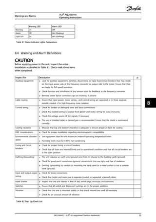
![9 Basic Troubleshooting
9.1 Start Up and Operation
Symptom Possible cause Test Solution
Display dark/No function
Missing input power See Table 3.1 Check the input power source
Missing or open fuses or circuit
breaker tripped
See open fuses and tripped circuit
breaker in this table for possible
causes
Follow the recommendations
provided
No power to the LCP Check the LCP cable for proper
connection or damage
Replace the faulty LCP or
connection cable
Shortcut on control voltage
(terminal 12 or 50) or at control
terminals
Check the 24 V control voltage
supply for terminals 12/13 to 20-39
or 10 V supply for terminals 50 to
55
Wire the terminals properly
Wrong LCP (LCP from VLT® 2800
or 5000/6000/8000/ FCD or FCM)
Use only LCP 101 (P/N 130B1124)
or LCP 102 (P/N 130B1107)
Wrong contrast setting Press [Status] + [▲]/[▼] to adjust
the contrast
Display (LCP) is defective Test using a different LCP Replace the faulty LCP or
connection cable
Internal voltage supply fault or
SMPS is defective
Contact supplier
Intermittent display
Overloaded power supply (SMPS)
due to improper control wiring or
a fault within the frequency
converter
To rule out a problem in the
control wiring, disconnect all
control wiring by removing the
terminal blocks.
If the display stays lit, then the
problem is in the control wiring.
Check the wiring for shorts or
incorrect connections. If the display
continues to cut out, follow the
procedure for display dark.
Motor not running
Service switch open or missing
motor connection
Check if the motor is connected
and the connection is not
interrupted (by a service switch or
other device).
Connect the motor and check the
service switch
No mains power with 24 V DC
option card
If the display is functioning but no
output, check that mains power is
applied to the frequency converter.
Apply mains power to run the unit
LCP Stop Check if [Off] has been pressed Press [Auto On] or [Hand On]
(depending on operation mode) to
run the motor
Missing start signal (Standby) Check 5-10 Terminal 18 Digital Input
for correct setting for terminal 18
(use default setting)
Apply a valid start signal to start
the motor
Motor coast signal active
(Coasting)
Check 5-12 Coast inv. for correct
setting for terminal 27 (use default
setting)..
Apply 24 V on terminal 27 or
program this terminal to No
operation
Wrong reference signal source Check reference signal: Local,
remote or bus reference? Preset
reference active? Terminal
connection correct? Scaling of
terminals correct? Reference signal
available?
Program correct settings. Check
3-13 Reference Site. Set preset
reference active in parameter
group 3-1* References. Check for
correct wiring. Check scaling of
terminals. Check reference signal.
Basic Troubleshooting
VLT® AQUA Drive
Operating Instructions
54 MG20M902 - VLT® is a registered Danfoss trademark
99](https://image.slidesharecdn.com/vltaquafc202-140613202655-phpapp01/85/Vlt-aqua-fc-202-58-320.jpg)
![Symptom Possible cause Test Solution
Motor running in wrong
direction
Motor rotation limit Check that 4-10 Motor Speed
Direction is programmed correctly.
Program correct settings
Active reversing signal Check if a reversing command is
programmed for the terminal in
parameter group 5-1* Digital
inputs..
Deactivate reversing signal
Wrong motor phase connection See in this manual
Motor is not reaching
maximum speed
Frequency limits set wrong Check output limits in 4-13 Motor
Speed High Limit [RPM], 4-14 Motor
Speed High Limit [Hz] and 4-19 Max
Output Frequency.
Program correct limits
Reference input signal not scaled
correctly
Check reference input signal
scaling in 6-0* Analog I/O Mode and
parameter group 3-1* References.
Reference limits in parameter
group 3-0* Reference Limit.
Program correct settings
Motor speed unstable
Possible incorrect parameter
settings
Check the settings of all motor
parameters, including all motor
compensation settings. For closed
loop operation, check PID settings.
Check settings in parameter group
1-6* Analog I/O mode. For closed
loop operation, check settings in
parameter group 20-0* Feedback..
Motor runs rough
Possible over-magnetization Check for incorrect motor settings
in all motor parameters
Check motor settings in parameter
groups 1-2* Motor Data, 1-3* Adv
Motor Data, and 1-5* Load Indep.
Setting.
Motor will not brake
Possible incorrect settings in the
brake parameters. Possible too
short ramp down times
Check brake parameters. Check
ramp time settings
Check parameter group 2-0* DC
Brake and 3-0* Reference Limits.
Open power fuses or circuit
breaker trip
Phase to phase short Motor or panel has a short phase
to phase. Check motor and panel
phase for shorts
Eliminate any shorts detected
Motor overload Motor is overloaded for the
application
Perform startup test and verify
motor current is within specifi-
cations. If motor current is
exceeding nameplate full load
current, motor may run only with
reduced load. Review the specifi-
cations for the application.
Loose connections Perform pre-startup check for loose
connections
Tighten loose connections
Mains current imbalance
greater than 3%
Problem with mains power (See
Alarm 4 Mains phase loss
description)
Rotate input power leads into the
frequency converter one position: A
to B, B to C, C to A.
If imbalanced leg follows the wire,
it is a power problem. Check mains
power supply.
Problem with the frequency
converter
Rotate input power leads into the
frequency converter one position: A
to B, B to C, C to A.
If imbalance leg stays on same
input terminal, it is a problem with
the unit. Contact the supplier.
Motor current imbalance
greater than 3%
Problem with motor or motor
wiring
Rotate output motor leads one
position: U to V, V to W, W to U.
If imbalanced leg follows the wire,
the problem is in the motor or
motor wiring. Check motor and
motor wiring.
Problem with the frequency
converters
Rotate output motor leads one
position: U to V, V to W, W to U.
If imbalance leg stays on same
output terminal, it is a problem
with the unit. Contact the supplier.
Basic Troubleshooting
VLT® AQUA Drive
Operating Instructions
MG20M902 - VLT® is a registered Danfoss trademark 55
9 9](https://image.slidesharecdn.com/vltaquafc202-140613202655-phpapp01/85/Vlt-aqua-fc-202-59-320.jpg)
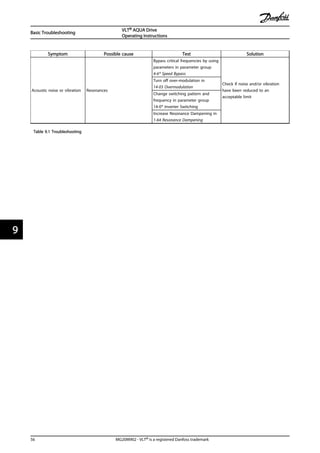
![10 Specifications
10.1 Power-dependent Specifications
10.1.1 Mains Supply 1 x 200-240 V AC
Mains Supply 1 x 200-240 V AC - Normal overload 110% for 1 minute
Frequency converter
Typical Shaft Output [kW]
P1K1
1.1
P1K5
1.5
P2K2
2.2
P3K0
3.0
P3K7
3.7
P5K5
5.5
P7K5
7.5
P15K
15
P22K
22
Typical Shaft Output [HP] at 240 V 1.5 2.0 2.9 4.0 4.9 7.5 10 20 30
IP20/Chassis A3 - - - - - - - -
IP21/NEMA 1 - B1 B1 B1 B1 B1 B2 C1 C2
IP55/NEMA 12 A5 B1 B1 B1 B1 B1 B2 C1 C2
IP66 A5 B1 B1 B1 B1 B1 B2 C1 C2
Output current
Continuous (3 x 200-240 V) [A] 6.6 7.5 10.6 12.5 16.7 24.2 30.8 59.4 88
Intermittent(3 x 200-240 V) [A] 7.3 8.3 11.7 13.8 18.4 26.6 33.4 65.3 96.8
Continuous kVA (208 V AC) [kVA] 5.00 6.40 12.27 18.30
Max. input current
Continuous (1 x 200-240 V) [A] 12.5 15 20.5 24 32 46 59 111 172
Intermittent (1 x 200-240 V) [A] 13.8 16.5 22.6 26.4 35.2 50.6 64.9 122.1 189.2
Max. pre-fuses1)[A] 20 30 40 40 60 80 100 150 200
Additional specifications
Estimated power loss at rated
max. load [W] 4)
44 30 44 60 74 110 150 300 440
Max. cable size (mains, motor, brake)
[mm2]/(AWG) 2)
[0.2-4]/(4-10) [10]/(7) [35]/(2) [50]/(1)/0 [95]/(4/0)
Weight enclosure IP20 [kg] 4.9 - - - - - - - -
Weight enclosure IP21 [kg] - 23 23 23 23 23 27 45 65
Weight enclosure IP55 [kg] - 23 23 23 23 23 27 45 65
Weight enclosure IP66 [kg] - 23 23 23 23 23 27 45 65
Efficiency 3) 0.968 0.98 0.98 0.98 0.98 0.98 0.98 0.98 0.98
Table 10.1 Mains Supply 1 x 200-240 V AC - Normal Overload 110% for 1 Minute
Specifications
VLT® AQUA Drive
Operating Instructions
MG20M902 - VLT® is a registered Danfoss trademark 57
10 10](https://image.slidesharecdn.com/vltaquafc202-140613202655-phpapp01/85/Vlt-aqua-fc-202-61-320.jpg)
![10.1.2 Mains Supply 3 x 200-240 V AC
Mains Supply 3 x 200-240 V AC - Normal overload 110% for 1 minute
Frequency converter
Typical Shaft Output [kW]
PK25
0.25
PK37
0.37
PK55
0.55
PK75
0.75
P1K1
1.1
P1K5
1.5
P2K2
2.2
P3K0
3
P3K7
3.7
Typical Shaft Output [HP] at 208 V 0.25 0.37 0.55 0.75 1.5 2.0 2.9 4.0 4.9
IP20/NEMA Chassis A2 A2 A2 A2 A2 A2 A2 A3 A3
IP21/NEMA 1 A2 A2 A2 A2 A2 A2 A2 A3 A3
IP55/NEMA 12 A5 A5 A5 A5 A5 A5 A5 A5 A5
IP66 A5 A5 A5 A5 A5 A5 A5 A5 A5
Output current
Continuous (3 x 200-240 V) [A] 1.8 2.4 3.5 4.6 6.6 7.5 10.6 12.5 16.7
Intermittent (3 x 200-240 V) [A] 1.98 2.64 3.85 5.06 7.26 8.3 11.7 13.8 18.4
Continuous kVA (208 V AC) [kVA] 0.65 0.86 1.26 1.66 2.38 2.70 3.82 4.50 6.00
Max. input current
Continuous (3 x 200-240 V) [A] 1.6 2.2 3.2 4.1 5.9 6.8 9.5 11.3 15.0
Intermittent (3 x 200-240 V) [A] 1.7 2.42 3.52 4.51 6.5 7.5 10.5 12.4 16.5
Max. pre-fuses1) [A] 10 10 10 10 20 20 20 32 32
Additional specifications
Estimated power loss at rated max. load [W] 4) 21 29 42 54 63 82 116 155 185
Max. cable size (mains, motor, brake) [mm2]/(AWG) 2) [0.2-4]/(4-10)
Weight enclosure IP20 [kg] 4.9 4.9 4.9 4.9 4.9 4.9 4.9 6.6 6.6
Weight enclosure IP21 [kg] 5.5 5.5 5.5 5.5 5.5 5.5 5.5 7.5 7.5
Weight enclosure IP55 [kg] 13.5 13.5 13.5 13.5 13.5 13.5 13.5 13.5 13.5
Weight enclosure IP66 [kg] 13.5 13.5 13.5 13.5 13.5 13.5 13.5 13.5 13.5
Efficiency 3) 0.94 0.94 0.95 0.95 0.96 0.96 0.96 0.96 0.96
Table 10.2 Mains Supply 3 x 200-240 V AC - Normal Overload 110% for 1 Minute
Specifications
VLT® AQUA Drive
Operating Instructions
58 MG20M902 - VLT® is a registered Danfoss trademark
1010](https://image.slidesharecdn.com/vltaquafc202-140613202655-phpapp01/85/Vlt-aqua-fc-202-62-320.jpg)
![Mains supply 3 x 200-240 V AC - Normal overload 110% for 1 minute
Frequency converter
Typical Shaft Output [kW]
P5K5
5.5
P7K5
7.5
P11K
11
P15K
15
P18K
18.5
P22K
22
P30K
30
P37K
37
P45K
45
Typical Shaft Output [HP] at 208 V 7.5 10 15 20 25 30 40 50 60
IP20/NEMA Chassis* B3 B3 B3 B4 B4 C3 C3 C4 C4
IP21/NEMA 1 B1 B1 B1 B2 C1 C1 C1 C2 C2
IP55/NEMA 12 B1 B1 B1 B2 C1 C1 C1 C2 C2
IP66 B1 B1 B1 B2 C1 C1 C1 C2 C2
Output current
Continuous (3 x 200-240 V) [A] 24.2 30.8 46.2 59.4 74.8 88.0 115 143 170
Intermittent (3 x 200-240 V) [A] 26.6 33.9 50.8 65.3 82.3 96.8 127 157 187
Continuous kVA (208 V AC) [kVA] 8.7 11.1 16.6 21.4 26.9 31.7 41.4 51.5 61.2
Max. input current
Continuous (3 x 200-240 V) [A] 22.0 28.0 42.0 54.0 68.0 80.0 104.0 130.0 154.0
Intermittent (3 x 200-240 V) [A] 24.2 30.8 46.2 59.4 74.8 88.0 114.0 143.0 169.0
Max. pre-fuses1) [A] 63 63 63 80 125 125 160 200 250
Additional specifications
Estimated power loss at rated
max. load [W] 4)
269 310 447 602 737 845 1140 1353 1636
Max. cable size (mains, motor,
brake)
[mm2]/(AWG) 2)
[10]/(7) [35]/(2) [50]/(1/0) [95]/(4/0)
[120]/
(250
MCM)
Weight enclosure IP20 [kg] 12 12 12 23.5 23.5 35 35 50 50
Weight enclosure IP21 [kg] 23 23 23 27 45 45 65 65 65
Weight enclosure IP55 [kg] 23 23 23 27 45 45 65 65 65
Weight enclosure IP66 [kg] 23 23 23 27 45 45 65 65 65
Efficiency 3) 0.96 0.96 0.96 0.96 0.96 0.97 0.97 0.97 0.97
Table 10.3 Mains supply 3 x 200-240 V AC - Normal Overload 110% for 1 Minute
* B3+4 and C3+4 may be converted to IP21 using a conversion kit
(contact Danfoss)
Specifications
VLT® AQUA Drive
Operating Instructions
MG20M902 - VLT® is a registered Danfoss trademark 59
10 10](https://image.slidesharecdn.com/vltaquafc202-140613202655-phpapp01/85/Vlt-aqua-fc-202-63-320.jpg)
![10.1.3 Mains Supply 1 x 380-480 V AC
Mains Supply 1 x 380 V AC - Normal overload 110% for 1 minute
Frequency converter
Typical Shaft Output [kW]
P7K5
7.5
P11K
11
P18K
18.5
P37K
37
Typical Shaft Output [HP] at 460 V 10 15 25 50
IP21/NEMA 1 B1 B2 C1 C2
IP55/NEMA 12 B1 B2 C1 C2
IP66 B1 B2 C1 C2
Output current
Continuous (3 x 380-440 V) [A] 16 24 37.5 73
Intermittent (3 x 380-440 V) [A] 17.6 26.4 41.2 80.3
Continuous (3 x 441-480 V) [A] 14.5 21 34 65
Intermittent (3 x 441-480 V) [A] 15.4 23.1 37.4 71.5
Continuous kVA (400 V AC) [kVA] 11.0 16.6 26 50.6
Continuous kVA (460 V AC) [kVA] 11.6 16.7 27.1 51.8
Max. input current
Continuous (1 x 380-440 V) [A] 33 48 78 151
Intermittent (1 x 380-440 V) [A] 36 53 85.8 166
Continuous (1 x 441-480 V [A] 30 41 72 135
Intermittent (1 x 441-480 V [A] 33 46 79.2 148
Max. pre-fuses1)[A] 63 80 160 250
Additional specifications
Estimated power loss at rated max. load [W] 4) 300 440 740 1480
Max. cable size (mains, motor, brake) [mm2]/(AWG) 2) [10]/(7) [35]/(2) [50]/(1/0) [120]/(4/0)
Weight enclosure IP21 [kg] 23 27 45 65
Weight enclosure IP55 [kg] 23 27 45 65
Weight enclosure IP66 [kg] 23 27 45 65
Efficiency 3) 0.96 0.96 0.96 0.96
Table 10.4 Mains Supply 1 x 380 V AC - Normal Overload 110% for 1 Minute
Specifications
VLT® AQUA Drive
Operating Instructions
60 MG20M902 - VLT® is a registered Danfoss trademark
1010](https://image.slidesharecdn.com/vltaquafc202-140613202655-phpapp01/85/Vlt-aqua-fc-202-64-320.jpg)
![10.1.4 Mains Supply 3 x 380-480 V AC
Mains Supply 3 x 380-480 V AC - Normal overload 110% for 1 minute
Frequency converter
Typical Shaft Output [kW]
PK37
0.37
PK55
0.55
PK75
0.75
P1K1
1.1
P1K5
1.5
P2K2
2.2
P3K0
3
P4K0
4
P5K5
5.5
P7K5
7.5
Typical Shaft Output [HP] at 460 V 0.5 0.75 1.0 1.5 2.0 2.9 4.0 5.3 7.5 10
IP20/NEMA Chassis A2 A2 A2 A2 A2 A2 A2 A2 A3 A3
IP21/NEMA 1
IP55/NEMA 12 A5 A5 A5 A5 A5 A5 A5 A5 A5 A5
IP66 A5 A5 A5 A5 A5 A5 A5 A5 AA A5
Output current
Continuous (3 x 380-440 V) [A] 1.3 1.8 2.4 3 4.1 5.6 7.2 10 13 16
Intermittent (3 x 380-440 V) [A] 1.43 1.98 2.64 3.3 4.5 6.2 7.9 11 14.3 17.6
Continuous (3 x 441-480 V) [A] 1.2 1.6 2.1 2.7 3.4 4.8 6.3 8.2 11 14.5
Intermittent (3 x 441-480 V) [A] 1.32 1.76 2.31 3.0 3.7 5.3 6.9 9.0 12.1 15.4
Continuous kVA (400 V AC) [kVA] 0.9 1.3 1.7 2.1 2.8 3.9 5.0 6.9 9.0 11.0
Continuous kVA (460 V AC) [kVA] 0.9 1.3 1.7 2.4 2.7 3.8 5.0 6.5 8.8 11.6
Max. input current
Continuous (3 x 380-440 V) [A] 1.2 1.6 2.2 2.7 3.7 5.0 6.5 9.0 11.7 14.4
Intermittent (3 x 380-440 V) [A] 1.32 1.76 2.42 3.0 4.1 5.5 7.2 9.9 12.9 15.8
Continuous (3 x 441-480 V) [A] 1.0 1.4 1.9 2.7 3.1 4.3 5.7 7.4 9.9 13.0
Intermittent (3 x 441-480 V) [A] 1.1 1.54 2.09 3.0 3.4 4.7 6.3 8.1 10.9 14.3
Max. pre-fuses1)[A] 10 10 10 10 10 20 20 20 30 30
Additional specifications
Estimated power loss at rated max. load [W] 4) 35 42 46 58 62 88 116 124 187 255
Max. cable size (mains, motor, brake)
[mm2]/(AWG) 2)
[4]/(10)
Weight enclosure IP20 [kg] 4.7 4.7 4.8 4.8 4.9 4.9 4.9 4.9 6.6 6.6
Weight enclosure IP21 [kg]
Weight enclosure IP55 [kg] 13.5 13.5 13.5 13.5 13.5 13.5 13.5 13.5 14.2 14.2
Weight enclosure IP66 [kg] 13.5 13.5 13.5 13.5 13.5 13.5 13.5 13.5 14.2 14.2
Efficiency 3) 0.93 0.95 0.96 0.96 0.97 0.97 0.97 0.97 0.97 0.97
Table 10.5 Mains Supply 3 x 380-480 V AC - Normal Overload 110% for 1 Minute
Specifications
VLT® AQUA Drive
Operating Instructions
MG20M902 - VLT® is a registered Danfoss trademark 61
10 10](https://image.slidesharecdn.com/vltaquafc202-140613202655-phpapp01/85/Vlt-aqua-fc-202-65-320.jpg)
![Mains Supply 3 x 380 - 480V AC - Normal overload 110% for 1 minute
Frequency converter
Typical Shaft Output [kW]
P11K
11
P15K
15
P18K
18.5
P22K
22
P30K
30
P37K
37
P45K
45
P55K
55
P75K
75
P90K
90
Typical Shaft Output [HP] at 460 V 15 20 25 30 40 50 60 75 100 125
IP20/NEMA Chassis * B3 B3 B3 B4 B4 B4 C3 C3 C4 C4
IP21/NEMA 1 B1 B1 B1 B2 B2 C1 C1 C1 C2 C2
IP55/NEMA 12 B1 B1 B1 B2 B2 C1 C1 C1 C2 C2
IP66 B1 B1 B1 B2 B2 C1 C1 C1 C2 C2
Output current
Continuous (3 x 380-440 V) [A] 24 32 37.5 44 61 73 90 106 147 177
Intermittent (3 x 380-440 V) [A] 26.4 35.2 41.3 48.4 67.1 80.3 99 117 162 195
Continuous (3 x 441-480 V) [A] 21 27 34 40 52 65 80 105 130 160
Intermittent (3 x 441-480 V) [A] 23.1 29.7 37.4 44 61.6 71.5 88 116 143 176
Continuous kVA (400 V AC) [kVA] 16.6 22.2 26 30.5 42.3 50.6 62.4 73.4 102 123
Continuous kVA (460 V AC) [kVA] 16.7 21.5 27.1 31.9 41.4 51.8 63.7 83.7 104 128
Max. input current
Continuous (3 x 380-440 V) [A] 22 29 34 40 55 66 82 96 133 161
Intermittent (3 x 380-440 V) [A] 24.2 31.9 37.4 44 60.5 72.6 90.2 106 146 177
Continuous (3 x 441-480 V [A] 19 25 31 36 47 59 73 95 118 145
Intermittent (3 x 441-480 V) [A] 20.9 27.5 34.1 39.6 51.7 64.9 80.3 105 130 160
Max. pre-fuses1)[A] 63 63 63 63 80 100 125 160 250 250
Additional specifications
Estimated power loss at rated
max. load [W] 4)
278 392 465 525 698 739 843 1083 1384 1474
Max. cable size (mains, motor, brake)
[mm2]/(AWG) 2)
[10]/(7) [35]/(2) [50]/(1/0)
[120]/
(4/0)
[120]/
(4/0)
Weight enclosure IP20 [kg] 12 12 12 23.5 23.5 23.5 35 35 50 50
Weight enclosure IP21 [kg] 23 23 23 27 27 45 45 45 65 65
Weight enclosure IP55 [kg] 23 23 23 27 27 45 45 45 65 65
Weight enclosure IP66 [kg] 23 23 23 27 27 45 45 45 65 65
Efficiency 3) 0.98 0.98 0.98 0.98 0.98 0.98 0.98 0.98 0.98 0.99
Table 10.6 Mains Supply 3 x 380-480 V AC - Normal Overload 110% for 1 Minute
* B3+B4 and C3+C4 may be converted to IP21 using a conversion kit
(contact Danfoss)
Specifications
VLT® AQUA Drive
Operating Instructions
62 MG20M902 - VLT® is a registered Danfoss trademark
1010](https://image.slidesharecdn.com/vltaquafc202-140613202655-phpapp01/85/Vlt-aqua-fc-202-66-320.jpg)
![10.1.5 Mains Supply 3 x 525-600 V AC
Normal overload 110% for 1 minute
Frequency converter
Typical Shaft Output [kW]
PK75
0.75
P1K1
1.1
P1K5
1.5
P2K2
2.2
P3K0
3
P4K0
4
P5K5
5.5
P7K5
7.5
P11K
11
IP20/NEMA Chassis A2 A2 A2 A2 A2 A2 A3 A3 B3
IP21/NEMA 1 A2 A2 A2 A2 A2 A2 A3 A3 B1
IP55/NEMA 12 A5 A5 A5 A5 A5 A5 A5 A5 B1
IP66 A5 A5 A5 A5 A5 A5 A5 A5 B1
Output current
Continuous (3 x 525-550 V) [A] 1.8 2.6 2.9 4.1 5.2 6.4 9.5 11.5 19
Intermittent (3 x 525-550 V) [A] 2.9 3.2 4.5 5.7 7.0 10.5 12.7 21
Continuous (3 x 525-600 V) [A] 1.7 2.4 2.7 3.9 4.9 6.1 9.0 11.0 18
Intermittent (3 x 525-600 V) [A] 2.6 3.0 4.3 5.4 6.7 9.9 12.1 20
Continuous kVA (525 V AC) [kVA] 1.7 2.5 2.8 3.9 5.0 6.1 9.0 11.0 18.1
Continuous kVA (575 V AC) [kVA] 1.7 2.4 2.7 3.9 4.9 6.1 9.0 11.0 17.9
Max. input current
Continuous (3 x 525-600 V) [A] 1.7 2.4 2.7 4.1 5.2 5.8 8.6 10.4 17.2
Intermittent (3 x 525-600 V) [A] 2.7 3.0 4.5 5.7 6.4 9.5 11.5 19
Max. pre-fuses1) [A] 10 10 10 20 20 20 32 32 40
Additional specifications
Estimated power loss at rated max. load [W] 4) 35 50 65 92 122 145 195 261 225
Max. cable size (mains, motor, brake)
[mm2]/(AWG) 2)
[0.2-4]/(24 - 10) [16]/(6)
Weight enclosure IP20 [kg] 6.5 6.5 6.5 6.5 6.5 6.5 6.6 6.6 12
Efficiency 4) 0.97 0.97 0.97 0.97 0.97 0.97 0.97 0.97 0.98
Table 10.7 Mains Supply 3 x 525-600 V AC
1) For type of fuse see 10.3.2 Fuse Tables
2) American Wire Gauge
3) Measured using 5 m screened motor cables at rated load and rated
frequency
4) The typical power loss is at normal load conditions and expected
to be within ± 15% (tolerance relates to variety in voltage and cable
conditions).
Values are based on a typical motor efficiency (eff2/eff3 border line).
Lower efficiency motors will also add to the power loss in the
frequency converter and vice versa.
If the switching frequency is raised from nominal the power losses
may rise significantly.
LCP and typical control card power consumptions are included.
Further options and customer load may add up to 30 Watts to the
losses. (Though typically only 4 W extra for a fully loaded control
card or options for slot A or slot B, each).
Although measurements are made with state of the art equipment,
some measurement inaccuracy must be allowed for (± 5%).
5) Motor and mains cable: 300 MCM/150 mm2
Specifications
VLT® AQUA Drive
Operating Instructions
MG20M902 - VLT® is a registered Danfoss trademark 63
10 10](https://image.slidesharecdn.com/vltaquafc202-140613202655-phpapp01/85/Vlt-aqua-fc-202-67-320.jpg)
![Normal overload 110% for 1 minute
Frequency converter
Typical Shaft Output [kW]
P15K
15
P18K
18.5
P22K
22
P30K
30
P37K
37
P45K
45
P55K
55
P75K
75
P90K
90
IP20/NEMA Chassis B3 B3 B4 B4 B4 C3 C3 C4 C4
IP21/NEMA 1 B1 B1 B2 B2 B2 C1 C1 C2 C2
IP55/NEMA 12 B1 B1 B2 B2 B2 C1 C1 C2 C2
IP66 B1 B1 B2 B2 B2 C1 C1 C2 C2
Output current
Continuous (3 x 525-550 V) [A] 23 28 36 43 54 65 87 105 137
Intermittent (3 x 525-550 V) [A] 25 31 40 47 59 72 96 116 151
Continuous (3 x 525-600 V) [A] 22 27 34 41 52 62 83 100 131
Intermittent (3 x 525-600 V) [A] 24 30 37 45 57 68 91 110 144
Continuous kVA (525 V AC) [kVA] 21.9 26.7 34.3 41 51.4 61.9 82.9 100 130.5
Continuous kVA (575 V AC) [kVA] 21.9 26.9 33.9 40.8 51.8 61.7 82.7 99.6 130.5
Max. input current
Continuous (3 x 525-600 V) [A] 20.9 25.4 32.7 39 49 59 78.9 95.3 124.3
Intermittent (3 x 525-600 V) [A] 23 28 36 43 54 65 87 105 137
Max. pre-fuses1) [A] 40 50 60 80 100 150 160 225 250
Additional specifications
Estimated power loss at rated max. load [W] 4) 285 329 460 560 740 860 890 1020 1130
Max. cable size (mains, motor, brake)
[mm2]/(AWG) 2)
[35]/(2) [50]/(1) [95 5)]/( 3/0)
Weight enclosure IP20 [kg] 12 12 23.5 23.5 23.5 35 35 50 50
Efficiency 4) 0.98 0.98 0.98 0.98 0.98 0.98 0.98 0.98 0.98
Table 10.8 Mains Supply 3 x 525-600 V AC
1) For type of fuse see 10.3.2 Fuse Tables
2) American Wire Gauge
3) Measured using 5 m screened motor cables at rated load and rated
frequency
4) The typical power loss is at normal load conditions and expected
to be within ± 15% (tolerance relates to variety in voltage and cable
conditions).
Values are based on a typical motor efficiency (eff2/eff3 border line).
Lower efficiency motors will also add to the power loss in the
frequency converter and vice versa.
If the switching frequency is raised from nominal the power losses
may rise significantly.
LCP and typical control card power consumptions are included.
Further options and customer load may add up to 30 Watts to the
losses. (Though typically only 4 W extra for a fully loaded control
card or options for slot A or slot B, each).
Although measurements are made with state of the art equipment,
some measurement inaccuracy must be allowed for (± 5%).
5) Motor and mains cable: 300 MCM/150 mm2
Specifications
VLT® AQUA Drive
Operating Instructions
64 MG20M902 - VLT® is a registered Danfoss trademark
1010](https://image.slidesharecdn.com/vltaquafc202-140613202655-phpapp01/85/Vlt-aqua-fc-202-68-320.jpg)
![10.1.6 Mains Supply 3 x 525-690 V AC
Mains Supply 3x525-690 V AC
Frequency Converter
Typical Shaft Output [kW]
P1K1
1.1
P1K5
1.5
P2K2
2.2
P3K0
3
P4K0
4
P5K5
5.5
P7K5
7.5
Enclosure IP20 (only) A3 A3 A3 A3 A3 A3 A3
Output current High overload 110% for 1 min
Continuous (3x525-550 V) [A] 2.1 2.7 3.9 4.9 6.1 9 11
Intermittent (3x525-550 V) [A] 2.3 3.0 4.3 5.4 6.7 9.9 12.1
Continuous kVA (3x551-690 V) [A] 1.6 2.2 3.2 4.5 5.5 7.5 10
Intermittent kVA (3x551-690 V) [A] 1.8 2.4 3.5 4.9 6.0 8.2 11
Continuous kVA 525 V AC 1.9 2.6 3.8 5.4 6.6 9 12
Continuous kVA 690 V AC 1.9 2.6 3.8 5.4 6.6 9 12
Max. input current
Continuous (3x525-550 V) [A] 1.9 2.4 3.5 4.4 5.5 8 10
Intermittent (3x525-550 V) [A] 2.1 2.6 3.8 8.4 6.0 8.8 11
Continuous kVA (3x551-690 V) [A] 1.4 2.0 2.9 4.0 4.9 6.7 9
Intermittent kVA (3x551-690 V) [A] 1.5 2.2 3.2 4.4 5.4 7.4 9.9
Additional specifications
IP20 max. cable cross section5) (mains, motor,
brake and load sharing) [mm2]/(AWG)
[0.2-4]/(24-10)
Estimated power loss at rated max. load [W] 4) 44 60 88 120 160 220 300
Weight, enclosure IP20 [kg] 6.6 6.6 6.6 6.6 6.6 6.6 6.6
Efficiency 4) 0.96 0.96 0.96 0.96 0.96 0.96 0.96
Table 10.9 Mains Supply 3 x 525-690 V AC IP20
Specifications
VLT® AQUA Drive
Operating Instructions
MG20M902 - VLT® is a registered Danfoss trademark 65
10 10](https://image.slidesharecdn.com/vltaquafc202-140613202655-phpapp01/85/Vlt-aqua-fc-202-69-320.jpg)
![Normal overload 110% for 1 minute
Frequency converter
TypicalShaft Output [kW]
P11K
11
P15K
15
P18K
18.5
P22K
22
P30K
30
P37K
37
P45K
45
P55K
55
P75K
75
P90K
90
Typical Shaft Output [HP] at
575 V
10 16.4 20.1 24 33 40 50 60 75 100
IP21/NEMA 1 B2 B2 B2 B2 B2 C2 C2 C2 C2 C2
IP55/NEMA 12 B2 B2 B2 B2 B2 C2 C2 C2 C2 C2
Output current
Continuous (3 x 525-550 V)
[A]
14 19 23 28 36 43 54 65 87 105
Intermittent (3 x 525-550 V)
[A]
15.4 20.9 25.3 30.8 39.6 47.3 59.4 71.5 95.7 115.5
Continuous (3 x 551-690 V)
[A]
13 18 22 27 34 41 52 62 83 100
Intermittent (3 x 551-690 V)
[A]
14.3 19.8 24.2 29.7 37.4 45.1 57.2 68.2 91.3 110
Continuous kVA (550 V AC)
[kVA]
13.3 18.1 21.9 26.7 34.3 41 51.4 61.9 82.9 100
Continuous kVA (575 V AC)
[kVA]
12.9 17.9 21.9 26.9 33.8 40.8 51.8 61.7 82.7 99.6
Continuous kVA (690 V AC)
[kVA]
15.5 21.5 26.3 32.3 40.6 49 62.1 74.1 99.2 119.5
Max. input current
Continuous (3 x 525-690 V)
[A]
15 19.5 24 29 36 49 59 71 87 99
Intermittent (3 x 525-690 V)
[A]
16.5 21.5 26.4 31.9 39.6 53.9 64.9 78.1 95.7 108.9
Max. pre-fuses1) [A] 63 63 63 63 80 100 125 160 160 160
Additional specifications
Estimated power loss at
rated max. load [W] 4)
201 285 335 375 430 592 720 880 1200 1440
Max. cable size (mains,
motor, brake) [mm2]/(AWG)
2)
[35]/(1/0) [95]/(4/0)
Weight IP21 [kg] 27 27 27 27 27 65 65 65 65 65
Weight IP55 [kg] 27 27 27 27 27 65 65 65 65 65
Efficiency 4) 0.98 0.98 0.98 0.98 0.98 0.98 0.98 0.98 0.98 0.98
Table 10.10 Mains Supply 3 x 525-690 V AC IP21-IP55/NEMA 1-NEMA 12
Specifications
VLT® AQUA Drive
Operating Instructions
66 MG20M902 - VLT® is a registered Danfoss trademark
1010](https://image.slidesharecdn.com/vltaquafc202-140613202655-phpapp01/85/Vlt-aqua-fc-202-70-320.jpg)
![Normal overload 110% for 1 minute
Frequency converter
Typical Shaft Output [kW]
P45K
45
P55K
55
Typical Shaft Output [HP] at 575 V 60 75
IP20/Chassis C3 C3
Output current
Continuous (3 x 525-550 V) [A] 54 65
Intermittent (3 x 525-550 V) [A] 59.4 71.5
Continuous (3 x 551-690 V) [A] 52 62
Intermittent (3 x 551-690 V) [A] 57.2 68.2
Continuous kVA (550 V AC) [kVA] 51.4 62
Continuous kVA (575 V AC) [kVA] 62.2 74.1
Continuous kVA (690 V AC) [kVA] 62.2 74.1
Max. input current
Continuous (3 x 525-550 V) [A] 52 63
Intermittent (3 x 525-550 V) [A] 57.2 69.3
Continuous (3 x 551-690 V) [A] 50 60
Intermittent (3 x 551-690 V) [A] 55 66
Max. pre-fuses1) [A] 100 125
Additional specifications
Estimated power loss at rated max. load [W] 4) 592 720
Max. cable size (mains, motor, brake) [mm2]/(AWG) 2) 50 (1)
Weight IP20 [kg] 35 35
Efficiency 4) 0.98 0.98
Table 10.11 Mains Supply 3 x 525-690 V IP20
1) For type of fuse see 10.3.2 Fuse Tables
2) American Wire Gauge
3) Measured using 5 m screened motor cables at rated load and rated
frequency
4) The typical power loss is at normal load conditions and expected
to be within ±15% (tolerance relates to variety in voltage and cable
conditions).
Values are based on a typical motor efficiency (eff2/eff3 border line).
Lower efficiency motors will also add to the power loss in the
frequency converter and vice versa.
If the switching frequency is raised from nominal the power losses
may rise significantly.
LCP and typical control card power consumptions are included.
Further options and customer load may add up to 30 W to the
losses. (Though typically only 4 W extra for a fully loaded control
card or options for slot A or slot B, each).
Although measurements are made with state of the art equipment,
some measurement inaccuracy must be allowed for (±5%).
5) Motor and mains cable: 300 MCM/150 mm2
Specifications
VLT® AQUA Drive
Operating Instructions
MG20M902 - VLT® is a registered Danfoss trademark 67
10 10](https://image.slidesharecdn.com/vltaquafc202-140613202655-phpapp01/85/Vlt-aqua-fc-202-71-320.jpg)
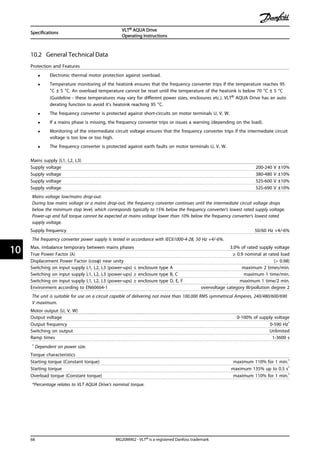
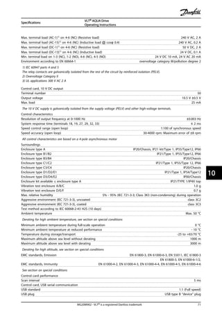
![10.3 Fuse Specifications
10.3.1 CE Compliance
Fuses or Circuit Breakers are mandatory to comply with IEC
60364. Danfoss recommend using a selection of the
following.
The fuses below are suitable for use on a circuit capable of
delivering 100,000 Arms (symmetrical) with the following
voltage
• 240 V
• 480 V
• 600 V
• 690 V
depending on the drive voltage rating. With the proper
fusing the drive Short Circuit Current Rating (SCCR) is
100,000 Arms.
10.3.2 Fuse Tables
Enclosure Power [kW] Recommended
fuse size
Recommended
Max. fuse
Recommended circuit
breaker
Moeller
Max trip level [A]
A1 - gG-10 gG-25 PKZM0-16 16
A2 0.25-2.2 gG-10 (0.25-1.5)
gG-16 (2.2)
gG-25 PKZM0-25 25
A3 3.0-3.7 gG-16 (3)
gG-20 (3.7)
gG-32 PKZM0-25 25
A4 0.25-2.2 gG-10 (0.25-1.5)
gG-16 (2.2)
gG-32 PKZM0-25 25
A5 0.25-3.7 gG-10 (0.25-1.5)
gG-16 (2.2-3)
gG-20 (3.7)
gG-32 PKZM0-25 25
B1 5.5-11 gG-25 (5.5)
gG-32 (7.5)
gG-80 PKZM4-63 63
B2 15 gG-50 gG-100 NZMB1-A100 100
B3 5.5-11 gG-25 gG-63 PKZM4-50 50
B4 15-18 gG-32 (7.5)
gG-50 (11)
gG-63 (15)
gG-125 NZMB1-A100 100
C1 18.5-30 gG-63 (15)
gG-80 (18.5)
gG-100 (22)
gG-160 (15-18.5)
aR-160 (22)
NZMB2-A200 160
C2 37-45 aR-160 (30)
aR-200 (37)
aR-200 (30)
aR-250 (37)
NZMB2-A250 250
C3 22-30 gG-80 (18.5)
aR-125 (22)
gG-150 (18.5)
aR-160 (22)
NZMB2-A200 150
C4 37-45 aR-160 (30)
aR-200 (37)
aR-200 (30)
aR-250 (37)
NZMB2-A250 250
Table 10.12 200-240 V, Frame Sizes A, B and C
Specifications
VLT® AQUA Drive
Operating Instructions
MG20M902 - VLT® is a registered Danfoss trademark 73
10 10](https://image.slidesharecdn.com/vltaquafc202-140613202655-phpapp01/85/Vlt-aqua-fc-202-77-320.jpg)
![Enclosure Power [kW] Recommended
fuse size
Recommended
Max. fuse
Recommended circuit
breaker
Moeller
Max trip level [A]
A1 - gG-10 gG-25 PKZM0-16 16
A2 1.1-4.0 gG-10 (0.37-3)
gG-16 (4)
gG-25 PKZM0-25 25
A3 5.5-7.5 gG-16 gG-32 PKZM0-25 25
A4 1.1-4.0 gG-10 (0.37-3)
gG-16 (4)
gG-32 PKZM0-25 25
A5 1.1-7.5 gG-10 (0.37-3)
gG-16 (4-7.5)
gG-32 PKZM0-25 25
B1 11-18.5 gG-40 gG-80 PKZM4-63 63
B2 22-30 gG-50 (18.5)
gG-63 (22)
gG-100 NZMB1-A100 100
B3 11-18 gG-40 gG-63 PKZM4-50 50
B4 22-37 gG-50 (18.5)
gG-63 (22)
gG-80 (30)
gG-125 NZMB1-A100 100
C1 37-55 gG-80 (30)
gG-100 (37)
gG-160 (45)
gG-160 NZMB2-A200 160
C2 75-90 aR-200 (55)
aR-250 (75)
aR-250 NZMB2-A250 250
C3 45-55 gG-100 (37)
gG-160 (45)
gG-150 (37)
gG-160 (45)
NZMB2-A200 150
C4 75-90 aR-200 (55)
aR-250 (75)
aR-250 NZMB2-A250 250
Table 10.13 380-480 V, Frame Sizes A, B and C
Specifications
VLT® AQUA Drive
Operating Instructions
74 MG20M902 - VLT® is a registered Danfoss trademark
1010](https://image.slidesharecdn.com/vltaquafc202-140613202655-phpapp01/85/Vlt-aqua-fc-202-78-320.jpg)
![Enclosure Power [kW] Recommended
fuse size
Recommended
Max. fuse
Recommended circuit
breaker
Moeller
Max trip level [A]
A2 1.1-4.0 gG-10 gG-25 PKZM0-25 25
A3 5.5-7.5 gG-10 (5.5)
gG-16 (7.5)
gG-32 PKZM0-25 25
A5 1.1-7.5 gG-10 (0.75-5.5)
gG-16 (7.5)
gG-32 PKZM0-25 25
B1 11-18 gG-25 (11)
gG-32 (15)
gG-40 (18.5)
gG-80 PKZM4-63 63
B2 22-30 gG-50 (22)
gG-63 (30)
gG-100 NZMB1-A100 100
B3 11-18.5 gG-25 (11)
gG-32 (15)
gG-63 PKZM4-50 50
B4 22-37 gG-40 (18.5)
gG-50 (22)
gG-63 (30)
gG-125 NZMB1-A100 100
C1 37-55 gG-63 (37)
gG-100 (45)
aR-160 (55)
gG-160 (37-45)
aR-250 (55)
NZMB2-A200 160
C2 75-90 aR-200 (75) aR-250 NZMB2-A250 250
C3 45-55 gG-63 (37)
gG-100 (45)
gG-150 NZMB2-A200 150
C4 75-90 aR-160 (55)
aR-200 (75)
aR-250 NZMB2-A250 250
Table 10.14 525-600 V, Frame Sizes A, B and C
Enclosure Power [kW] Recommended fuse size Recommended max. fuse Recommended circuit
breaker
Danfoss
Max trip level[A]
A3
1.1 gG-6 gG-25 CTI25M 10-16 16
1.5 gG-6 gG-25 CTI25M 10-16 16
2.2 gG-6 gG-25 CTI25M 10-16 16
3 gG-10 gG-25 CTI25M 10-16 16
4 gG-10 gG-25 CTI25M 10-16 16
5.5 gG-16 gG-25 CTI25M 10-16 16
7.5 gG-16 gG-25 CTI25M 10-16 16
B2
11 gG-25 gG-63
15 gG-25 gG-63
18 gG-32
22 gG-32
C2
30 gG-40
37 gG-63 gG-80
45 gG-63 gG-100
55 gG-80 gG-125
75 gG-100 gG-160
C3
37 gG-100 gG-125
45 gG-125 gG-160
D
37 gG-125 gG-125
45 gG-160 gG-160
55-75 gG-200 gG-200
90 aR-250 aR-250
Table 10.15 525-690 V, Frame Sizes A, C and D (non UL fuses)
Specifications
VLT® AQUA Drive
Operating Instructions
MG20M902 - VLT® is a registered Danfoss trademark 75
10 10](https://image.slidesharecdn.com/vltaquafc202-140613202655-phpapp01/85/Vlt-aqua-fc-202-79-320.jpg)
![10.3.3 UL Compliance
Fuses or Circuit Breakers are mandatory to comply with UL
for NEC 2009. We recommend using a selection of the
following
The fuses below are suitable for use on a circuit capable of
delivering 100,000 Arms (symmetrical) with the following
voltage
• 240 V
• 480 V
• 600 V
• 690 V
depending on the drive voltage rating. With the proper
fusing the drive Short Circuit Current Rating (SCCR) is
100,000 Arms.
Recommended max. fuse
Power
[kW]
Max prefuse
size [A]
Buss-
mann
JFHR2
Buss-
mann
RK1
Buss-
mann
J
Buss-
mann
T
Buss-
mann
CC
Buss-
mann
CC
Buss-
mann
CC
SIBA
RK1
Littel
fuse
RK1
Ferraz-
Shawmut
CC
Ferraz-
Shawmut
RK1
Ferraz-
Shawmut
J
1.1 15
FWX-1
5
KTN-
R15 JKS-15 JJN-15
FNQ-
R-15
KTK-
R-15
LP-
CC-15
501790
6-016
KLN-
R15 ATM-R15 A2K-15R HSJ15
1.5 20
FWX-2
0
KTN-
R20 JKS-20 JJN-20
FNQ-
R-20
KTK-
R-20
LP-
CC-20
501790
6-020
KLN-
R20 ATM-R20 A2K-20R HSJ20
2.2 30*
FWX-3
0
KTN-
R30 JKS-30 JJN-30
FNQ-
R-30
KTK-
R-30
LP-
CC-30
501240
6-032
KLN-
R30 ATM-R30 A2K-30R HSJ30
3.0 35
FWX-3
5
KTN-
R35 JKS-35 JJN-35 ---
KLN-
R35 --- A2K-35R HSJ35
3.7 50
FWX-5
0
KTN-
R50 JKS-50 JJN-50
501400
6-050
KLN-
R50 --- A2K-50R HSJ50
5.5 60**
FWX-6
0
KTN-
R60 JKS-60 JJN-60
501400
6-063
KLN-
R60 --- A2K-60R HSJ60
7.5 80
FWX-8
0
KTN-
R80 JKS-80 JJN-80
501400
6-080
KLN-
R80 --- A2K-80R HSJ80
15 150
FWX-1
50
KTN-
R150
JKS-15
0
JJN-15
0
202822
0-150
KLN-
R150 A2K-150R HSJ150
22 200
FWX-2
00
KTN-
R200
JKS-20
0
JJN-20
0
202822
0-200
KLN-
R200 A2K-200R HSJ200
Table 10.16 1 x 200-240 V
* Siba allowed up to 32 A
** Siba allowed up to 63 A
Recommended max. fuse
Power
[kW]
Max prefuse
size [A]
Buss-
mann
JFHR2
Buss-
mann
RK1
Buss-
mann
J
Buss-
mann
T
Buss-
mann
CC
Buss-
mann
CC
Buss-
mann
CC
SIBA
RK1
Littel
fuse
RK1
Ferraz-
Shawmut
CC
Ferraz-
Shawmut
RK1
Ferraz-
Shawmut
J
7.5 60
FWH-6
0
KTS-
R60 JKS-60 JJS-60
501400
6-063
KLS-
R60 - A6K-60R HSJ60
11 80
FWH-8
0
KTS-
R80 JKS-80 JJS-80
202822
0-100
KLS-
R80 - A6K-80R HSJ80
22 150
FWH-1
50
KTS-
R150
JKS-15
0
JJS-15
0
202822
0-160
KLS-
R150 - A6K-150R HSJ150
37 200
FWH-2
00
KTS-
R200
JKS-20
0
JJS-20
0
202822
0-200
KLS-20
0 A6K-200R HSJ200
Table 10.17 1 x 380-500 V
KTS-fuses from Bussmann may substitute KTN for 240 V frequency converters
FWH-fuses from Bussmann may substitute FWX for 240 V frequency converters
JJS-fuses from Bussmann may substitute JJN for 240 V frequency converters
KLSR fuses from LITTLE FUSES may substitute KLNR fuses for 240 V frequency converters
A6KR fuses from FERRAZ SHAWMUT may substitute A2KR for 240 V frequency converters
Specifications
VLT® AQUA Drive
Operating Instructions
76 MG20M902 - VLT® is a registered Danfoss trademark
1010](https://image.slidesharecdn.com/vltaquafc202-140613202655-phpapp01/85/Vlt-aqua-fc-202-80-320.jpg)
![Recommended max. fuse
Power
[kW]
Bussmann
Type RK1 1)
Bussmann
Type J
Bussmann
Type T
Bussmann
Type CC
Bussmann Bussmann
Type CC
0.25-0.37 KTN-R-05 JKS-05 JJN-05 FNQ-R-5 KTK-R-5 LP-CC-5
0.55-1.1 KTN-R-10 JKS-10 JJN-10 FNQ-R-10 KTK-R-10 LP-CC-10
1.5 KTN-R-15 JKS-15 JJN-15 FNQ-R-15 KTK-R-15 LP-CC-15
2.2 KTN-R-20 JKS-20 JJN-20 FNQ-R-20 KTK-R-20 LP-CC-20
3.0 KTN-R-25 JKS-25 JJN-25 FNQ-R-25 KTK-R-25 LP-CC-25
3.7 KTN-R-30 JKS-30 JJN-30 FNQ-R-30 KTK-R-30 LP-CC-30
5.5-7.5 KTN-R-50 KS-50 JJN-50 - - -
11 KTN-R-60 JKS-60 JJN-60 - - -
15 KTN-R-80 JKS-80 JJN-80 - - -
18.5-22 KTN-R-125 JKS-125 JJN-125 - - -
30 KTN-R-150 JKS-150 JJN-150 - - -
37 KTN-R-200 JKS-200 JJN-200 - - -
45 KTN-R-250 JKS-250 JJN-250 - - -
Table 10.18 3 x 200-240 V, Frame Sizes A, B and C
Recommended max. fuse
Power
[kW]
SIBA
Type RK1
Littel fuse
Type RK1
Ferraz-
Shawmut
Type CC
Ferraz-
Shawmut
Type RK13)
0.25-0.37 5017906-005 KLN-R-05 ATM-R-05 A2K-05-R
0.55-1.1 5017906-010 KLN-R-10 ATM-R-10 A2K-10-R
1.5 5017906-016 KLN-R-15 ATM-R-15 A2K-15-R
2.2 5017906-020 KLN-R-20 ATM-R-20 A2K-20-R
3.0 5017906-025 KLN-R-25 ATM-R-25 A2K-25-R
3.7 5012406-032 KLN-R-30 ATM-R-30 A2K-30-R
5.5-7.5 5014006-050 KLN-R-50 - A2K-50-R
11 5014006-063 KLN-R-60 - A2K-60-R
15 5014006-080 KLN-R-80 - A2K-80-R
18.5-22 2028220-125 KLN-R-125 - A2K-125-R
30 2028220-150 KLN-R-150 - A2K-150-R
37 2028220-200 KLN-R-200 - A2K-200-R
45 2028220-250 KLN-R-250 - A2K-250-R
Table 10.19 3 x 200-240 V, Frame Sizes A, B and C
Specifications
VLT® AQUA Drive
Operating Instructions
MG20M902 - VLT® is a registered Danfoss trademark 77
10 10](https://image.slidesharecdn.com/vltaquafc202-140613202655-phpapp01/85/Vlt-aqua-fc-202-81-320.jpg)
![Recommended max. fuse
Power
[kW]
Bussmann
Type JFHR22)
Littel fuse
JFHR2
Ferraz-
Shawmut
JFHR24)
Ferraz-
Shawmut
J
0.25-0.37 FWX-5 - - HSJ-6
0.55-1.1 FWX-10 - - HSJ-10
1.5 FWX-15 - - HSJ-15
2.2 FWX-20 - - HSJ-20
3.0 FWX-25 - - HSJ-25
3.7 FWX-30 - - HSJ-30
5.5-7.5 FWX-50 - - HSJ-50
11 FWX-60 - - HSJ-60
15 FWX-80 - - HSJ-80
18.5-22 FWX-125 - - HSJ-125
30 FWX-150 L25S-150 A25X-150 HSJ-150
37 FWX-200 L25S-200 A25X-200 HSJ-200
45 FWX-250 L25S-250 A25X-250 HSJ-250
Table 10.20 3 x 200-240 V, Frame Sizes A, B and C
1) KTS-fuses from Bussmann may substitute KTN for 240 V frequency converters.
2) FWH-fuses from Bussmann may substitute FWX for 240 V frequency converters.
3) A6KR fuses from FERRAZ SHAWMUT may substitute A2KR for 240 V frequency converters.
4) A50X fuses from FERRAZ SHAWMUT may substitute A25X for 240 V frequency converters.
Recommended max. fuse
Power
[kW]
Bussmann
Type RK1
Bussmann
Type J
Bussmann
Type T
Bussmann
Type CC
Bussmann
Type CC
Bussmann
Type CC
- KTS-R-6 JKS-6 JJS-6 FNQ-R-6 KTK-R-6 LP-CC-6
1.1-2.2 KTS-R-10 JKS-10 JJS-10 FNQ-R-10 KTK-R-10 LP-CC-10
3 KTS-R-15 JKS-15 JJS-15 FNQ-R-15 KTK-R-15 LP-CC-15
4 KTS-R-20 JKS-20 JJS-20 FNQ-R-20 KTK-R-20 LP-CC-20
5.5 KTS-R-25 JKS-25 JJS-25 FNQ-R-25 KTK-R-25 LP-CC-25
7.5 KTS-R-30 JKS-30 JJS-30 FNQ-R-30 KTK-R-30 LP-CC-30
11 KTS-R-40 JKS-40 JJS-40 - - -
15 KTS-R-50 JKS-50 JJS-50 - - -
22 KTS-R-60 JKS-60 JJS-60 - - -
30 KTS-R-80 JKS-80 JJS-80 - - -
37 KTS-R-100 JKS-100 JJS-100 - - -
45 KTS-R-125 JKS-125 JJS-125 - - -
55 KTS-R-150 JKS-150 JJS-150 - - -
75 KTS-R-200 JKS-200 JJS-200 - - -
90 KTS-R-250 JKS-250 JJS-250 - - -
Table 10.21 3 x 380-480 V, Frame Sizes A, B and C
Specifications
VLT® AQUA Drive
Operating Instructions
78 MG20M902 - VLT® is a registered Danfoss trademark
1010](https://image.slidesharecdn.com/vltaquafc202-140613202655-phpapp01/85/Vlt-aqua-fc-202-82-320.jpg)
![Recommended max. fuse
Power [kW] SIBA
Type RK1
Littel fuse
Type RK1
Ferraz-
Shawmut
Type CC
Ferraz-
Shawmut
Type RK1
- 5017906-006 KLS-R-6 ATM-R-6 A6K-6-R
1.1-2.2 5017906-010 KLS-R-10 ATM-R-10 A6K-10-R
3 5017906-016 KLS-R-15 ATM-R-15 A6K-15-R
4 5017906-020 KLS-R-20 ATM-R-20 A6K-20-R
5.5 5017906-025 KLS-R-25 ATM-R-25 A6K-25-R
7.5 5012406-032 KLS-R-30 ATM-R-30 A6K-30-R
11 5014006-040 KLS-R-40 - A6K-40-R
15 5014006-050 KLS-R-50 - A6K-50-R
22 5014006-063 KLS-R-60 - A6K-60-R
30 2028220-100 KLS-R-80 - A6K-80-R
37 2028220-125 KLS-R-100 - A6K-100-R
45 2028220-125 KLS-R-125 - A6K-125-R
55 2028220-160 KLS-R-150 - A6K-150-R
75 2028220-200 KLS-R-200 - A6K-200-R
90 2028220-250 KLS-R-250 - A6K-250-R
Table 10.22 3 x 380-480 V, Frame Sizes A, B and C
Recommended max. fuse
Power [kW] Bussmann
JFHR2
Ferraz- Shawmut
J
Ferraz- Shawmut
JFHR21)
Littel fuse
JFHR2
- FWH-6 HSJ-6 - -
1.1-2.2 FWH-10 HSJ-10 - -
3 FWH-15 HSJ-15 - -
4 FWH-20 HSJ-20 - -
5.5 FWH-25 HSJ-25 - -
7.5 FWH-30 HSJ-30 - -
11 FWH-40 HSJ-40 - -
15 FWH-50 HSJ-50 - -
22 FWH-60 HSJ-60 - -
30 FWH-80 HSJ-80 - -
37 FWH-100 HSJ-100 - -
45 FWH-125 HSJ-125 - -
55 FWH-150 HSJ-150 - -
75 FWH-200 HSJ-200 A50-P-225 L50-S-225
90 FWH-250 HSJ-250 A50-P-250 L50-S-250
Table 10.23 3 x 380-480 V, Frame Sizes A, B and C
1) Ferraz-Shawmut A50QS fuses may substitute for A50P fuses.
Specifications
VLT® AQUA Drive
Operating Instructions
MG20M902 - VLT® is a registered Danfoss trademark 79
10 10](https://image.slidesharecdn.com/vltaquafc202-140613202655-phpapp01/85/Vlt-aqua-fc-202-83-320.jpg)
![Recommended max. fuse
Power [kW] Bussmann
Type RK1
Bussmann
Type J
Bussmann
Type T
Bussmann
Type CC
Bussmann
Type CC
Bussmann
Type CC
0.75-1.1 KTS-R-5 JKS-5 JJS-6 FNQ-R-5 KTK-R-5 LP-CC-5
1.5-2.2 KTS-R-10 JKS-10 JJS-10 FNQ-R-10 KTK-R-10 LP-CC-10
3 KTS-R15 JKS-15 JJS-15 FNQ-R-15 KTK-R-15 LP-CC-15
4 KTS-R20 JKS-20 JJS-20 FNQ-R-20 KTK-R-20 LP-CC-20
5.5 KTS-R-25 JKS-25 JJS-25 FNQ-R-25 KTK-R-25 LP-CC-25
7.5 KTS-R-30 JKS-30 JJS-30 FNQ-R-30 KTK-R-30 LP-CC-30
11-15 KTS-R-35 JKS-35 JJS-35 - - -
18 KTS-R-45 JKS-45 JJS-45 - - -
22 KTS-R-50 JKS-50 JJS-50 - - -
30 KTS-R-60 JKS-60 JJS-60 - - -
37 KTS-R-80 JKS-80 JJS-80 - - -
45 KTS-R-100 JKS-100 JJS-100 - - -
55 KTS-R-125 JKS-125 JJS-125 - - -
75 KTS-R-150 JKS-150 JJS-150 - - -
90 KTS-R-175 JKS-175 JJS-175 - - -
Table 10.24 3 x 525-600 V, Frame Sizes A, B and C
Recommended max. fuse
Power [kW] SIBA
Type RK1
Littel fuse
Type RK1
Ferraz-
Shawmut
Type RK1
Ferraz-
Shawmut
J
0.75-1.1 5017906-005 KLS-R-005 A6K-5-R HSJ-6
1.5-2.2 5017906-010 KLS-R-010 A6K-10-R HSJ-10
3 5017906-016 KLS-R-015 A6K-15-R HSJ-15
4 5017906-020 KLS-R-020 A6K-20-R HSJ-20
5.5 5017906-025 KLS-R-025 A6K-25-R HSJ-25
7.5 5017906-030 KLS-R-030 A6K-30-R HSJ-30
11-15 5014006-040 KLS-R-035 A6K-35-R HSJ-35
18 5014006-050 KLS-R-045 A6K-45-R HSJ-45
22 5014006-050 KLS-R-050 A6K-50-R HSJ-50
30 5014006-063 KLS-R-060 A6K-60-R HSJ-60
37 5014006-080 KLS-R-075 A6K-80-R HSJ-80
45 5014006-100 KLS-R-100 A6K-100-R HSJ-100
55 2028220-125 KLS-R-125 A6K-125-R HSJ-125
75 2028220-150 KLS-R-150 A6K-150-R HSJ-150
90 2028220-200 KLS-R-175 A6K-175-R HSJ-175
Table 10.25 3 x 525-600 V, Frame Sizes A, B and C
1) 170M fuses shown from Bussmann use the -/80 visual indicator. –TN/80 Type T, -/110 or TN/110 Type T indicator fuses of the same size and
amperage may be substituted.
Specifications
VLT® AQUA Drive
Operating Instructions
80 MG20M902 - VLT® is a registered Danfoss trademark
1010](https://image.slidesharecdn.com/vltaquafc202-140613202655-phpapp01/85/Vlt-aqua-fc-202-84-320.jpg)
![Recommended max. fuse
Power
[kW]
Max.
prefuse
[A]
Bussmann
E52273
RK1/JDDZ
Bussmann
E4273
J/JDDZ
Bussmann
E4273
T/JDDZ
SIBA
E180276
RK1/JDDZ
LittelFuse
E81895
RK1/JDDZ
Ferraz-
Shawmut
E163267/E2137
RK1/JDDZ
Ferraz-
Shawmut
E2137
J/HSJ
11-15 30 KTS-R-30 JKS-30 JKJS-30 5017906-030 KLS-R-030 A6K-30-R HST-30
22 45 KTS-R-45 JKS-45 JJS-45 5014006-050 KLS-R-045 A6K-45-R HST-45
30 60 KTS-R-60 JKS-60 JJS-60 5014006-063 KLS-R-060 A6K-60-R HST-60
37 80 KTS-R-80 JKS-80 JJS-80 5014006-080 KLS-R-075 A6K-80-R HST-80
45 90 KTS-R-90 JKS-90 JJS-90 5014006-100 KLS-R-090 A6K-90-R HST-90
55 100 KTS-R-100 JKS-100 JJS-100 5014006-100 KLS-R-100 A6K-100-R HST-100
75 125 KTS-R-125 JKS-125 JJS-125 2028220-125 KLS-150 A6K-125-R HST-125
90 150 KTS-R-150 JKS-150 JJS-150 2028220-150 KLS-175 A6K-150-R HST-150
* UL compliance 525-600 V only
Table 10.26 3 x 525-690 V*, Frame Sizes B and C
10.4 Connection Tightening Torques
Power (kW) Torque (Nm)
Enclo-
sure
200-240 V
380-480/500
V
525-600 V 525-690 V Mains Motor
DC
connecti
on
Brake Earth Relay
A2 0.25-2.2 0.37-4.0 1.8 1.8 1.8 1.8 3 0.6
A3 3.0-3.7 5.5-7.5 0.75-7.5 1.1-7.5 1.8 1.8 1.8 1.8 3 0.6
A4 0.25-2.2 0.37-4.0 1.8 1.8 1.8 1.8 3 0.6
A5 0.25-3.7 0.37-7.5 0.75-7.5 1.8 1.8 1.8 1.8 3 0.6
B1 5.5-7.5 11-15 11-15 1.8 1.8 1.5 1.5 3 0.6
B2 11
18
22
18
22
11
22
4.5
4.5
4.5
4.5
3.7
3.7
3.7
3.7
3
3
0.6
0.6
B3 5.5 -7.5 11-15 11-15 1.8 1.8 1.8 1.8 3 0.6
B4 11-15 18-30 18-30 4.5 4.5 4.5 4.5 3 0.6
C1 15-22 30-45 30-45 10 10 10 10 3 0.6
C2 30-37 55 -75 55-75 30-75 14/241) 14/241) 14 14 3 0.6
C3 18-22 37-45 37-45 45-55 10 10 10 10 3 0.6
C4 30-37 55-75 55-75 14/24 1) 14/24 1) 14 14 3 0.6
Table 10.27 Tightening of Terminals
1) For different cable dimensions x/y, where x ≤ 95 mm2 and y ≥ 95 mm2.
Specifications
VLT® AQUA Drive
Operating Instructions
MG20M902 - VLT® is a registered Danfoss trademark 81
10 10](https://image.slidesharecdn.com/vltaquafc202-140613202655-phpapp01/85/Vlt-aqua-fc-202-85-320.jpg)

This document provides operating instructions for a VLT AQUA Drive frequency converter. It describes safety procedures that must be followed when installing and servicing the frequency converter due to the high voltages present. Proper grounding and ensuring capacitors are discharged is critical. The document reviews mechanical installation, electrical installation procedures, start up testing, programming and configuration, application examples, troubleshooting, and specifications. Safety is emphasized throughout as frequency converters require qualified personnel to install and maintain.


![Ct2000 pro plus_manual_english[1]](https://cdn.slidesharecdn.com/ss_thumbnails/ct2000proplusmanualenglish1-140613213527-phpapp02-thumbnail.jpg?width=640&height=640&fit=bounds)

![Ct2000 es manual_english_version_1[1].0](https://cdn.slidesharecdn.com/ss_thumbnails/ct2000esmanualenglishversion11-140613213448-phpapp01-thumbnail.jpg?width=640&height=640&fit=bounds)


