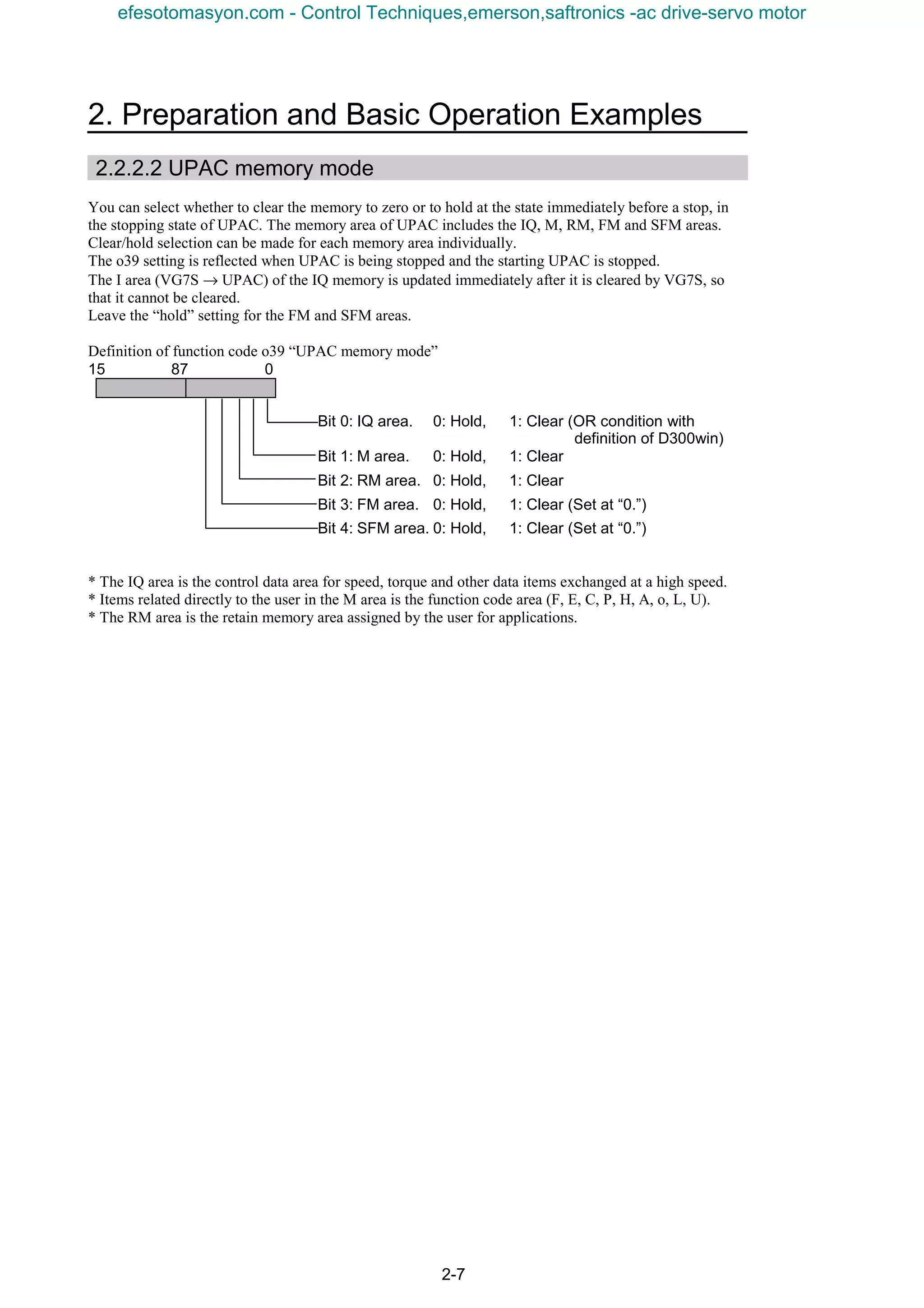
Downloaded 13 times


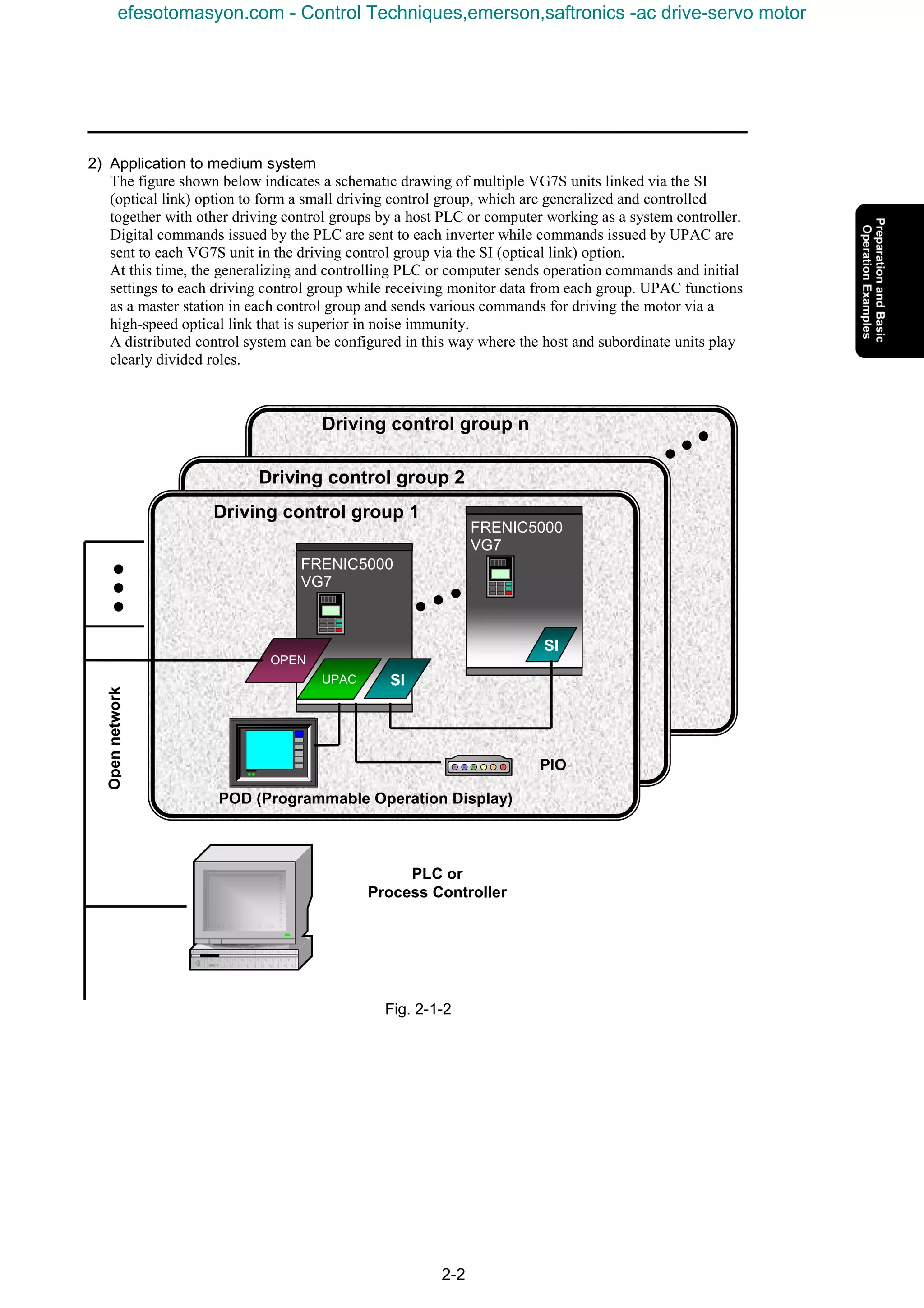
![1-4
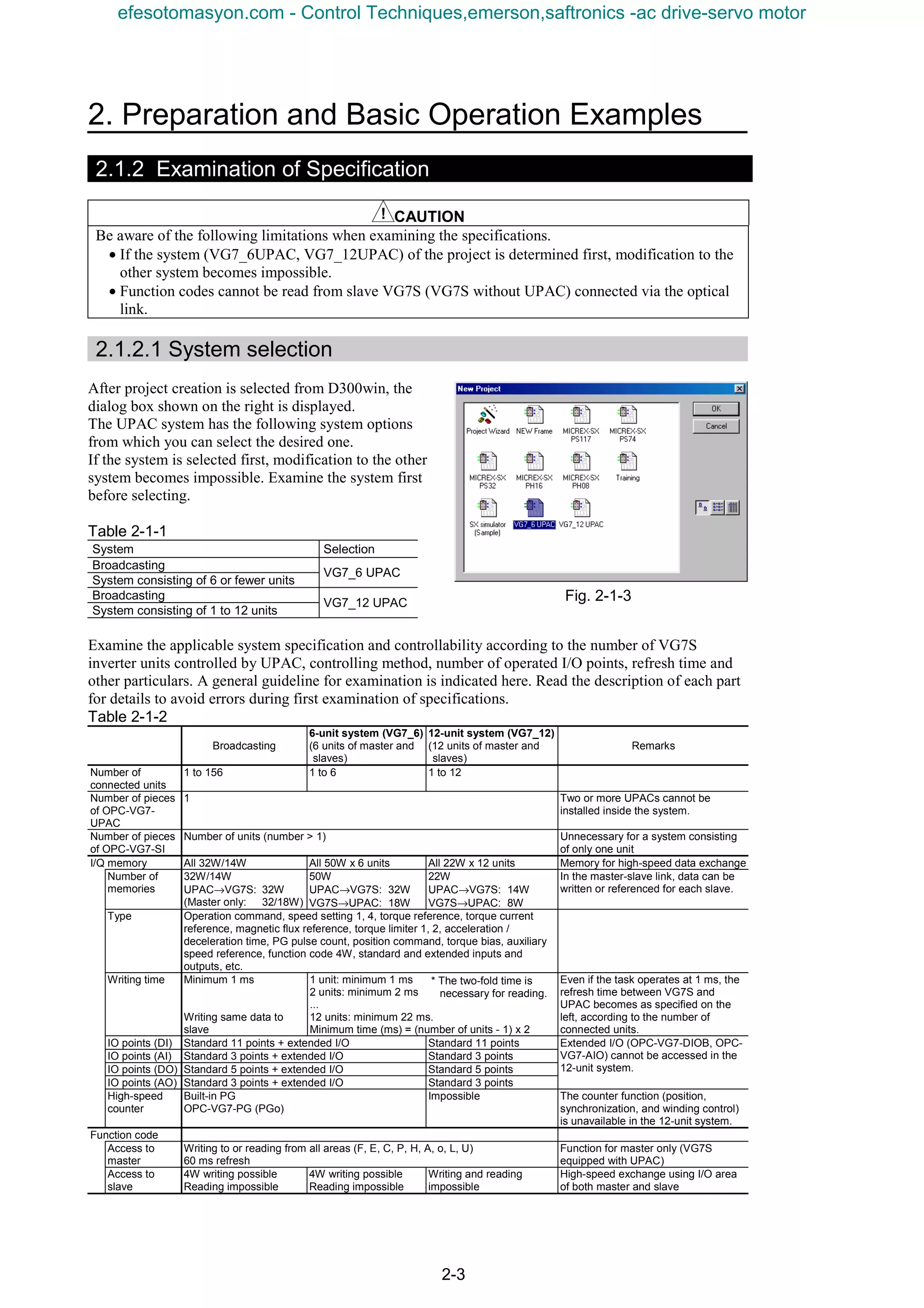
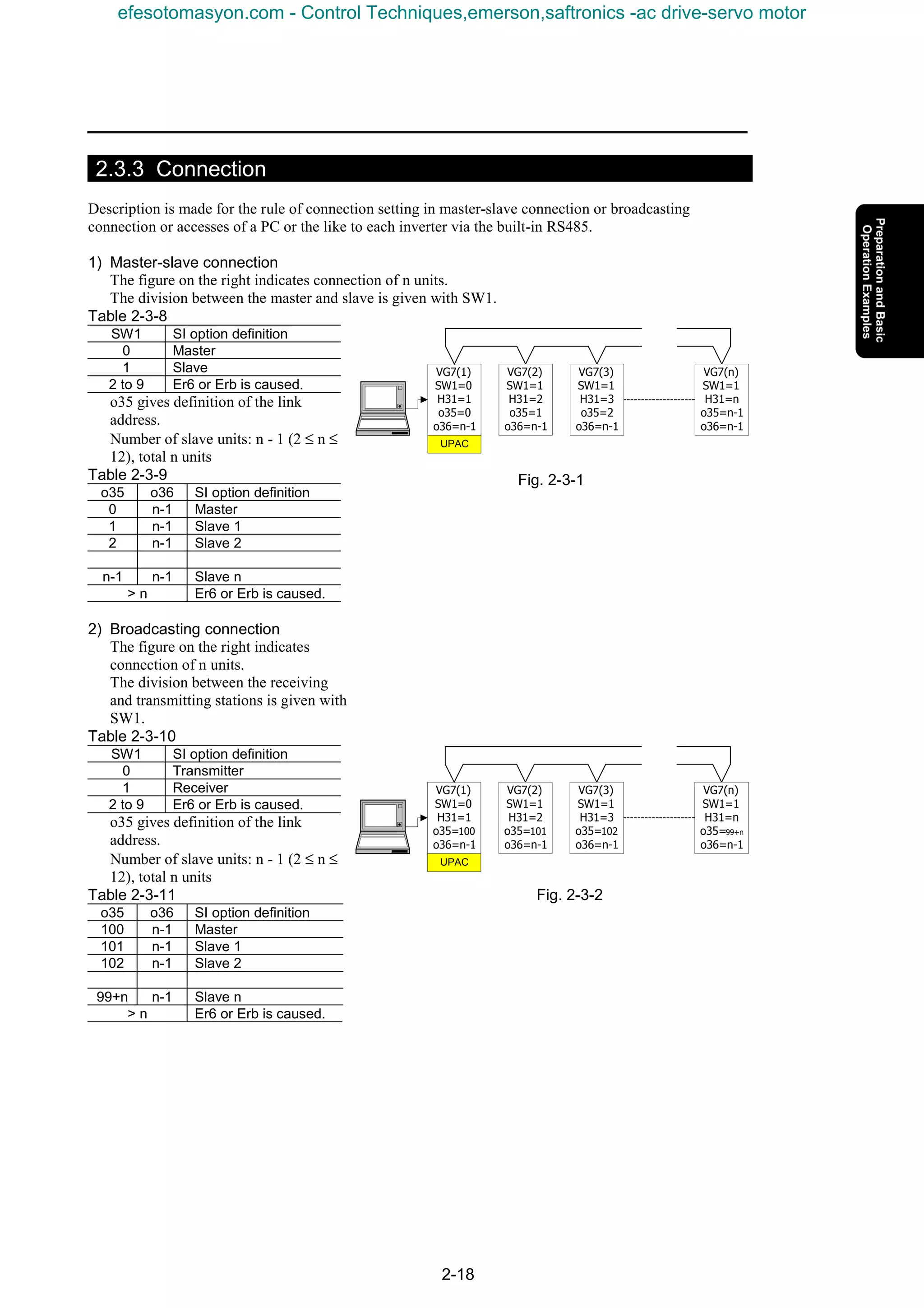
1.2 Preparation of Option
1.2.1 OPC-VG7-UPAC Option
1.2.1.1 Description of product
This card (User Programmable Application Card, UPAC hereafter) is an optional card for the inverter
control installed on FRENIC5000VG7S (VG7S hereafter). This card gives you an additional higher level
control over your inverter. You can also use engineering support tool D300win to facilitate programming
the control applications being used for this card.
UPAC is an optional PLC card integrated into the inverter conforming to MICREX-SX series high
performance CPU module (NP1PS-32). Since UPAC is slightly different in programming specification
such as memory map and available instructions from that for the high performance CPU module, refer to
"5) Programming Specifications" for more information. We recommend you to refer to "MICREX-SX
Series USER’S MANUAL–INSTRUCTIONS" when you design your application program.
n Main features
(1) Application execution function
Executes an application program
Controls tasks for application program (default, fixed period, event)
(2) Support tool interface
RS485 (included in UPAC-VG7S connection bus) 1 channel
(3) RAS functions
Executes self-diagnosis and notifies to the inverter.
(4) Other
Data memory backup with battery
This card enables you to realize controls such as dancer control, tension control, and orientation control
easily.
With inverter link option (OPC-VG7-SI), you can designate an inverter with UPAC installed as a
master and connect up to twelve slave inverters (156 inverters for broadcasting) to control these
individual inverters.
An application program of UPAC runs at minimum execution period of 1ms. The execution period
increases to 2, 3, 4, ... or 32000ms depending on the size of a program.
You can assign up to 64W from static variables used in an application program to the function codes U01
to U64 (user area) of VG7. When you assign parameters for adjustment to this user area, you can use the
KEYPAD panel of VG7 to refer to or change the data without personal computer.
UPAC has some restrictions over SX series high performance CPU module (NP1PS-32). The calendar
function is not available and SX specific instructions are removed. Read this document thoroughly for
complete understanding.
[Limitations]
UPAC is equipped with a high-performance CPU installed in MICREX-SX, but the functions of UPAC
are not fully equivalent. There are limitations in the following functions.
• Calendar and clock function
Because of this, nothing is displayed in the “major failure time information” and “power shutdown
history information” of detail RAS.
The calendar/clock function of D300win always shows “January 01, 1970, 00:00:00.”
• Because UPAC is not equipped with the key switch of MICREX-SX, the key state is always “TERM.”
• HELP of UPAC system definition of D300win is not supported.
• “MICREX-SX” is displayed as the title of each dialog box of D300win.
• Battery change in the live-line state is impossible.
efesotomasyon.com - Control Techniques,emerson,saftronics -ac drive-servo motor](https://image.slidesharecdn.com/vg7upacmanual-140613044924-phpapp01/75/Vg7-upac-manual-16-2048.jpg)
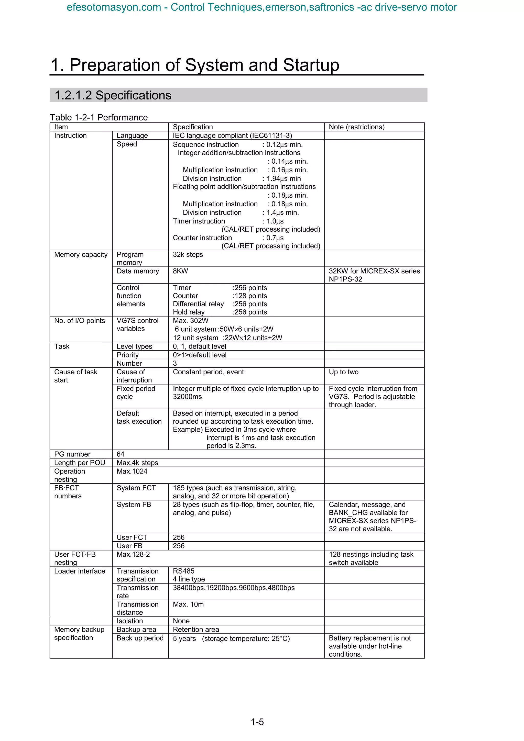
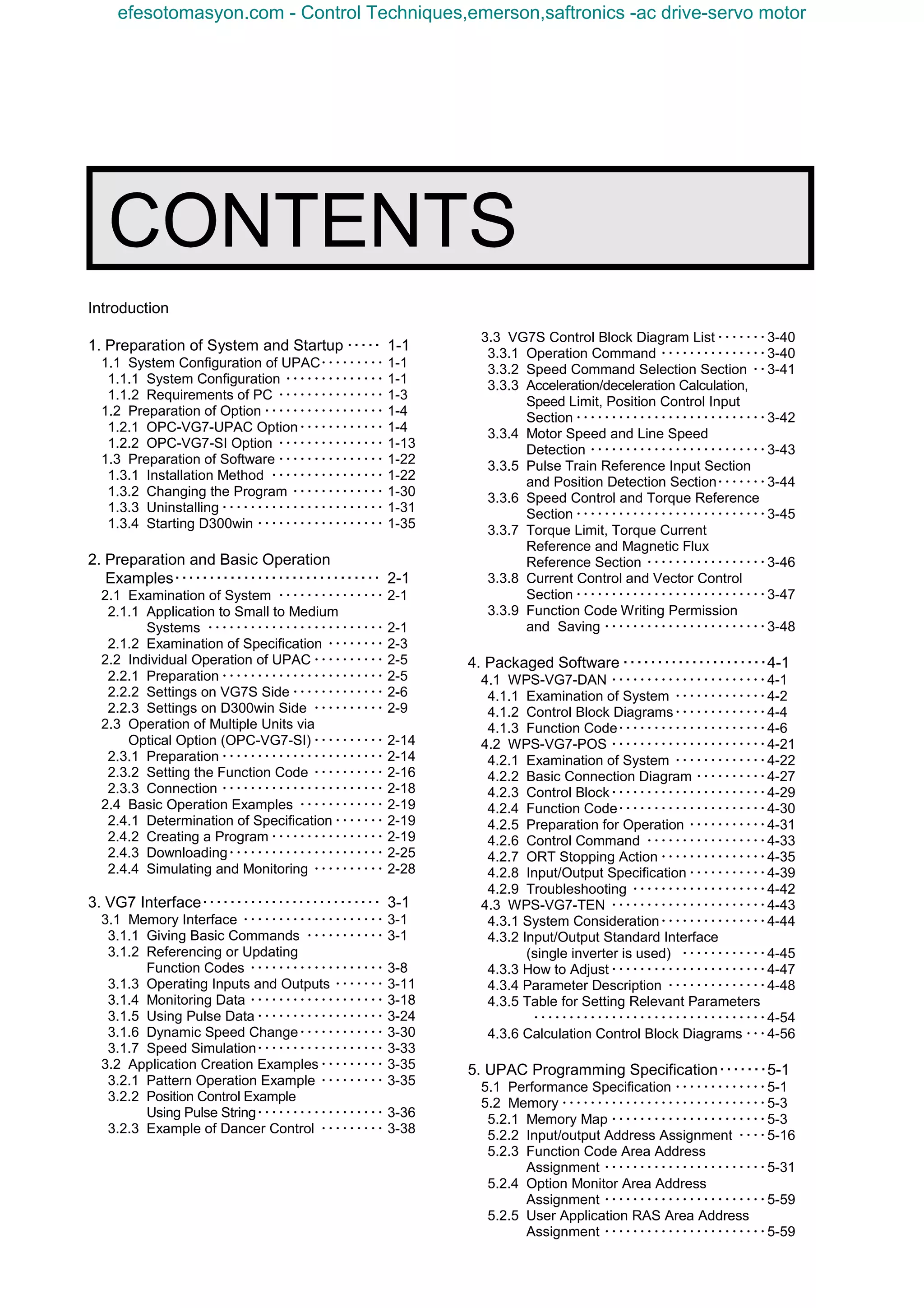
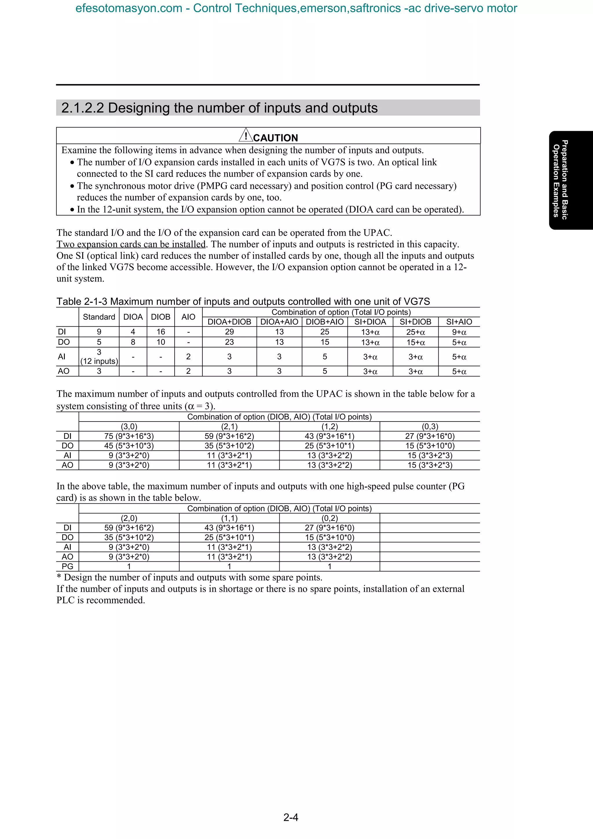
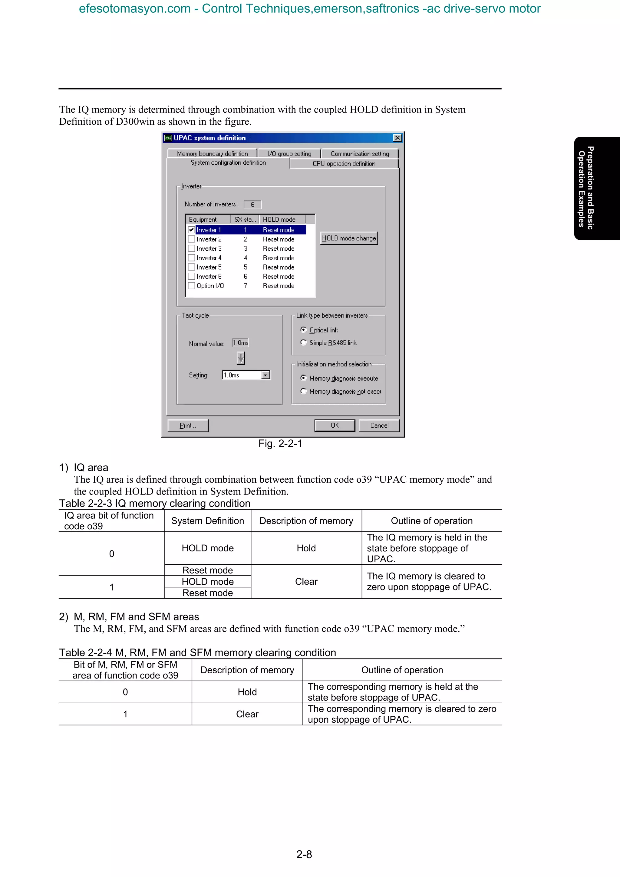
![1. Preparation of System and Startup
1-7
(2) Check for damage given during transportation.
(3) Check if all the accessories are contained.
Accessories: 5 spacers
1 M3 screw
1 backup battery (installed to product)
CAUTION
• Do not operate the product with damaged or missing parts.
Otherwise injuries or material losses may be caused.
1.2.1.4 Operating environment
Operate the option in the same environment as that of the main body of VG7S.
Table 1-2-3 Operating environment
Item Specification
Site Indoors
Ambient
temperature
-10 to +50°C
Relative humidity 5 to 95% (no dew)
Atmosphere Free from dust, direct sunshine, corrosive gases, oil mist, vapor or
water drops.
Little salt inclusion.
No dew or icing caused by abrupt temperature changes.
Altitude 1000 m maximum
Vibration 5.9 m/s2
[0.6 G] maximum
Note: Failure to satisfy the above environmental conditions will cause poor performance, reduced life and failures.
Checkup of ROM version of main body
CAUTION
• Some of options are not compatible with VG7S of early ROM versions. Correct operation is not
ensured with early versions. Be sure to check the ROM version in the maintenance information
given at the keypad panel. If the version is uncertain, contact us.
Check the ROM version of the main body before installing the option.
If the option is already installed, check the ROM version of the main body in the
state.
To check, view the information displayed on the right of “MAIN” and “MTR” in
the maintenance information of the keypad panel.
The screen shown on the right is displayed on page five of the maintenance
information. Press the key of the keypad panel to open page five.
Table 1-2-4
ROM version
Model of option
MAIN MTR
OPC-VG7-UPAC H1003D or later H2003D or later
MAIN=H1xxxx
MTR =H2xxxx
KP =K xxxx
1500
∨∨∨∨
efesotomasyon.com - Control Techniques,emerson,saftronics -ac drive-servo motor](https://image.slidesharecdn.com/vg7upacmanual-140613044924-phpapp01/75/Vg7-upac-manual-19-2048.jpg)
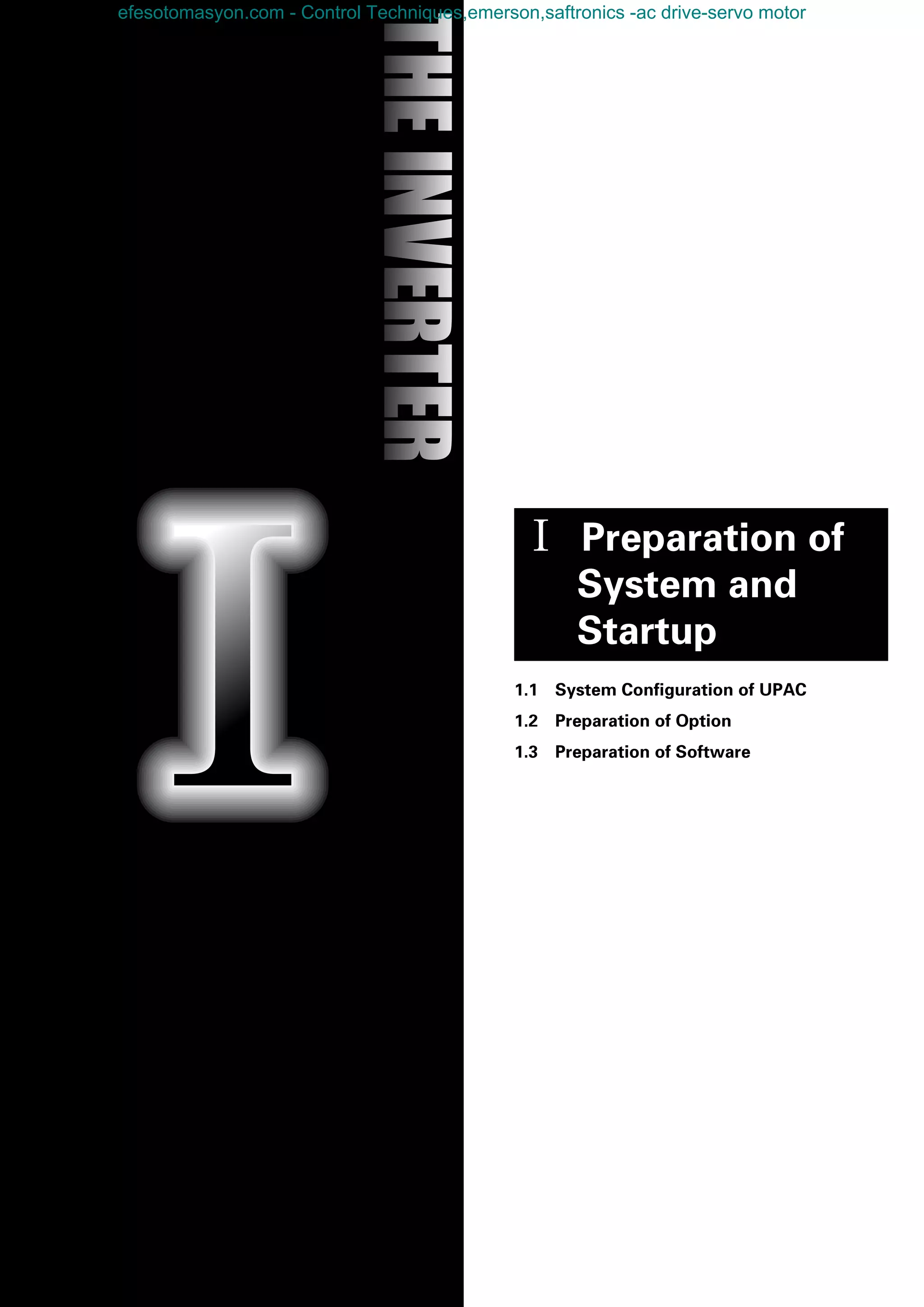
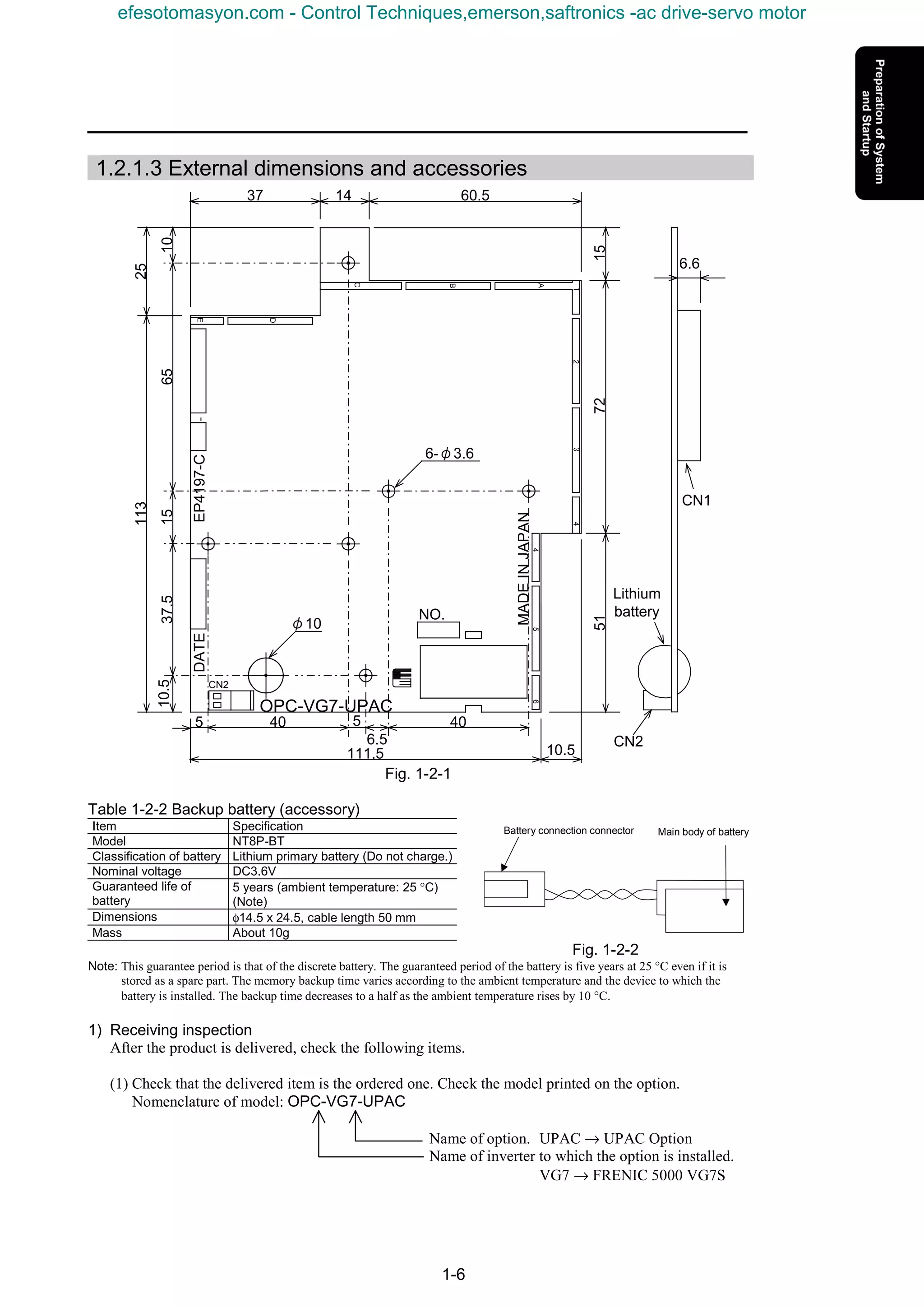
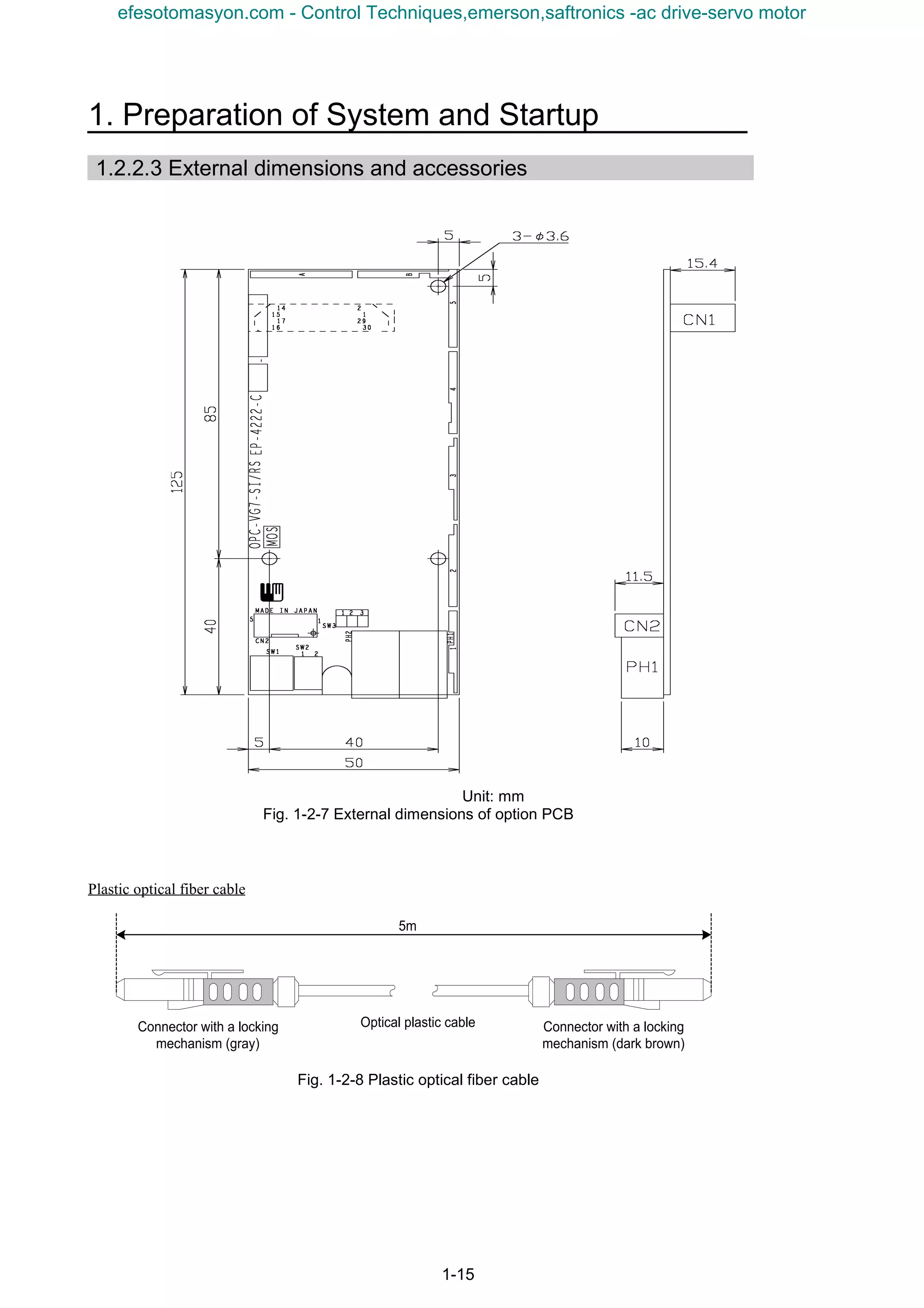
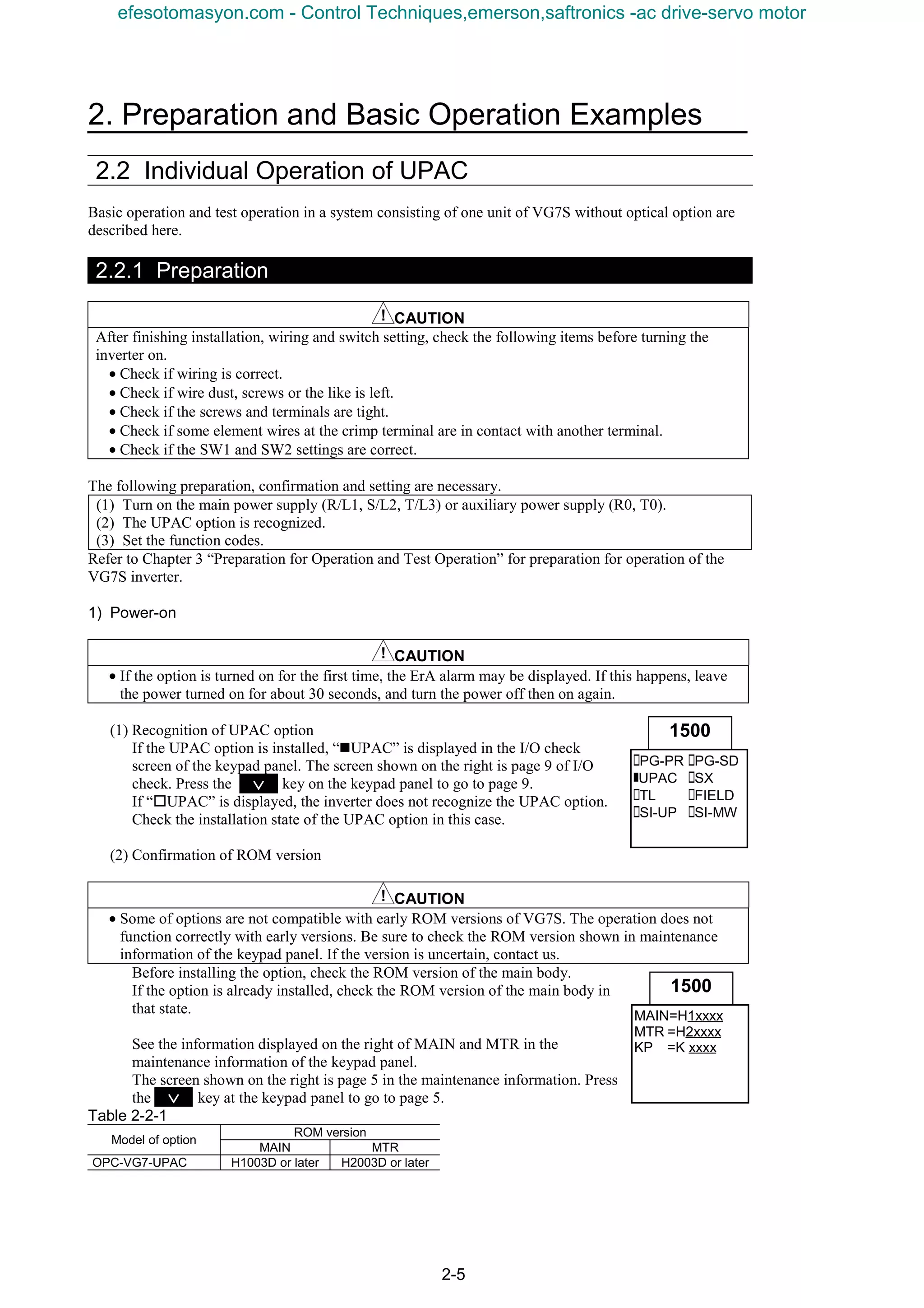
![1-14
* The reading period is
twice the value
written on the left.
1.2.2.2 Specifications
Table 1-2-6 Hardware specifications
Item Specification Remarks
Model OPC-VG7-SI
Optical option
(High-speed serial link)
Connector Transmission (TX) / reception (RX) connector
Definition
Define “SI (UPAC)” using SW 1 and SW 2 on the option.
(SW1, SW2) = (ON, OFF)
Power supply The power is supplied through the connector.
Accessory Plastic optical fiber cable (5 m)
Communication specifications
Item Specification Remarks
Connection style Loop-back connection through plastic optical fiber cable
Communication
speed
4Mbps
Communication
distance
Max. extension distance: 20 m (distance between adjacent inverters)
For systems exceeding 20 m, contact us.
The accessory cable attached to
the product is 5 m long.
Connection
method
Master-slave method (Max. 12 units)
Broadcasting method (Max. 156 units)
Selection with function code
Number of
connected
inverters
Master-slave method
6-unit system: Max. 6 units (50 W inputs/outputs per unit)
12-unit system: Max. 12 units (22W inputs/outputs per unit)
Broadcasting method
Max. 156 units (32 W outputs per unit)
Selection in D300win screen.
The “broadcasting method”
indicates the function where the
same data is written from the
master to all inverters.
Writing time
Master-slave method
Time = (n-1) x 2 (ms)
(n: n > 1; number of units)
2 units: 2 ms
3 units: 4 ms
4 units: 6 ms
5 units: 8 ms
6 units: 10 ms
7 units: 12 ms
8 units: 14 ms
9 units: 16 ms
10 units: 18 ms
11 units: 20 ms
12 units: 22 ms
Broadcasting method:
1 ms
Communication
link
establishment
confirmation
Blinking green LED on option
The digital output indicates the communication state.
The lamp blinking at 500 ms
interval indicates establishment
of the communication link.
[0-D07] is used: “1” indicates
establishment of the
communication link.
Protective
function
Inverter being stopped;
The protective function does not work if the communication link is not
established.
Inverter running;
Protective function “inverter-to-inverter link error” is developed if the
communication link is not established.
The conditions for failure of
establishment of the
communication link are:
- Illegal setting (function code,
System Definition)
- Broken wire in communication
link (broken wire, bending at 35
mm or a smaller curvature, etc.)
Fail-soft
operation
The option is not compatible with degeneracy operation.
→ When inverters are connected via optical link in a system consisting of
total n units (2 ≤ n ≤ 156: n is an integer), the communication link is lost if
x (1 ≤ x ≤ n-1: x is an integer) units of inverters are turned off. Turn on all
n units of inverters (or control power of the inverters).
Software specifications
Item Specification Remarks
ROM version
H10060 or later, H20060 or later
Operate at the above ROM versions. (Use the I/O check at the keypad
panel to check the ROM version).
Definition of
connection
- Master-slave function code o35, o36
- o36 set only at master
If these settings are wrong, the
communication link is not
established.
Input/output data
Master-slave method
I/Q area; selection between 50W and 22W
Function code area;
All codes can be read or written only at the master inverter (equipped
with UPAC). Only the 4W function code data can be written at the slave
inverter.
Broadcasting method
Q area only; 32W (Only the master can refer to 18W in the I area.)
Selected in 6-/12-unit system
With the broadcasting method,
only the output selection of
inverter 1 of a 6-unit system can
be used.
efesotomasyon.com - Control Techniques,emerson,saftronics -ac drive-servo motor](https://image.slidesharecdn.com/vg7upacmanual-140613044924-phpapp01/75/Vg7-upac-manual-26-2048.jpg)
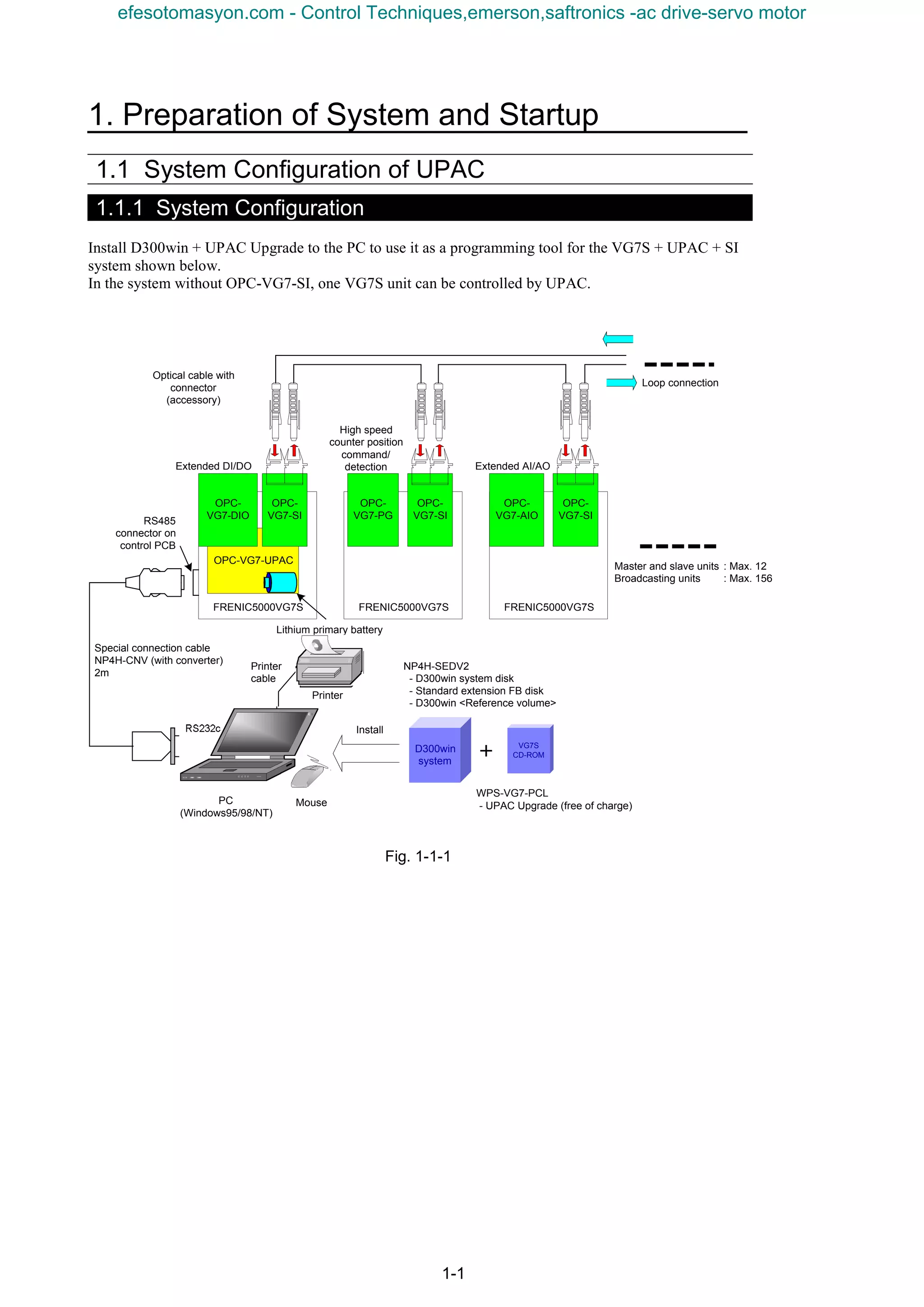
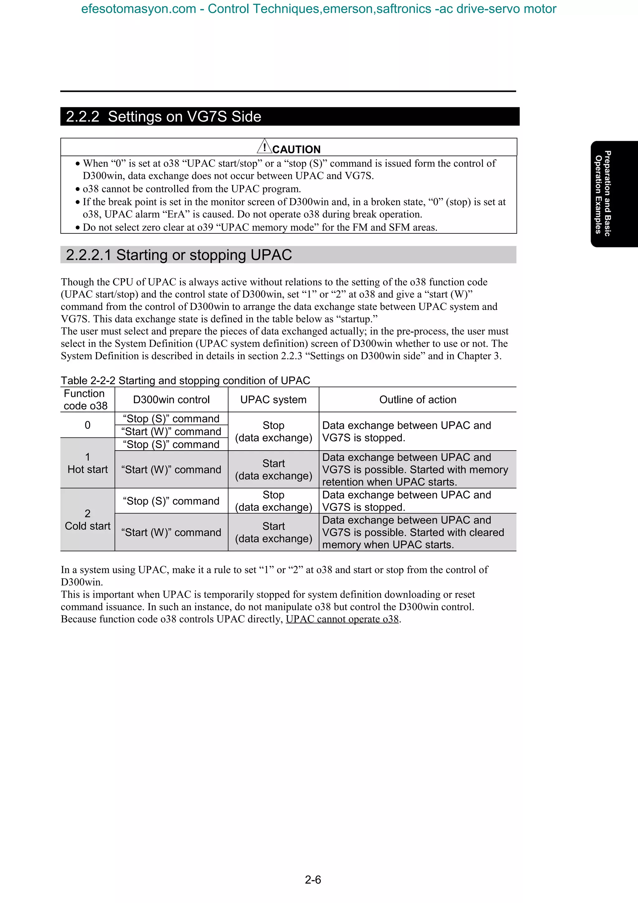
![1-16
1) Receiving inspection
When the product is delivered, check the following items.
(1) Check if the product is what you have ordered. Check the model printed on the option.
Nomenclature of model: OPC-VG7-SI
Name of option SI → Optical ink option
(Abbreviation of Serial Interface)
Name of inverter to which VG7 → FRENIC5000VG7S
the option is installed
(2) Check if the product is damaged during transportation.
(3) Check that all the accessories are included.
3 spacers
3 screws (M3)
1 plastic optical fiber cable (for transmission and reception)
CAUTION
• Do not use the option with damaged or missing parts.
• Otherwise injuries or material losses may be caused.
1.2.2.4 Operating environment
Use the option in the same environment as that of the VG7S main body.
Table 1-2-7 Operating environment
Item Specification
Site Indoors
Ambient temperature -10 to +50°C
Relative humidity 5 to 95% (no dew)
Atmosphere
Free from dust, direct sunshine, corrosive gases, oil mist, vapor or water drops.
Little salt inclusion.
No dew or icing caused by abrupt temperature changes.
Altitude 1000 m maximum
Vibration 5.9 m/s2
[0.6 G] maximum
Note: Failure to satisfy the above environmental conditions will cause poor performance, reduced life and failures.
Checkup of ROM version of main body
CAUTION
• Some of options are not compatible with VG7S of early ROM versions. Correct operation is not
ensured with early versions. Be sure to check the ROM version in the maintenance information
given at the keypad panel. If the version is uncertain, contact us.
Check the ROM version of the main body before installing the option.
If the option is already installed, check the ROM version of the main body in the
state.
Check the ROM version of the main body of VG7 (not optical option or keypad
panel).
To check, view the information displayed on the right of “MAIN” and “MTR” in
the maintenance information of the keypad panel.
The screen shown on the right is displayed on page five of the maintenance information. Press the
key of the keypad panel to open page five.
MAIN=H1xxxx
MTR =H2xxxx
KP =K xxxx
1500
∨∨∨∨
efesotomasyon.com - Control Techniques,emerson,saftronics -ac drive-servo motor](https://image.slidesharecdn.com/vg7upacmanual-140613044924-phpapp01/75/Vg7-upac-manual-28-2048.jpg)
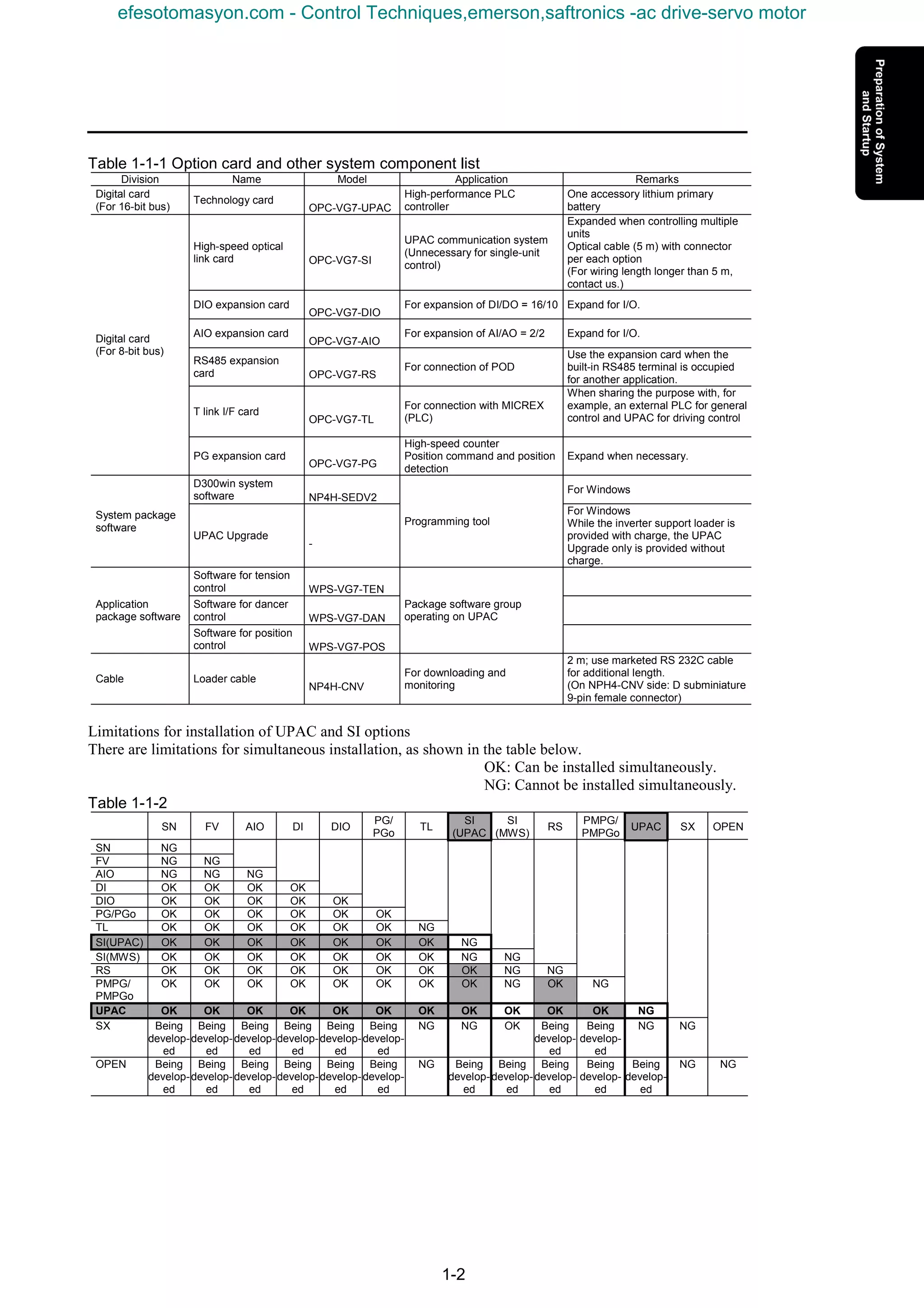
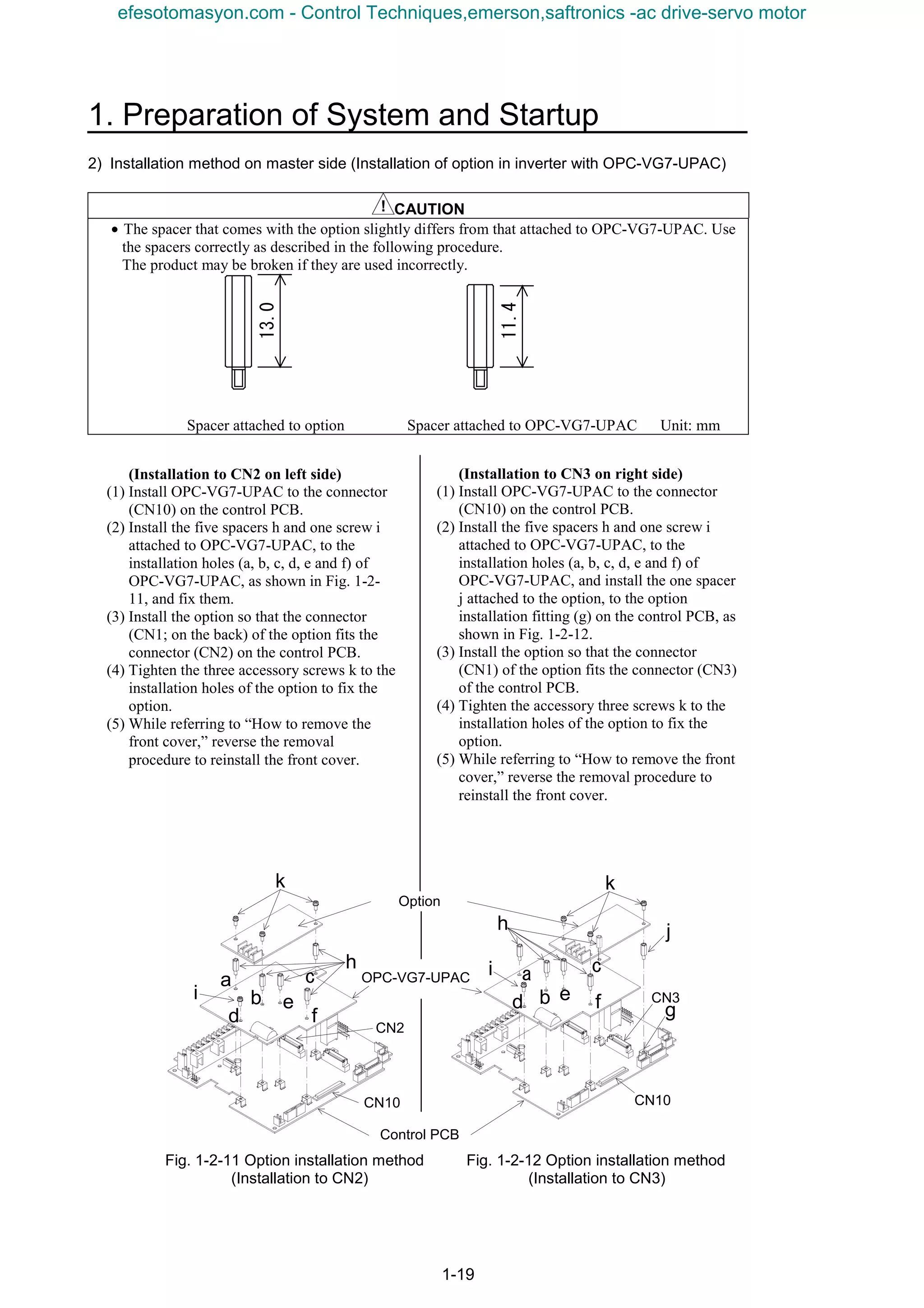
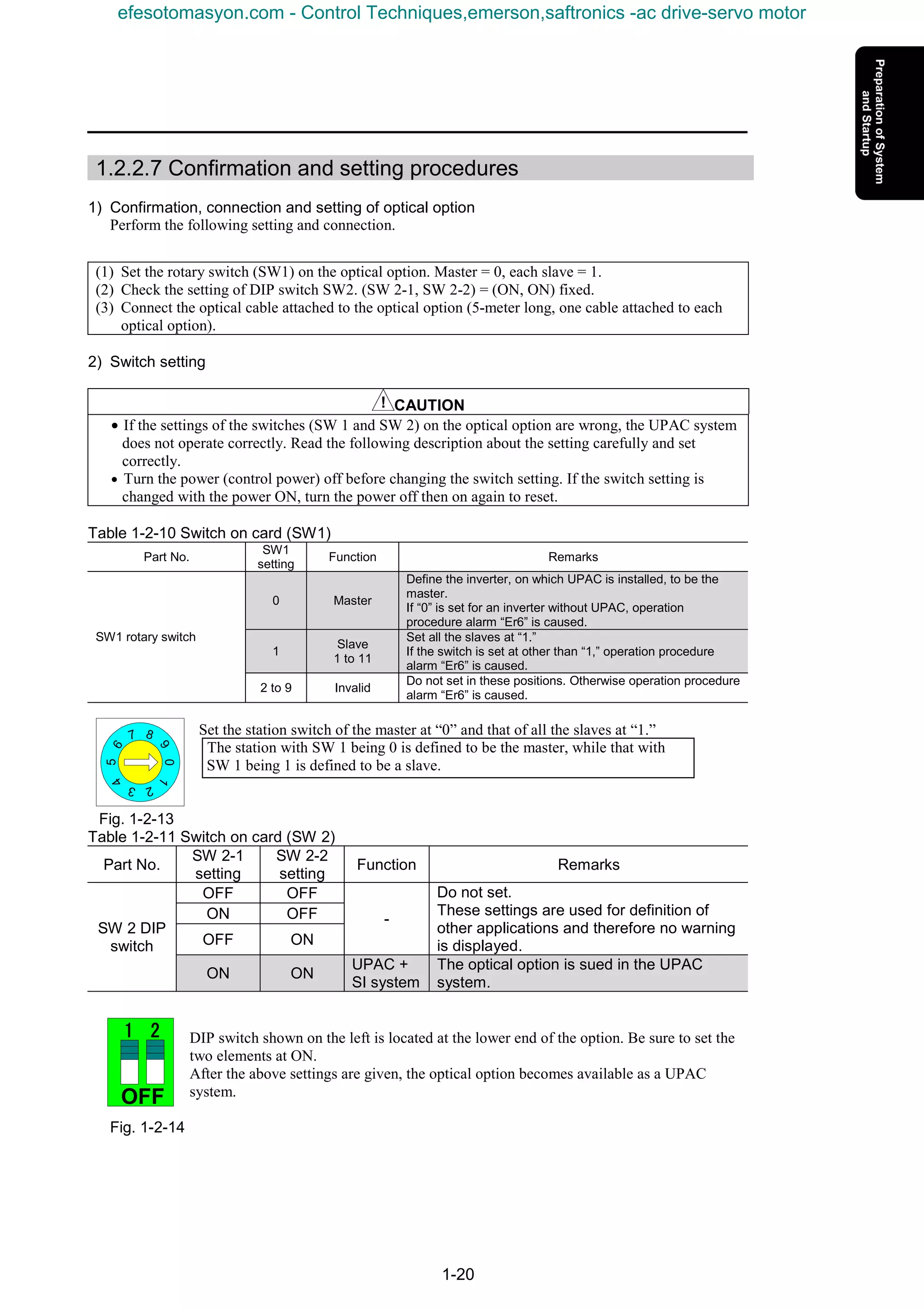
![1-18
1.2.2.6 Installation method
CAUTION
• The product may be broken due to inadequate work during installation or removal.
• Before installing or removing the option, turn the inverter off and check that the CHARGE lamp is
unlit. Even if all the main circuit, control and auxiliary power supply of the inverter are turned off,
control terminals 30A, 30B, 30C, Y5A and Y5C of the inverter are live when the external control
circuit is powered by another power supply.
• Turn the external power supply off to avoid electric shock.
There are the following limitations in installation of the option.
K If the option is for a slave unit in an inverter without OPC-VG7-UPAC, refer to [1) Installation
method on slave side] to install on either installation position (CN2 on the left side or CN3 on the
right side) on the control PCB. However, when the analog option is installed, too, be sure to install the
option on the CN2 side and install the analog option on the CN3 side.
K If the option is for a master unit in an inverter with OPC-VG7-UPAC, refer to [2) Installation method
on master side] to install on either installation position (CN2 on the left side or CN3 on the right side)
on the control PCB.
1) Installation method on slave side
(For slave unit in inverter with OPC-VG7-UPAC)
Fig. 1-2-9 Option installation method Fig. 1-2-10 Option installation method
(Installation to CN2) (Installation to CN3)
(Installation to CN3 on right side)
(1) Install the three accessory spacers g to
the option installation fittings (d, e and
f) on the control PCB.
(2) Install the option so that the connector
(CN1; on the back) of the option fits the
connector (CN3) on the control PCB.
(3) Tighten the three accessory screws h in
the installation holes of the option to fix
the option.
(4) While referring to “How to remove the
front cover,” reverse the removal
procedure to reinstall the front cover.
(Installation to CN2 on left side)
(1) Install the three accessory spacers g to the
option installation fittings (a, b and c) on the
control PCB.
(2) Install the option so that the connector
(CN1; on the back) of the option fits the
connector (CN2) on the control PCB.
(3) Tighten the three accessory screws h in the
installation holes of the option to fix the
option.
(4) While referring to “How to remove the front
cover,” reverse the removal procedure to
reinstall the front cover.
Control PCB
Option
a
b c
g
h
d
e
f
g
h
CN2
CN3
efesotomasyon.com - Control Techniques,emerson,saftronics -ac drive-servo motor](https://image.slidesharecdn.com/vg7upacmanual-140613044924-phpapp01/75/Vg7-upac-manual-30-2048.jpg)
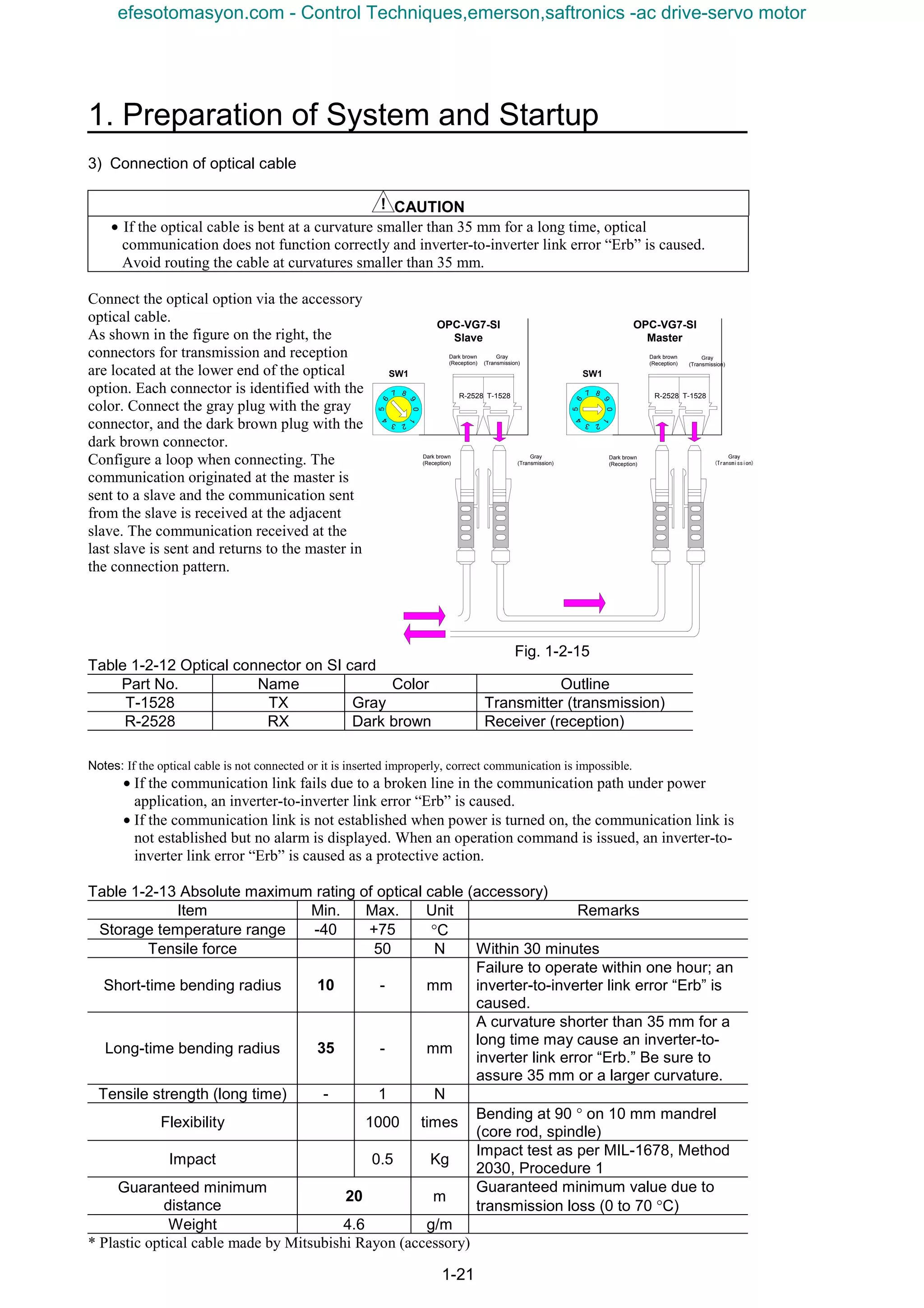
![1-22
1.3 Preparation of Software
1.3.1 Installation Method
1.3.1.1 Installing the D300win software package
The D300win software package is delivered in multiple floppy disks. Installation disks contain an install
program which automatically proceeds necessary actions for installation, icon registration and so on.
When installation is made via a network, copying or installation may not proceed correctly according
to some network environment and operating environment.
(1) Inactivate the virus detection software and screen saver.
(2) Select [Control Panel (C) ...] from the [Settings (S) ...] submenu in the [Start] menu of Windows
95/98/NT4.0. (The case of Windows 98 is described in the following description as a typical
example.)
(3) Double-click the left mouse button on the “Add/Remove Programs” icon in the “Control Panel” dialog
box.
(4) Click the left mouse button on the [Install (I) ...] button.
(5) Insert the System Disk No. 1 containing the install program into the floppy disk drive.
(6) Click the left mouse button on the [Next (N) >] button.
(7) Check that <A:Setup.exe> is displayed in the [Command line (C) of install program:] text box. If not,
click the left mouse button on the [Browse (R) ...] button, select the drive in which the floppy disk is
inserted, and select [Setup.exe] as a file name. Click the left mouse button on the [Finish (F)] button.
(8) A dialog box showing information for installation and program handling is displayed.
Click the left mouse button on the [Next (N)>] button.
The [Choose Folder] dialog box is displayed.
(9) To change the default destination folder “C:D300win,” click the left mouse button on the [Browse
(R) ...] button, designate the desired folder in the [Choose Folder] dialog box, and click the left mouse
button on the [OK] button.
Fig. 1-3-1
Designate the folder name and path
within eight characters. Do not use
space.
efesotomasyon.com - Control Techniques,emerson,saftronics -ac drive-servo motor](https://image.slidesharecdn.com/vg7upacmanual-140613044924-phpapp01/75/Vg7-upac-manual-34-2048.jpg)
![1. Preparation of System and Startup
1-23
(10) Click the left mouse button on the [Next (N)>] button further.
The “Setup Type” dialog box is displayed.
Fig. 1-3-2
Select the [Typical (T)], [Compact (C)] or [Custom (U)] method for setup, then click the left mouse
button on the [Next (N)>] button.
1) If custom installation is selected
If [Custom] is selected, the “Select Components” dialog box is displayed.
Place a check box for the desired installation items.
Fig. 1-3-3
Click on the [Next (N)>] button.
efesotomasyon.com - Control Techniques,emerson,saftronics -ac drive-servo motor](https://image.slidesharecdn.com/vg7upacmanual-140613044924-phpapp01/75/Vg7-upac-manual-35-2048.jpg)
![1-24
2) Description of selection items
• D300win program
Basic program of D300win. Be sure to select to install.
• MICREX-SX
Select to create programs for MICREX-SX Series.
• SX simulator (Sample)
Select to simulate MICREX-SX Series program on the PC (D300win). This function is being
developed and provided as a sample.
• Page Layout
Select to use five page layout samples necessary for printing a project, worksheet or the like.
(The introduced page layout file (DEFAULT.plt) is installed without fail.)
• POD cooperated support
Function for establishing association in variable allocation and so on in a system of our POD
(programmable operation display) UG210/UG400 series and MICREX-SX series
• Import & Export of variable name
Function for inputting or outputting variable names from/to a CSV file (text file)
• Easy operation menu
Basic operations of D300win are selected from a menu (selection of purpose) to execute
operations ranging from project creation to debugging.
(11) The “Select program folder” dialog box is displayed. To change default “D300win,” enter the
desired program folder name in the text box.
Click the left mouse button on the [Next (N)>] button.
(12) The “Start file copy” dialog box is displayed. Confirm the description and click the left mouse
button on the [Next (N)>] button.
Files are copied.
(13) After installation with the first system disk is finished, an “Setup Needs The Next Disk” dialog box
is displayed as shown in the figure below.
Insert the second disk and click the left mouse button on the [OK] button. Similarly install the third
and the remaining disks.
Fig. 1-3-4
efesotomasyon.com - Control Techniques,emerson,saftronics -ac drive-servo motor](https://image.slidesharecdn.com/vg7upacmanual-140613044924-phpapp01/75/Vg7-upac-manual-36-2048.jpg)
![1. Preparation of System and Startup
1-25
(14) After all disks are installed, an “Question” dialog box shown below is displayed.
Fig. 1-3-5
Click the left mouse button on the “No (N)” button.
If the left mouse button is clicked on the [Yes (Y)] button, the “Backup utility” dialog box is
displayed and you can back up the project files created using “Ver 1.*” D300win system.
(15) If [SX simulator] has been selected using “Custom” installation, the following message box is
displayed after all system disks are installed.
Fig. 1-3-6
(16) After setup is completed, the following screen is displayed.
Fig. 1-3-7
(17) After confirming that there is no problem even if the computer is restarted, select the [Yes, I want to
restart my computer now.] option button and click the left mouse button on the [Finish] button. The
computer restarts itself to complete setup of D300win.
Select this option button
and click the left mouse
button on the [Finish]
button. The PC starts again.
efesotomasyon.com - Control Techniques,emerson,saftronics -ac drive-servo motor](https://image.slidesharecdn.com/vg7upacmanual-140613044924-phpapp01/75/Vg7-upac-manual-37-2048.jpg)
![1-26
1.3.1.2 Installing UPAC support function
Use an installation program to install.
The installation program executes the following process.
• Adds the UPAC support function to D300win.
• Adds an uninstall icon for the UPAC support function to the program folder.
1) Before installing
CAUTION
• Before installing the UPAC support function, you need to install D300win. Install D300win first if
you have not installed D300win. See " MICREX - SX Series USER’S MANUAL D300win
<GUIDE>" for installing D300win.
If you have installed the UPAC support function, uninstall the UPAC support function for safety.
Though you can overwrite to install without uninstalling, you will have such a problem as you cannot
uninstall the UPAC support function completely. When you upgrade the version, we recommend that
you uninstall first and then install again.
2) Installing
This process adds the UPAC support function to installed D300win. Follow the procedure below.
(1) Stop your virus detection software and screen saver.
(2) Click the [Start] button, point to [Settings (S)], and then click [Control Panel (C)] of Windows.
(3) Click the [Add/Remove Programs] icon in the Control Panel window.
(4) Click the [Install (I)] button.
(5) Insert a recording media (CD-ROM, WPS-VG7-PCL) containing the installation program into the
drive.
(6) Click the [Next (N)>] button.
(7) Check if "A:SETUP.EXE" is displayed in the text box of Command line for installation program
(C): ("A:" depends on the recording device you are using). Otherwise, click the [Browse (R)…]
button to specify the drive and the folder.
(8) Left-click the [Finish] button.
Note: • The menu names and the dialog box names in step (2) to (7) depend on the OS you are using. Substitute them if needed.
• You can use Explorer to left-double click the SETUP.EXE in the recording media containing the installation program
instead of executing the operation from (2) to (7).
efesotomasyon.com - Control Techniques,emerson,saftronics -ac drive-servo motor](https://image.slidesharecdn.com/vg7upacmanual-140613044924-phpapp01/75/Vg7-upac-manual-38-2048.jpg)
![1. Preparation of System and Startup
1-27
(9) A while after [InstallShield Wizard]
working box is displayed, a dialog box
showing the information on installation
and how to handle this program appears.
Click the [Next (N) >] button after you
are satisfied.
Fig. 1-3-8
(10) If an already installed UPAC support
function is found, a dialog box for
modifying, editing or deleting the
program is displayed. Select [Repair
(E) ] and click on the [Next (N) >]
button to install again. Settings in
steps 11 through 14 cannot be given in
this case.
Fig. 1-3-9
(11) A dialog box for choosing Destination
Location appears.
The Destination Folder contains the
directory where D300win is installed
(if D300win is not found, "C:
D300win" is displayed).
Confirm the destination directory and
left-click the [Next (N) >].
Fig. 1-3-10
efesotomasyon.com - Control Techniques,emerson,saftronics -ac drive-servo motor](https://image.slidesharecdn.com/vg7upacmanual-140613044924-phpapp01/75/Vg7-upac-manual-39-2048.jpg)
![1-28
“Choose Folder” dialog box appears.
If you want to change this folder, click the [Brouse
(R)… ] button in the Choose Destination Location dialog
box, and specify another folder where D300win is
installed, and click [OK].
Fig. 1-3-11
The left message box appears when D300win was not
found in the folder you specified.
Left-click the [OK] button to close the message and
specify the folder again.
Fig. 1-3-12
(12) The “Select Components” dialog box is
displayed.
Select the desired components to be
installed, and click the left mouse button
on the [Next (N)>] button.
Fig. 1-3-13
(13) The “Select Program Folder” dialog box
appears.
If you change the default D300win
folder, enter the program folder name in
the text box.
Note: Though you can specify a folder other than the
folder where D300win is installed, the same folder
is convenient for uninstalling.
Fig. 1-3-14
efesotomasyon.com - Control Techniques,emerson,saftronics -ac drive-servo motor](https://image.slidesharecdn.com/vg7upacmanual-140613044924-phpapp01/75/Vg7-upac-manual-40-2048.jpg)
![1. Preparation of System and Startup
1-29
(14) Click the [Next (N) >] button. The
“Start Copying Files” dialog box
appears.
Confirm the installation setting and
click the [Next (N) >] button.
Fig. 1-3-15
(15) Files are copied and the icon is
registered to the Program folder.
You can click the [Cancel] button to
pause the operation to select to retry
or to stop during the installation.
Fig. 1-3-16
Before you click the [Next (N) >] button in the Start Copying Files dialog box, you can click the
[<Back (B)] button to return to the previous dialog box and change the setting.
(16) When the setup has been completed,
the dialog box on the left appears.
Click the [Finish] button to restart
the computer.
Fig. 1-3-17
efesotomasyon.com - Control Techniques,emerson,saftronics -ac drive-servo motor](https://image.slidesharecdn.com/vg7upacmanual-140613044924-phpapp01/75/Vg7-upac-manual-41-2048.jpg)
![1-30
1.3.2 Changing the Program
Option programs can be added or deleted to/from the D300win system having been installed, or the
program having been set up can be installed again.
(1) Click the left mouse button on the [Start] button of the Windows system and select [D300win]
program group from the [Programs (P)] menu, then click the left mouse button on the [D300win
setup] program icon.
* Click the left mouse button on the [UPAC setup] program icon to add,
delete or reinstall the UPAC support function program in the same
procedure as shown.
Fig. 1-3-18
(2) The dialog box for modifying, repairing or removing the program is displayed.
Fig. 1-3-19
(3) Select the [Modify (M)] option button and click the left mouse button on the [Next (N)>] button.
The “Select components” dialog box is displayed.
Fig. 1-3-20
(4) Place a check mark for component list items to be added, and clear the check box for those to be
removed, and click the left mouse button on the [Next (N)>] button.
(5) If additional components are marked, a [Change disk] dialog box is displayed. Insert the prompted
disk and click the left mouse button on the [Next (N)>] button.
(6) After installation is completed, the [Maintenance Complete] dialog box shown in the next subsection
is displayed.
Click the left mouse button on the [Finish] button to close the dialog box.
efesotomasyon.com - Control Techniques,emerson,saftronics -ac drive-servo motor](https://image.slidesharecdn.com/vg7upacmanual-140613044924-phpapp01/75/Vg7-upac-manual-42-2048.jpg)
![1. Preparation of System and Startup
1-31
1.3.3 Uninstalling
1.3.3.1 Uninstalling the UPAC support function
To delete the UPAC support function from the hard disk, follow the procedure below.
(1) After selecting the [D300win] program folder from the [Programs (P) ...] submenu in the [Start] menu
of Windows, click on the [UPAC setup] (use the program folder having been designated during
installation).
Fig. 1-3-21
(2) A dialog box for modifying, repairing or removing the program is displayed.
Select [Remove (R)] and click on the
[Next (N)>] button.
Fig. 1-3-22
(3) The “Confirm File Deletion” message box is displayed.
To proceed, click on the
[OK] button. Deletion is
executed.
Fig. 1-3-23
(4) The following dialog box is displayed during deletion.
Fig. 1-3-24
efesotomasyon.com - Control Techniques,emerson,saftronics -ac drive-servo motor](https://image.slidesharecdn.com/vg7upacmanual-140613044924-phpapp01/75/Vg7-upac-manual-43-2048.jpg)
![1-32
(5) Finish the procedure.
Click on the [Finish] button to
close the dialog box.
Fig. 1-3-25
Reference
• Files created and saved by the user are not deleted during program deletion.
• If D300win is uninstalled without uninstalling the UPAC support function, file deletion does not
function correctly. Uninstall the UPAC support function before uninstalling D300win.
• You can uninstall similarly, using [Add/Remove Programs] in the “Control Panel” window.
efesotomasyon.com - Control Techniques,emerson,saftronics -ac drive-servo motor](https://image.slidesharecdn.com/vg7upacmanual-140613044924-phpapp01/75/Vg7-upac-manual-44-2048.jpg)
![1. Preparation of System and Startup
1-33
1.3.3.2 Uninstalling D300win
To delete the D300win system file from the hard disk, follow the procedure below.
(1) Click on the [Start] button of the Windows system and select the [D300win] program group from the
[Programs (P)] menu, and click the left mouse button on the [D300win setup] program icon.
Fig. 1-3-26
(2) A dialog box for modifying, repairing or removing the program is displayed.
Fig. 1-3-27
(3) Select the [Remove (R)] option button and click the left mouse button on the [Next (N)>] button.
The “Confirm File Deletion” message box is displayed.
Fig. 1-3-28
To proceed, click the left mouse button on the [OK] button.
(4) Deletion is executed.
A “Shared File Detected” dialog box may be displayed during operation. Deletion of a shared file may
cause another program to fail to function or Windows may not start in the worst case. Select [No (N)]
usually.
Fig. 1-3-29
efesotomasyon.com - Control Techniques,emerson,saftronics -ac drive-servo motor](https://image.slidesharecdn.com/vg7upacmanual-140613044924-phpapp01/75/Vg7-upac-manual-45-2048.jpg)
![1-34
Finish the procedure.
Fig. 1-3-30
(5) Click the left mouse button on the [Finish] button to close the [Setup] dialog box.
Files created and saved by the user are not deleted during program deletion.
efesotomasyon.com - Control Techniques,emerson,saftronics -ac drive-servo motor](https://image.slidesharecdn.com/vg7upacmanual-140613044924-phpapp01/75/Vg7-upac-manual-46-2048.jpg)
![1. Preparation of System and Startup
1-35
1.3.4 Starting D300win
1.3.4.1 D300win starting method
There are the following two methods to start D300win. Do not start D300win in other methods.
1) Start from the [Start] menu
After the D300win system is installed, a new program group having the icon shown below is created.
The program group is registered to the [Start] menu.
Fig. 1-3-31
* Click the left mouse button on the [Start] button, select the [D300win] program group from the
[Programs (P)] menu, and click the left mouse button on the [D300win] program icon.
After the D300win system starts, the screen shown in section 1.3.4.2 is displayed.
<Description of icon in program group>
The [D300win] icon is the icon for starting the D300win system.
The [SX Control Utility] icon is the icon for starting the SX control utility of the
MICREX-SX Series. Using the SX control utility, the input/output data of the basic
input/output module on the MICREX-SX system can be monitored and outputs can
be checked.
The [File Divide & Merge] icon is the icon for starting the file divide & merge
function. Use the file divide & merge function to divide and save one compressed
project file (file larger than floppy disk capacity) or join the separate files into one.
The [Backup Utility] icon starts the program for backing the project file created
using an earlier version of D300win. (The project file created with Ver 1.* and
opened with Ver 2.* cannot be opened with Ver 1.*.)
To start D300win, select this
command.
efesotomasyon.com - Control Techniques,emerson,saftronics -ac drive-servo motor](https://image.slidesharecdn.com/vg7upacmanual-140613044924-phpapp01/75/Vg7-upac-manual-47-2048.jpg)
![1-36
The [Easy operation menu] icon is the icon for displaying a menu containing basic
operation items of D300win. Your can execute operation ranging from project
development to debugging from the menu.
The [SX simulator] icon is the icon for starting the MICREX-SX simulator. Use the
simulator to simulate the MICREX-SX Series programs offline (on the PC). (This
function is installed through custom installation.)
The [D300win Help] icon is the icon for displaying the basic help of D300win
(offline mode help). The table of contents of help topics is displayed.
Cautionary items for operation of D300win are described in the text opened through
double-clicking of the left mouse button on the [Notes on use of D300win] icon.
Read through the description before starting D300win.
Use the [D300win Setup] icon to add or delete option programs to/from D300win or
to start the setup program for uninstalling the D300win system.
2) Starting from shortcut icon
You can create a short cut of the [D300win] program icon with which D300win is started.
Do not create the shortcut icon in methods other than that described below.
The short-cut icon creation method is described below.
(1) Click the right mouse button on the [Start] button of Windows.
Fig. 1-3-32
(2) Select the [Open (O)] command.
The [Start menu] folder is displayed.
(3) Double-click the left mouse button on the [Programs] folder icon in the [Start menu] folder.
(4) Double-click the left mouse button on the [D300win] folder icon in the [Programs] folder.
(5) Click the right mouse button on the [D300win] starting icon and select the [Create Shortcut (S)]
command from the shortcut menu.
Fig. 1-3-33
Click the right mouse button.
Click the left mouse button.
efesotomasyon.com - Control Techniques,emerson,saftronics -ac drive-servo motor](https://image.slidesharecdn.com/vg7upacmanual-140613044924-phpapp01/75/Vg7-upac-manual-48-2048.jpg)
![1. Preparation of System and Startup
1-37
(6) The [D300win (2)] shortcut icon is created in the [D300win] program folder.
Fig. 1-3-34
(7) Drag the [D300win (2)] shortcut icon to the desktop of Windows.
Click the left mouse button on the shotcut icon moved to the desktop to start D300win.
1.3.4.2 Screen immediately after D300win is started
After D300win is started, the screen shown below is displayed.
Fig. 1-3-35
The project (tree) called last time or nothing is displayed.
Shortcut icon of
D300win
Move
efesotomasyon.com - Control Techniques,emerson,saftronics -ac drive-servo motor](https://image.slidesharecdn.com/vg7upacmanual-140613044924-phpapp01/75/Vg7-upac-manual-49-2048.jpg)
![1-38
You can uninstall similarly, using [Add/Remove Programs] in the “Control Panel” window.
n Opening UPAC Project
The first step after you have installed and started D300win is to produce a new UPAC project or to
open an existing UPAC project. This section describes steps required to create a new UPAC project.
1) Creating new project using UPAC template
If you use this method to create a new project, D300win will copy the selected template to project as
"Untitled". The template consists of POUs, worksheets, and configuration elements required for the
PLC type.
You can edit the project "Untitled" and save it as a name you want to use.
(1) Creating new project with mouse
Select the New Project menu item from the File submenu. The New Project dialog box appears.
(2) Creating new project with keyboard
Press ALT + F to open the File submenu and press N. The New Project dialog box appears.
Fig. 1-3-36. New Project dialog box containing available project templates
(3) Using New Project dialog box
Left-click to select "VG7_6 UPAC" or "VG7_12 UPAC" template.
efesotomasyon.com - Control Techniques,emerson,saftronics -ac drive-servo motor](https://image.slidesharecdn.com/vg7upacmanual-140613044924-phpapp01/75/Vg7-upac-manual-50-2048.jpg)
![1-40
• Tasks: Tasks determine the time scheduling of programs that are associated with the tasks.
• Global variables: Declares global variables valid in a resource.
• Control variables: Global variables listed in IQ memory of VG7S.
• Function variables: Global variables listed in MW memory of VG7S.
Double-click the individual icons to display and set dialog boxes if you need. The following section
describes items required for UPAC.
2) PC type and CPU type of UPAC
The dialog boxes displayed when you display or insert the properties of the individual icons contain
fields for the PC type and the CPU type when needed. Set as below according to the hardware you
use.
Table 1-3-1 PC type and CPU type of UPAC
Hardware used
Number of inverters Inter-inverter link type
PC Type CPU Type
1 to 6 units VG7_6
1 to 12 units
Optical link (OPC-VG7-S1)
VG7_12
UPAC
n Resource setting
Resource setting for UPAC is the same as the standard setting steps except for the following three
points.
• You use the communication setting dialog box that appears when you click the [Communication
setting] button in the Resource setting dialog box to set the communication between the personal
computer and UPAC, and use the system definition to set the station number on RS485 of UPAC.
See "System definition" in this manual for more information.
• UPAC operates based on the commands from VG7S regardless of the specified action when turned
on.
Use the Running specification at power on radio
button in the CPU running definition dialog box
to specify the action when you turn on. However,
UPAC starts based on the command mode from
VG7S regardless of your selection.
Fig. 1-3-39 CPU running definition dialog box
• One resource of UPAC can exist for one configuration.
UPAC cannot handle multiple resources in one
configuration.
When you try to open the system definition in a
project with multiple resources, you will get the
following error message and cannot conduct the
system definition.
Delete unnecessary resources to remove the error
in the system definition.
Fig. 1-3-40 Error message displayed when you
open system definition with multiple
resources
efesotomasyon.com - Control Techniques,emerson,saftronics -ac drive-servo motor](https://image.slidesharecdn.com/vg7upacmanual-140613044924-phpapp01/75/Vg7-upac-manual-52-2048.jpg)
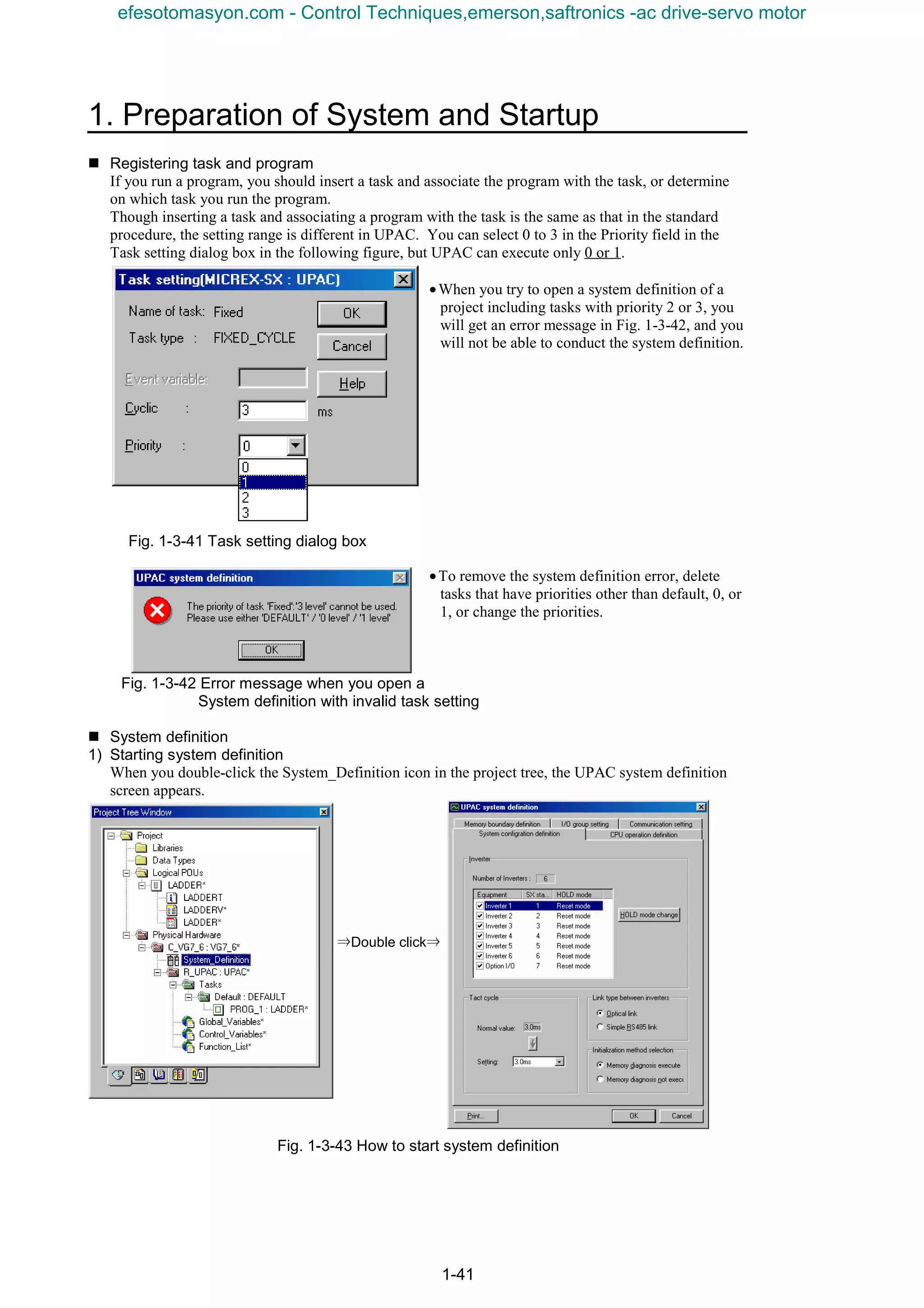
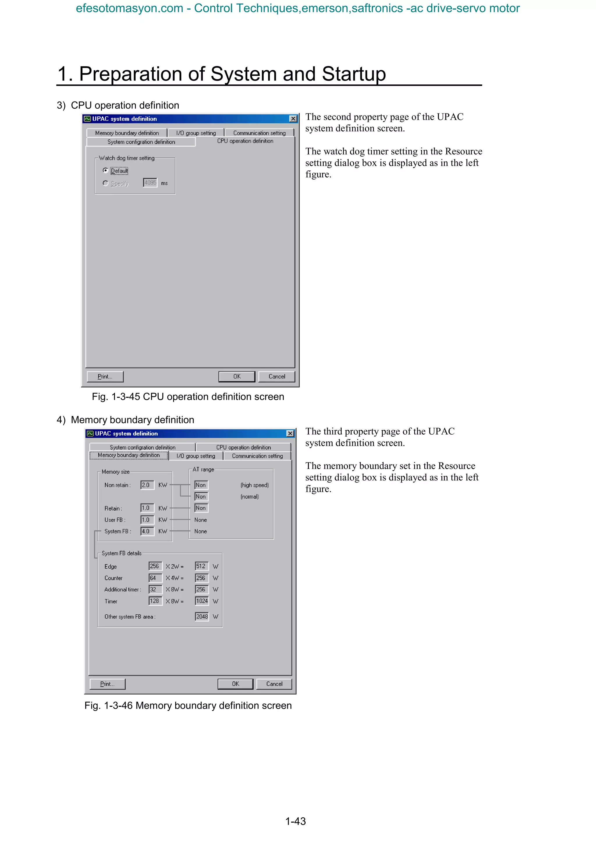
![1-42
The UPAC system definition screen includes the following property sheet with five property pages
classified by the setting item.
• System configration definition
• CPU operation definition
• Memory boundary definition
• I/O group setting
• Communication setting
2) System configration definition
The first property page of the UPAC system definition screen.
You define the hardware constitution such as inverter to be used and type of inter-inverter link on this
sheet.
Fig. 1-3-44 System configration definition screen
The following table describes the operation.
Table 1-3-2 Operation on System configration definition screen
Item Description
Number of inverters Displays whether six-inverter system or twelve-inverter system.
Equipment Mark the check box of a device you use (an inverter without check
mark will be considered as "not installed"). You can not remove
the last check mark.
SX station Displays the SX station number of inverters.
[HOLD mode change]
button (or double click
inverter list)
Specifies the HOLD mode of the inverter selected in the list
(HOLD mode/Reset mode).
You cannot select this button if the selected inverter is not
installed.
Tact cycle The normal value displays standard value (1ms to 3 ms)
automatically according to the number of inverters to be used.
Click the ↓ button to copy the normal value to the setting.
You can select the ↓ button only if the normal value and the
setting are different.
"Default (1.0ms), 1.0ms, 2.0ms, 3.0ms"are listed both for optical
link and simplified RS485 in the setting combo box and select
from them.
Smaller values than the normal value are masked and are not
available.
Link type between
inverters
Select "Optical link".
Initialization method
selection
Sets whether to execute the advanced memory diagnosis or not.
efesotomasyon.com - Control Techniques,emerson,saftronics -ac drive-servo motor](https://image.slidesharecdn.com/vg7upacmanual-140613044924-phpapp01/75/Vg7-upac-manual-54-2048.jpg)
![1-44
5) I/O group setting
The fourth property page of the UPAC
system definition screen.
This screen associates the UPAC task level
with the I/O data area of inverter and defines
refresh timing.
Fig. 1-3-47 I/O group setting screen
The following table describes the operation.
Table 1-3-3 Operation on I/O group setting screen
Item Description
Level Lists priorities of tasks included in the resource.
If you select (the priority of) a task, current setting will be
displayed.
Input selection Lists usage state of the I/O of the inverter under input signal,
output signal, and option I/O.
Sets the usage of input devices used as input for all points of
inverter input, inverter output, and option I/O at once.
Output selection Sets the mask of output devices used as output for all points of
inverter output and option I/O at once.
Selected
Sets the number of signals whose usage is ON for selected
devices.
[Details] button
(or double click an item)
Sets individual words for selected devices to enabled/disabled.
* You can set all devices whether a device is installed or not installed.
efesotomasyon.com - Control Techniques,emerson,saftronics -ac drive-servo motor](https://image.slidesharecdn.com/vg7upacmanual-140613044924-phpapp01/75/Vg7-upac-manual-56-2048.jpg)
![1. Preparation of System and Startup
1-45
Detailed operation on selection check boxes
Display and use as described below.
Advanced setting for individual words
If you click the [Details] button or
double click an item, the following
screen for the advanced setting
appears.
Fig. 1-3-48 Advanced setting screen for individual words
The following table describes the operation.
Table 1-3-4 Operation on Details setting screen
Item Description
Use check box Sets individual words to enabled/disabled.
Word No. Shows word number beginning with 1.
Name Shows signal name.
All button Set all points to ON/OFF at once. If more than half of all buttons are set to
OFF, then all buttons are set to ON at once, or otherwise set to OFF at
once.
• If all usage states are ON, displayed as ON .
• If some usage states are ON, displayed as gray .
• If all usage states are OFF, displayed as OFF .
• Each time you click the check box, the state changes as follows.
→ → → → →…
→ → → → →…
→ → → → →…
efesotomasyon.com - Control Techniques,emerson,saftronics -ac drive-servo motor](https://image.slidesharecdn.com/vg7upacmanual-140613044924-phpapp01/75/Vg7-upac-manual-57-2048.jpg)
![1-46
6) Communication setting
The fifth property page of the UPAC
system definition screen.
Sets the UPAC station number on
RS485 in the range from 1 to 255.
In addition to this, the setting in the
Communication setting dialog box
displayed when you click the
[Communication setting] button in the
Resource setting dialog box is
displayed.
Make sure to conform to the set value
of o40 "UPAC address" of VG7.
The factory setting of o40 is "100". If
the change is not necessary, you can
use the setting for RS485 station No.
of "100" on the screen to connect.
At H34, set the same communication
baud rate as the one shown on the left
screen.
Fig. 1-3-49 Communication setting screen
efesotomasyon.com - Control Techniques,emerson,saftronics -ac drive-servo motor](https://image.slidesharecdn.com/vg7upacmanual-140613044924-phpapp01/75/Vg7-upac-manual-58-2048.jpg)
![1. Preparation of System and Startup
1-47
n Printing UPAC system definition
You use the Properties of printer screen
displayed when you click the [Print (P)]
button on the property sheet to print the
system definition of UPAC.
When you click [Print (P)], the following
dialog box will appear.
To print other items than the system
definition, follow the standard procedure
using the menu item Print or Print Project.
Fig. 1-3-50 Printing system definition
efesotomasyon.com - Control Techniques,emerson,saftronics -ac drive-servo motor](https://image.slidesharecdn.com/vg7upacmanual-140613044924-phpapp01/75/Vg7-upac-manual-59-2048.jpg)
![1-48
Printed example of system definition
A printed example for twelve-unit system is listed below.
Project : UNTITLED C : D300WINUNTITLED
Update : 2000/03/09 13:21:21
Printed : 9/14/01 6:35:28 PM
----------------------------------------------------------------------------------------------------
[System configuration]
: Number of Inverters = 12
[Equipment] SX station No. mode
* Inverter 1 1 HOLD mode
Inverter 2 2 HOLD mode
* Inverter 3 3 RESET mode
* Inverter 4 4 HOLD mode
* Inverter 5 5 HOLD mode
* Inverter 6 6 HOLD mode
* Inverter 7 7 RESET mode
* Inverter 8 8 HOLD mode
* Inverter 9 9 HOLD mode
* Inverter 10 10 HOLD mode
* Inverter 11 11 HOLD mode
* Inverter 12 12 HOLD mode
* Option I/O 13 RESET mode
: Tact cycle = 3.0 ms
: Link type between inverters = Simple RS485 links
: Initialization method selection = Memory diagnosis execute
[CPU operation definition]
: Watch dog timer setting = Default
[Memory boundary definition] (AT Range)
: Non retain memory = 2.0 KW None (High)
None (Normal)
: Reatin memory = 1.0 KW None
: User FB memory = 1.0 KW None
: System FB memory = 4.0 KW None
: System FB memory detail
Edge detect = 256 × 2 W = 512 W
Counter = 64 × 4 W = 256 W
Addition timer = 32 × 8 W = 256 W
Timer = 128 × 8 W = 1024 W
Other system FB area = 2048 W
: Reserve memory size per POU
Use reserve memory = Not use
Non retain memory = 0
Retain memory = 0
User FB memory = 0
[I/O group setting] - Default
[Input selection - Input signal] Use inverter
1 2 3 4 5 6 7 8 9 10 11 12
1 Speed setting 4/frequency reference monitor o × × × × o × × × × × ×
2 Torque reference 2 o o × o × o × × × × × ×
3 Real speed (detected speed value) o × × × × o × × × × × ×
4 Control data (CW) (standard + DIOA option ; 16bit) o × × o × o × × × × × ×
5 Operation status (SW) o × × × × o × × × × × ×
6 Line speed input o × × o × o × × × × × ×
7 Ai of INV (Ai1) o × × × × o × × × × × ×
8 Ai of INV (Ai2) o × × o × o × × × × × ×
[Input selection - Option I/O input] Use
1 I/O Module DI 16 points ×
efesotomasyon.com - Control Techniques,emerson,saftronics -ac drive-servo motor](https://image.slidesharecdn.com/vg7upacmanual-140613044924-phpapp01/75/Vg7-upac-manual-60-2048.jpg)
![1. Preparation of System and Startup
1-49
[Output selection - Output signal] Use inverter
1 2 3 4 5 6 7 8 9 10 11 12
1 Speed setting 1/frequency reference (V/f) o × × o × × o × × × × ×
2 Torque reference 1 o × × o × × × × × × × ×
3 Control data (CW) o × × o × × × × × × × ×
4 Universal DO1 (standard + DIOA option ; 13bit) o × × o × × × × × × × ×
5 Acceleration time o × × o × × × × × × × ×
6 Deceleration time o × × o × × × × × × × ×
7 Torque limiter level 1 o × × o × × o × × × × ×
8 Torque limiter level 2 o × × o × × × × × × × ×
9 Speed setting 4/frequency reference (V/f) o × × o × × × × × × × ×
10 AO of INV (AO1) o × × o × × × × × × × ×
11 AO of INV (AO2) o × × o × × × × × × × ×
12 AO of INV (AO3) o × × o × × × × × × × ×
13 Dynamic switch 1 (DSW1) o × × o × × × × × × × ×
14 Dynamic switch 2 (DSW2) o × × o × × × × × × × ×
[Output selection - Option I/O output] Use
1 I/O Module DO 16 points ×
[Communication setting]
: RS485 station No. = 2
: Port = COM1
: Baudrate = 38400
: Stop bit = 1
: Data length = 8
: Parity = Even
: Timeout = 3000 ms
Fig. 1-3-51 Example of printed system definition
efesotomasyon.com - Control Techniques,emerson,saftronics -ac drive-servo motor](https://image.slidesharecdn.com/vg7upacmanual-140613044924-phpapp01/75/Vg7-upac-manual-61-2048.jpg)
![2-10
2.2.3.2 I/O group setting
I/O group setting is on the fourth property sheet of the UPAC system definition screen. The setting
method is described here.
Associate the task level of UPAC with the I/O data area of the inverter and define the refresh timing.
Fig. 2-2-4. I/O group setting screen
The operation method is described in the table below.
Table 2-2-5 Operation method in I/O group setting screen
Item Description Initial value
Level
The priority of the task included in the resource is listed.
Select the desired task (priority) to display the current setting.
Input selection
The I/O service state of the inverter is displayed in a list for each of
input signals, output signals, and option I/O.
The service state of the input devices used for inputting is set in a
batch for all inverter input points, all inverter output points or all option
I/O points.
All OFF
Output selection
The mask of the output devices used for outputting is set in a batch for
all inverter output points or option I/O points.
In a 6-unit system, up to 18W can be set; in a 12-unit system, up to 8W
can be set.
All OFF
Selected number The number of signals being used is displayed for the selected device.
[Details (D)] button
(Or double-click on
the item.)
Use and no use of each word can be set for the selected device.
* All devices can be set without relations to installation of each device.
efesotomasyon.com - Control Techniques,emerson,saftronics -ac drive-servo motor](https://image.slidesharecdn.com/vg7upacmanual-140613044924-phpapp01/75/Vg7-upac-manual-72-2048.jpg)
![2. Preparation and Basic Operation Examples
2-11
Detail operation method of selection check box
The check box is displayed or operated as described below.
• A check mark is placed ( ) if the service state of all devices is ON.
• A check mark is placed in the gray check box ( ) if the service state of some devices is ON.
• No check mark is placed if the service state of all devices is OFF.
• When clicked on, the state of the check box changes as shown below.
→ → → → →⋅⋅⋅
→ → → → →⋅⋅⋅
→ → → → →⋅⋅⋅
Detail setting method of each word
Press the [Details (D)] button or double-click on the item to display the detail setting screen shown in the
figure below.
Fig. 2-2-5 Detail setting screen for each word
The operation method is described as shown in the table below.
Table 2-2-6 Operation method of detail setting screen
Item Description
[Use] check box Set use or no use for each word.
Word No. The word number starting at “1” is displayed.
Name The signal name is displayed.
[All] button
All points are turned on or off in a batch. If OFF buttons are more than
half, all words are turned on; if not, all words are turned off.
efesotomasyon.com - Control Techniques,emerson,saftronics -ac drive-servo motor](https://image.slidesharecdn.com/vg7upacmanual-140613044924-phpapp01/75/Vg7-upac-manual-73-2048.jpg)
![2. Preparation and Basic Operation Examples
2-15
Table 2-3-1 LED blink and communication state
No. LED blinking pattern State of operation State transition
1 Blink at 500 ms intervals Correct operation
Optical communication is in correct operation
state.
When the option is turned on for the first time
after purchase, the function code setting is not
accurate and the No. 2 state is caused without
correct operation.
2
Three blinks at 100 ms
intervals then 500 ms OFF
Correct operation
(Communication link
not established)
Optical communication is not in correct operation
state.
• If the setting at switches SW1 or SW2 is wrong,
turn the power off and correct the setting, and
then turn the power on.
• For setting errors of function codes, correct the
settings and turn the power off then on again.
• If there is a broken wire in the communication
link, remove the cause of the broken wire.
3 Always ON (OFF) Option CPU error
An early ROM version of the main body of VG7 is
probable. Contact us.
(2) UPAC application check
CAUTION
• If the communication link is broken due to a broken wire or the like after the link is established
when the power is turned on, the inverter-to-inverter link error “Erb” is caused at all units. If the
communication link is broken before the power is turned on, the protective function is not effective
during stoppage. When the operation command (FWD or REV) is issued, the inverter-to-inverter
link error (Erb) is issued to activate the protective function, but design the UPAC application to
monitor the communication link to assure safety.
The communication state can be checked on the UPAC application side.
Use this function for confirmation upon system startup or for assurance of reliability of the
application during system stoppage.
Digital output
A digital output is issued in a UPAC + SI system when the communication link between optical
options is established.
Select one out of digital output terminals Y1 to Y5 and Y11 to Y18 (DIOA option) of the master
inverter where UPAC is installed, and assign 45; [0-D07].
45; [0-D07] 1: Communication link established (Correct operation in UPAC + SI)
0: Not established
Monitor the information of function code M14 “output terminal Y1 to Y18” at UPAC or connect
the DO output at the terminal block (DIOA: connector) to an external device.
Setting example
To assign the Y1 terminal for the check of communication link establishment, set 45;[0-D07] at
function code E15 “Y1 function selection” at the keypad panel.
The communication link is established without relations to the o38 “UPAC start/stop” stetting or
D300win control command if connection is correct.
2) Option recognition and ROM version confirmation
CAUTION
• Even if the optical option is physically installed, the communication link is not established if the
connector is not inserted completely or there is poor continuity. Be sure to check on the I/O check
screen of VG7 if “nSI-UP” is recognized correctly.
• The optical option is not compatible with VG7 of early ROM versions. The communication link is
not established with an early version. Be sure to check the ROM version at the maintenance
information indicated at the keypad panel. For any uncertainties about the version, contact us.
efesotomasyon.com - Control Techniques,emerson,saftronics -ac drive-servo motor](https://image.slidesharecdn.com/vg7upacmanual-140613044924-phpapp01/75/Vg7-upac-manual-77-2048.jpg)
![2. Preparation and Basic Operation Examples
2-19
2.4 Basic Operation Examples
In this section, a series of operations from concrete specification determination, preparation of programs,
downloading to UPAC, to VG7S control by UPAC are described through simple examples for giving
speed commands.
The most basic and important description is made here. Read through the description and fully understand.
Description assumes that you are already familiar with basic operations of D300win. For details of
operation of D300win, refer to the D300win user’s manual.
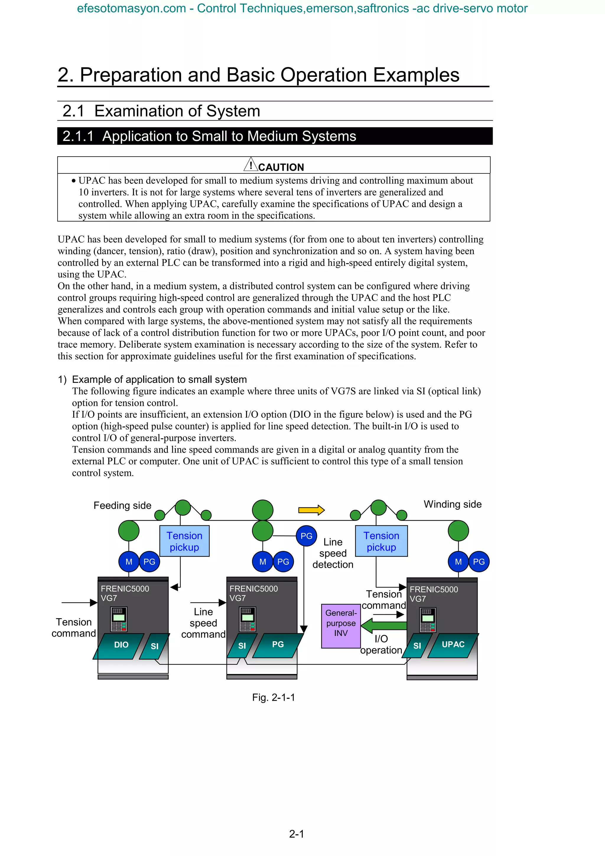
2.4.1 Determination of Specification
[Specification]
• Give VG7S the data set at function code UN0.01 as a speed command, to control the motor.
[Supplement]
VG7S can be operated with speed commands given at the keypad panel or data preset to multiple speeds.
While this is the standard function, you cannot use the user area (UN0.01 to 64) of the function code to
give speed commands. Though this is a simple example, the user can customize VG7S voluntarily using
UPAC.
2.4.2 Creating a Program
Create a program according to the specification.
Start D300win and select File (F), New Project.
The New Project selection screen opens. Select VG7_6 UPAC.
Fig. 2-4-1
efesotomasyon.com - Control Techniques,emerson,saftronics -ac drive-servo motor](https://image.slidesharecdn.com/vg7upacmanual-140613044924-phpapp01/75/Vg7-upac-manual-81-2048.jpg)
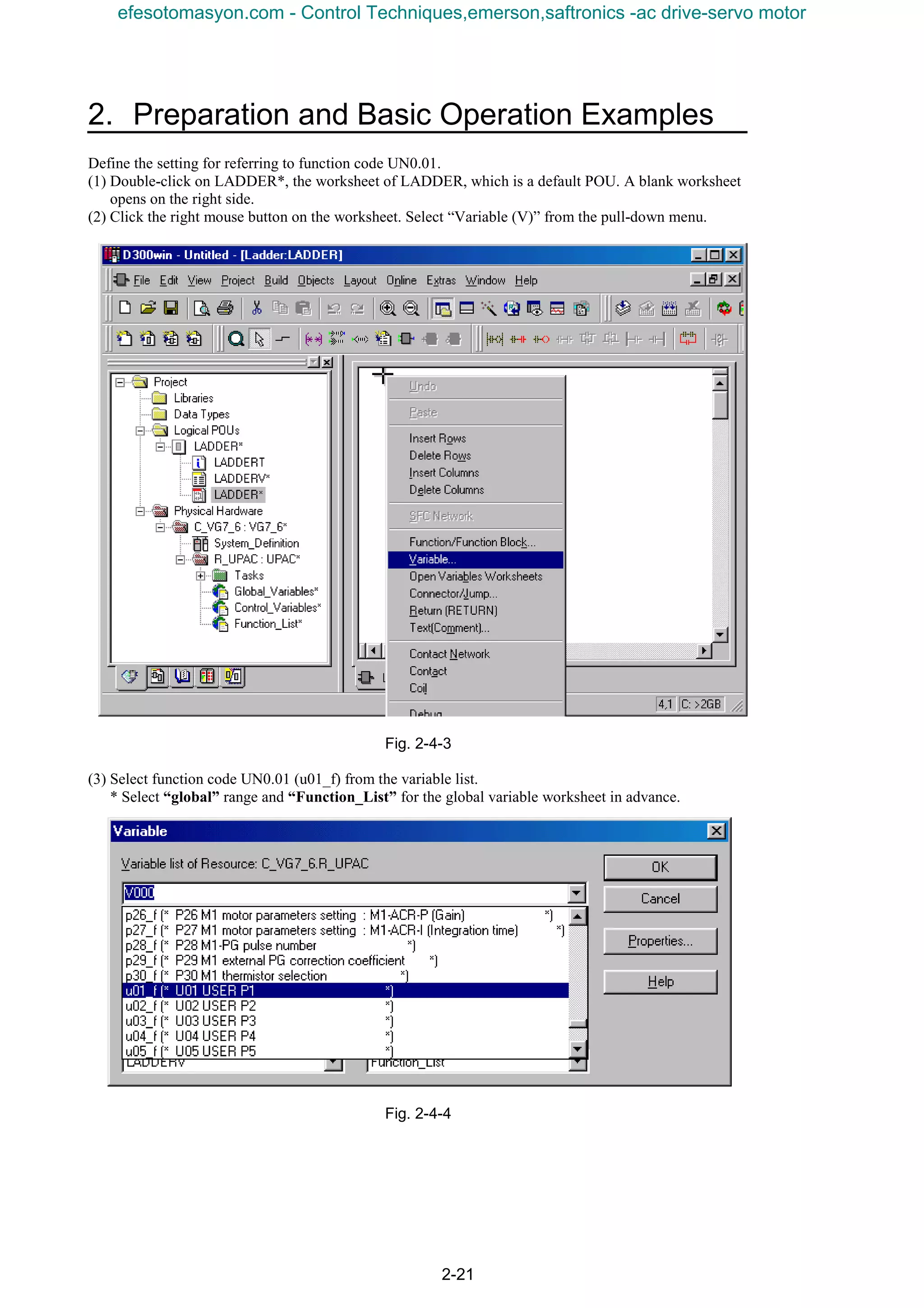
![2-22
Select [OK] in the previous page to return to the screen shown in the figure below.
If the character size is small, click on the + button shown in the circle to enlarge.
Fig. 2-4-5
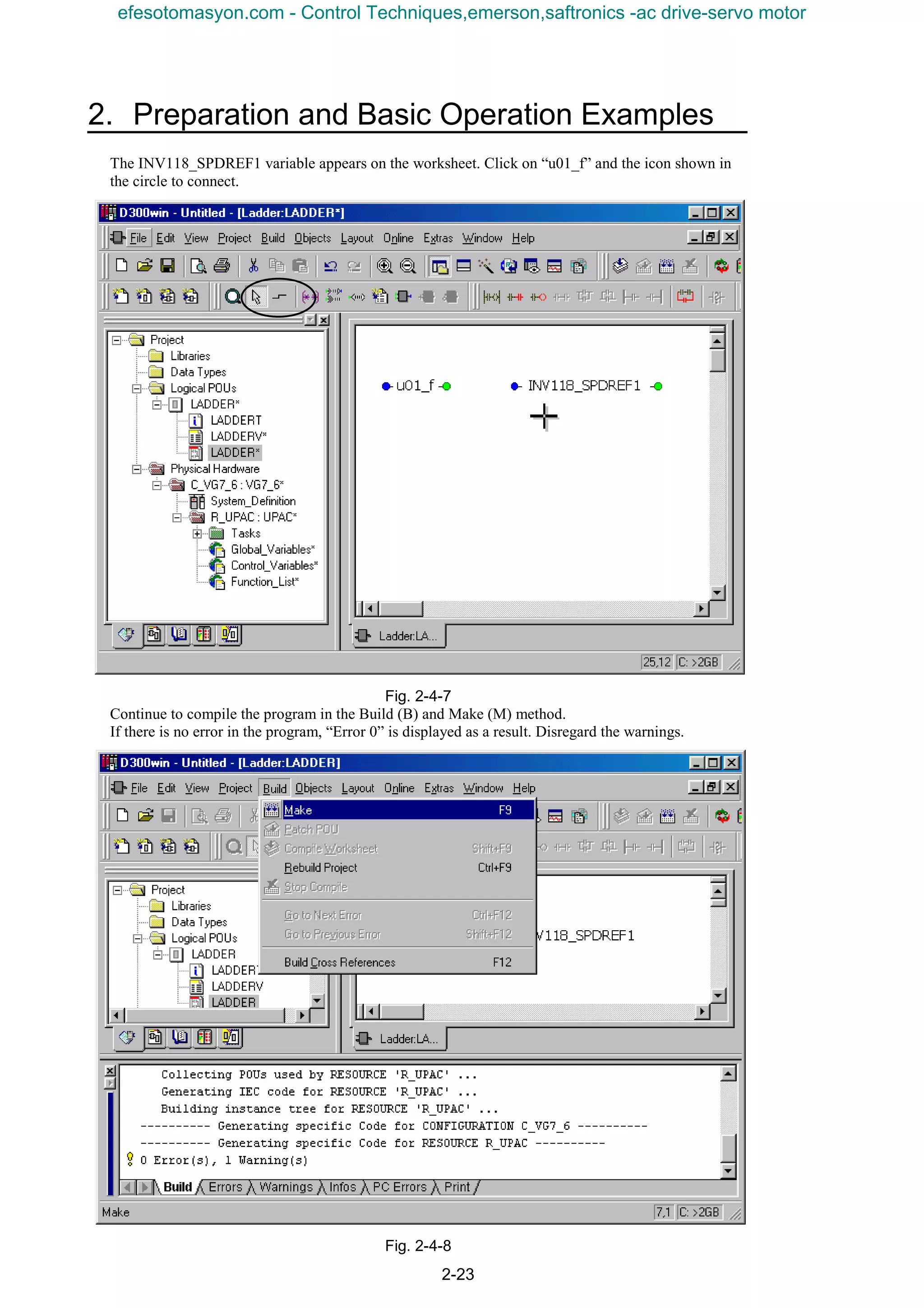
Next, connect the speed command given to VG7S, in the variable of u01_f.
(4) Select control variable speed setting 1 (INV118_SPDREF1) from the variable list.
* Select the “global” range and “Control Variables” for the global variable worksheet in advance.
Fig. 2-4-6
efesotomasyon.com - Control Techniques,emerson,saftronics -ac drive-servo motor](https://image.slidesharecdn.com/vg7upacmanual-140613044924-phpapp01/75/Vg7-upac-manual-84-2048.jpg)
![2-24
Double-click on System_Definition in the tree structure of the project.
Fig. 2-4-9
Speed setting 1 / frequency reference (V/f) only is checked with the I/O Group setting in the I/O group
setting.
Do not use the [All (A)] button to place check marks for all data items.
Fig. 2-4-10
efesotomasyon.com - Control Techniques,emerson,saftronics -ac drive-servo motor](https://image.slidesharecdn.com/vg7upacmanual-140613044924-phpapp01/75/Vg7-upac-manual-86-2048.jpg)
![2-26
3) Stopping UPAC
Click on the [Stop (S)] button of the control. A Stop dialog box appears. Select [Yes (Y)].
Fig. 2-4-13
4) Downloading
Check that the state of the control is “Stop” as shown in the figure below, and click on the [Download
(D)] button.
If the state of the control is “Run,” click on the [Stop (S)] button again to change to “Stop.”
Next, in the “Download loader => CPU” screen, place a check mark in all of the Program, Clear
retention memory (%M*.3) area, and System definition check boxes.
Fig. 2-4-14
efesotomasyon.com - Control Techniques,emerson,saftronics -ac drive-servo motor](https://image.slidesharecdn.com/vg7upacmanual-140613044924-phpapp01/75/Vg7-upac-manual-88-2048.jpg)
![2. Preparation and Basic Operation Examples
2-27
When downloading, the “downloading project” bar graph is displayed at the bottom of the screen to
show the progress of downloading. Though it depends on the size of the program, the process finishes
in about two to ten seconds.
Fig. 2-4-15
5) Resetting
Click on [Reset (R)] of the control. The Reset dialog box appears. Select [Yes (Y)]. The resetting
process takes about five seconds after [Yes] is clicked on. Wait for a while.
Fig. 2-4-16
efesotomasyon.com - Control Techniques,emerson,saftronics -ac drive-servo motor](https://image.slidesharecdn.com/vg7upacmanual-140613044924-phpapp01/75/Vg7-upac-manual-89-2048.jpg)
![2-28
6) Starting UPAC
Click on the [Start (A)] button of the control. The Start dialog box appears. Select [Yes (Y)]. Check
that the state of the control changes to “Run.”
Fig. 2-4-17
2.4.4 Simulating and Monitoring
1) Preparation
Click on the [Close] button to exit from the control screen.
Next, select [Online (N)], [Debug (D)].
Check that “00000” is displayed below the variables (u01_f, INV118_SPDREF1) on the worksheet.
In this state, the state of the UPAC is monitored at the real time.
Fig. 2-4-18
efesotomasyon.com - Control Techniques,emerson,saftronics -ac drive-servo motor](https://image.slidesharecdn.com/vg7upacmanual-140613044924-phpapp01/75/Vg7-upac-manual-90-2048.jpg)
![2. Preparation and Basic Operation Examples
2-29
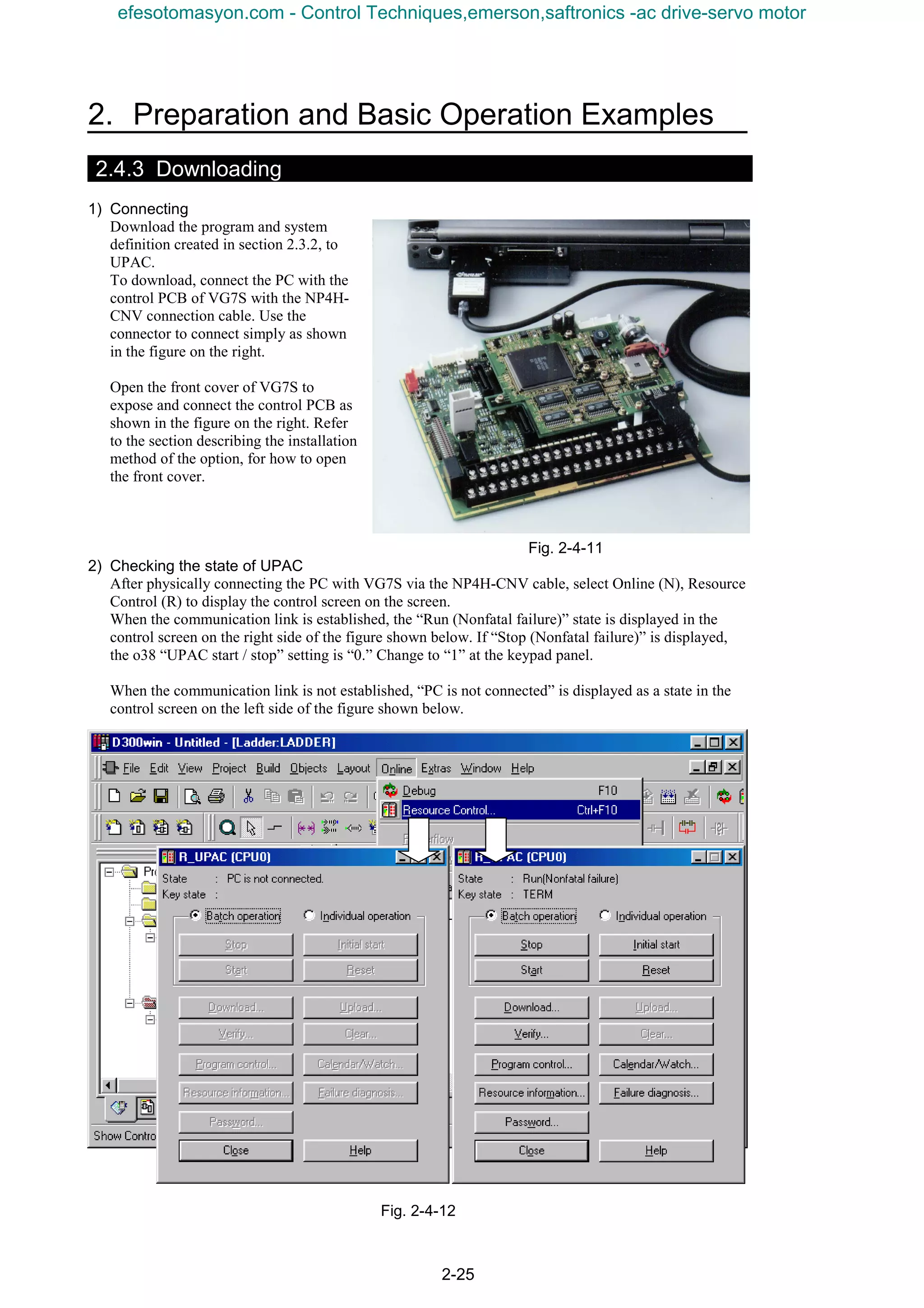
2) Entering data from the keypad panel
Change function code UN0.01 from “0” to “1000” at the keypad panel.
Check that “00000” changes to “01000” on the D300win monitor screen.
From this, it is known that UPAC refers to the UN0.01 data on the VG7S side and writes the data in
the speed interface of the IQ memory of UPAC.
Fig. 2-4-19
Next, change settings as follows.
F01 “Speed setting N1” = “0”
F02 “Operation” = “0”
F03 “Max. speed “ = “1500”
P01 “M1 control method” = “2”: Simulation mode
H30 “Link operation” = “0”
Turn off all contact signals related to the speed change such as multi-step operation.
[Explanation of setting]
Turn off the relevant contacts such as F01, F02 and H30 to validate operation commands and speed
commands entered at the keypad panel.
P01 makes simulation (speed control simulation) possible. This becomes inertia simulation for driving a
rotating body having an inertia of function code H51 “M1 load inertia.” At this time, the inverter does not
output a voltage, so that there is no need to connect a motor.
To drive an actual motor, refer to the VG7S User’s Manual for wiring and test operation of the motor.
efesotomasyon.com - Control Techniques,emerson,saftronics -ac drive-servo motor](https://image.slidesharecdn.com/vg7upacmanual-140613044924-phpapp01/75/Vg7-upac-manual-91-2048.jpg)

![3. VG7 Interface
3-1
3.1 Memory Interface
3.1.1 Giving Basic Commands
3.1.1.1 Operation command
CAUTION
• To operate from UPAC, short-circuit [FWD] and [REV] with [CM] at the terminal block. If only
one terminal is short-circuited, the motor rotates when o38 “UPAC start/stop” is set at “0: Stop.”
Be sure to short-circuit across [FWD] and [CM] and across [REV] and [CM].
(1) 6-unit system (broadcasting)
Table 3-1-1
Address No Name FS/BS Type Direction Remarks
%QW¨. 22 5
Control data (CW)
(standard + DIOA 16-bit)
Data type: 32 WORD UPAC→VG7S
¨ : 1 to 6 (INV1 to INV6)
(2) 12-unit system (broadcasting)
Table 3-1-2
Address No Name FS/BS Type Direction Remarks
%QW¨. 10 5
Control data (CW)
(standard + DIOA 16-bit)
Data type: 32 WORD UPAC→VG7S
¨ : 1 to 12 (INV1 to INV12)
There are two methods to issue an operation command ([FWD], [REV]): (1) operation at other than
UPAC and (2) operation at UPAC. The features of the operation command concerning UPAC are
operation under AND condition between external command and UPAC command and that the operation
command becomes invalid if the final command of both [FWD] and [REV] are ON.
1) How to use
The operation command is issued basically at the terminal block, keypad panel or communication
system. UPAC can issue or stop these external commands under the AND logic condition shown in
the figure below. This is the operation of UPAC.
On the other hand, when the UPAC SW is in the OFF state (in reference to the system definition
control data), operation can be made with external commands (other than those from UPAC) without
relations to UPAC.
Fig. 3-1-1
The memory for giving forward or reverse rotation command from UPAC is two bits in the lower
order of the control data (CW) in the word memory. “0” at the corresponding bit is OFF, while “1” is
ON.
Control data (CW): operation command: type [32]
15 8 7 0
0) [FWD] (Forward rotation operation command)
1) [REV] (Reverse rotation operation command)
2) to 15) [X1] to [X14], [RST]
UPAC SW
Selection of operation
(omitted)
Keypad
panel
[FWD]
FWD
Terminal
block
OPC-VG7-TL
Field bus
Option card
Forward rotation command
from UPAC
OPC-VG7-UPAC
OPC-VG7-SI(UPAC)
OFF
ON
COM
(link)
REMOTE
LOCAL
OPC-VG7-RS
Built-in RS485
AND
Forward rotation
command
efesotomasyon.com - Control Techniques,emerson,saftronics -ac drive-servo motor](https://image.slidesharecdn.com/vg7upacmanual-140613044924-phpapp01/75/Vg7-upac-manual-95-2048.jpg)
![3-2
Fig. 3-1-2
Fig. 3-1-3
2) Operation from outside (other than UPAC)
To operate without relations to UPAC
according to operation commands
from external device
Clear the control data (CW) check box in the I/O
Group setting screen of output definition at
System_Definition - I/O group setting of UPAC.
This operation makes operation of [FWD],
[REV], [X1] through [X14] operation commands
and control input commands of UPAC invalid. In
the figure on the right, the link from UPAC
concerning the forward rotation command is
canceled.
Because this causes word-level control including
[FWD], [REV], and [X1] through [X14], there is
the following precaution.
Note: To invalidate [FWD] and [REV] operations of UPAC while validating control over [X1] through [X14], place a check mark
at the control data (CW) and, according to the AND logic condition, OR the content of the corresponding memory with the
following data and write the result to the control data (CW).
0000 0000 0000 0011 (binary)
3) Operation from UPAC
To issue operation commands from
UPAC
Place a check mark at the control data
(CW) check box in the I/O Group
setting screen of output definition at
System_Definition - I/O group setting of UPAC.
This makes operation of [FWD], [REV], and
[X1] through [X14] operation commands and
control input commands of UPAC valid. In the
figure on the right, the operation from UPAC
concerning the forward rotation command is
validated.
Because of operation from UPAC, external
commands must be always turned on (short-
circuited at terminal block).
If only one terminal is short-circuited at the
terminal block when UPAC is stopped with “0”
at o38 “UPAC start/stop,” the motor keeps
operating. Make sure that both [FWD] and
[REV] are short-circuited at the terminal block.
Simultaneous inputs result in output
shutdown.
UPAC SW=OFF
Forward rotation command
from external device
OPC-VG7-UPAC
OPC-VG7-SI(UPAC)
OFF
ON
AND Forward rotation
command
Forward rotation
command of UPAC
UPAC SW=ON
Forward rotation command
from external device
Forward rotation
command of UPAC
OPC-VG7-UPAC
OPC-VG7-SI(UPAC)
OFF
ON
AND Forward rotation
command
efesotomasyon.com - Control Techniques,emerson,saftronics -ac drive-servo motor](https://image.slidesharecdn.com/vg7upacmanual-140613044924-phpapp01/75/Vg7-upac-manual-96-2048.jpg)
![3. VG7 Interface
3-3
3.1.1.2 Setting the speed
CAUTION
• When an operation command is given and the speed is written to speed setting 4 first, the motor
does not stop even if the operation command is turned off. Be sure to set the speed setting 4 data at
“0” before turning off the operation command.
Otherwise injuries may be caused.
(1) 6-unit system (broadcasting)
Table 3-1-3
Address No Name FS/BS Type Direction Remarks
%QW¨. 18 1
Speed setting 1/frequency
command (during V/f)
20000/Nmax INT UPAC→VG7S
Before multi-step
speed setting
%QW¨. 28 11
Speed setting 4/frequency
command (during V/f)
20000/Nmax INT UPAC→VG7S Before ASR input
¨ : 1 to 6 (INV1 to INV6)
(2) 12-unit system (broadcasting)
Table 3-1-4
Address No Name FS/BS Type Direction Remarks
%QW¨. 8 1
Speed setting 1/frequency
command (during V/f)
20000/Nmax INT UPAC→VG7S
Before multi-step
speed setting
%QW¨. 16 11
Speed setting 4/frequency
command (during V/f)
20000/Nmax INT UPAC→VG7S Before ASR input
¨ : 1 to 12 (INV1 to INV12)
There are two methods for setting the speed: operation of speed setting 1 and operation of speed setting 4.
Because speed setting 1 is inserted at the front stage of the control of VG7S, some of standard speed
control systems of VG7S (acceleration/deceleration calculator, speed limit, ASR input filter) can be used.
Because speed setting 4 is inserted immediately before ASR, it is useful for quick responses where speed
outputs of position control are reflected on the VG7S side.
1) How to use
To reflect the speed setting calculated at UPAC to VG7S, check the system definition then download
the system definition and reset to change the switches. In the figure below, speed setting 1 is changed.
Fig. 3-1-4
Place a check mark at the speed setting 1/frequency
command (during V/f) check box in the I/O Group
setting screen of output definition at UPAC
System_Definition - I/O group setting of the
D300win screen.
The speed setting data is converted into a 20000 scale.
Data × maximum speed/20000
(Example) To write “3000” for a maximum speed
setting of 1500 r/min
3000 × 1500 / 20000 = 225 r/min
UP/DOWN
初期値;零
Keypad panel speed
setting
=0
=1
=2
=3
(0~±10V)
(0~+10V)
∨
∧ FUNC
DATA
OFF
ON
UP指令
DOWN指令
×
ゲイン
F17
バイアス
F18
+ -[12]
Speed setting 1 from UPAC
UPAC SW
OPC-VG7-UPAC
OPC-VG7-SI(UPAC)
ASR input filter for
speed limiter
function calculating
S-curve
acceleration/
deceleration
ASR
OFF
ON
UPAC SW
Speed setting 4 from UPAC
Speed setting of other
than UPAC
Fig. 3-1-5
efesotomasyon.com - Control Techniques,emerson,saftronics -ac drive-servo motor](https://image.slidesharecdn.com/vg7upacmanual-140613044924-phpapp01/75/Vg7-upac-manual-97-2048.jpg)
![3-4
[Limitation]
When speed setting 4 is used, the acceleration/deceleration calculator does not function. Therefore
function code M14 or acceleration (ACC) and deceleration (DEC) in the “operation state” information of
IQ memory SW do not function correctly.
3.1.1.3 Auxiliary speed setting
CAUTION
• The auxiliary speed setting cannot be used when function code F01 or C25 is set at “0,” “3,” “4” or “5.”
The auxiliary speed setting can be given at UPAC.
(1) 6-unit system (broadcasting)
Table 3-1-5
Address No Name FS/BS Type Direction Remarks
%QW¨. 31 14 Auxiliary speed setting 20000/Nmax INT UPAC→VG7S
¨ : 1 to 6 (INV1 to INV6)
1) How to use
To reflect the auxiliary speed setting calculated by UPAC on VG7S, place a check mark in the system
definition then download the system definition and reset. In the figure below, connection is switched
to the auxiliary speed setting.
As shown in the block diagram, the auxiliary speed setting from UPAC is canceled if function code
F01 or C25 (validated one) is set at “0,” “3,” “4” or “5.” setting
Fig. 3-1-6
Place a check mark at the auxiliary speed
setting check box in the I/O Group setting
screen of output definition at UPAC
System_Definition - I/O group setting of the
D300win screen.
The auxiliary speed setting data is converted
into a 20000 scale.
Data × maximum speed/20000
(Example) To write “3000” for a maximum
speed setting of 1500 r/min
3000 × 1500 / 20000 = 225 r/min
Fig. 3-1-7
UP/DOWN
初期値;零
Speed setting at
keypad panel
=0
=1
=2
=3
(0~±10V)
(0~+10V)
∨
∧ FUNC
DATA
OFFON
UP指令
DOWN指令
×
ゲイン
F17
バイアス
F18
+ -【12】 UPAC SW
OPC-VG7-UPAC
OPC-VG7-SI(UPAC)
S-shaped
acceleration/
deceleration
calculation
Speed setting of other
than UPAC
Speed limiting
function, ASR input
filter
0
+
+ 1,2,6,7
0,3,4,5
F01
C25
Auxiliary speed
setting of UPAC
efesotomasyon.com - Control Techniques,emerson,saftronics -ac drive-servo motor](https://image.slidesharecdn.com/vg7upacmanual-140613044924-phpapp01/75/Vg7-upac-manual-98-2048.jpg)
![3. VG7 Interface
3-5
3.1.1.4 Torque reference
CAUTION
• After the operation command is turned on and a torque reference is given, the motor does not turn
off even if the operation command is turned off. To stop after giving a torque reference, turn the
operation command off and turn on coast-to-stop [BX].
Otherwise injuries may be caused.
(1) 6-unit system (broadcasting)
Table 3-1-6
Address No Name FS/BS Type Direction Remarks
%QW¨. 19 2 Torque reference 1 10000/100 % INT UPAC→VG7S Before torque limit
%QW¨. 29 12 Torque reference 2 10000/100 % INT UPAC→VG7S After torque limit
¨ : 1 to 6 (INV1 to INV6)
(2) 12-unit system (broadcasting)
Table 3-1-7
Address No Name FS/BS Type Direction Remarks
%QW¨. 19 2 Torque reference 1 10000/100 % INT UPAC→VG7S Before torque limit
¨ : 1 to 12 (INV1 to INV12)
There are two methods for the torque reference: operation of torque reference 1 and operation of torque
reference 2 (unavailable for a 12-unit system). Because torque reference 1 is inserted immediately after
the ASR output of the VG7S control, some of standard torque control systems (torque bias, torque limit)
of VG7S can be used. Torque reference 2 is inserted immediately before the torque current reference
calculation.
1) How to use
To reflect the torque reference calculated at UPAC on VG7S, place a check mark in the system
definition, download the system definition and reset. In the figure below, torque reference 1 is
switched.
Fig. 3-1-8
Place a check mark at the torque reference 1 check box
in the I/O Group setting screen of output definition at
UPAC System_Definition - I/O group setting of the
D300win screen.
The torque reference data is converted, assuming that
“10000” is the 100% torque (with the rated torque
being 100%).
Data/10000 = Torque %
(Example)To give a 60% torque reference, write
“6000.”
Fig. 3-1-9
[Limitation]
Because the acceleration/deceleration calculator does not function when the torque reference is used,
function code M14 or acceleration (ACC) and deceleration (DEC) in the SW “operation state”
information of the IQ memory do not function correctly.
ASR
OFF
+
+
Torque bias
+
Observer
calculation
Torque
limit
÷
Torque reference 1 from
UPAC
OPC-VG7-UPAC
OPC-VG7-SI(UPAC)
Torque reference 2 from UPAC
ON
OFF
ON
Magnetic-
flux
reference
Speed control system
UPAC SW UPAC SW
efesotomasyon.com - Control Techniques,emerson,saftronics -ac drive-servo motor](https://image.slidesharecdn.com/vg7upacmanual-140613044924-phpapp01/75/Vg7-upac-manual-99-2048.jpg)
![3-6
3.1.1.5 Torque limit
(1) 6-unit system (broadcasting)
Table 3-1-8
Address No Name FS/BS Type Direction Remarks
%QW¨. 26 9 Torque limiter level 1 10000/100 % INT UPAC→VG7S
%QW¨. 27 10 Torque limiter level 2 10000/100 % INT UPAC→VG7S
¨ : 1 to 6 (INV1 to INV6)
(2) 12-unit system (broadcasting)
Table 3-1-9
Address No Name FS/BS Type Direction Remarks
%QW¨. 14 9 Torque limiter level 1 10000/100 % INT UPAC→VG7S
%QW¨. 15 10 Torque limiter level 2 10000/100 % INT UPAC→VG7S
¨ : 1 to 12 (INV1 to INV12)
Operate torque limiter levels 1 and 2 according to the user specification (separation between driving and
braking, same level between driving and braking, etc.). Refer to the VG7S User’s Manual for how to use
the torque limit.
1) How to use
To reflect the torque limit calculated at UPAC on VG7S, place a check mark in the system definition,
download the system definition and reset. In the figure below, torque limiter 1 is switched.
Fig. 3-1-10
Place a check mark in the torque limiter level 1
check box in the I/O Group setting screen of output
definition at UPAC System_Definition - I/O group
setting of the D300win screen.
The torque limit data is converted, assuming that
“10000” is the 100% torque (with the rated torque
being 100%).
Data/10000 = Torque %
(Example) To give a 60% torque limit, write
“6000.”
Fig. 3-1-11
Ⅴ
Torque
limit
F40
F41
Torque limit mode 1
Torque limit mode 2
Torque limit value
1 of UPAC
UPAC SW
F42
3 [TL-REF1] =1
=3
=4
=2
S10
=0F44
Torque limit value
(level 1)
=5
[PIDOUT]
F43
Torque limit value
(level 2) selection
S11
F45
[PIDOUT]
PID calculation output
DIB
DIA
UPAC SW
OPC-VG7-DIA,DIB
ONON OFF
S03COM (link)
REMOTE
REMOTE
COM (link)
[DIB]
[DIA]
4 [TL-REF2]
OPC-VG7-UPAC
OPC-VG7-SI(UPAC)
Torque reference
Torque reference
after limiting
Other torque limit
elements
Torque limit value 2 of UPAC
Torque limit value
(level 2)
PID calculation output
Torque limit value
(level 1) selection
efesotomasyon.com - Control Techniques,emerson,saftronics -ac drive-servo motor](https://image.slidesharecdn.com/vg7upacmanual-140613044924-phpapp01/75/Vg7-upac-manual-100-2048.jpg)
![3. VG7 Interface
3-7
3.1.1.6 Torque bias
CAUTION
• After the operation command is turned on and a torque bias command is given, the motor does not
turn off even if the operation command is turned off. To stop after giving a torque bias command,
turn the operation command off and turn on coast-to-stop [BX].
Otherwise injuries may be caused.
The torque bias can be given at UPAC.
(1) 6-unit system (broadcasting)
Table 3-1-10
Address No Name FS/BS Type Direction Remarks
%QW¨. 30 13 Torque bias 10000/100 % INT UPAC→VG7S
¨ : 1 to 6 (INV1 to INV6)
The torque bias command is added immediately after the ASR output of VG7S control, some of the
standard torque control systems of VG7S (observer function, torque limit) can be used.
1) How to use
To reflect the torque bias command calculated at UPAC on VG7S, place a check mark in the system
definition, download the system definition and reset. In the figure below, the torque bias command is
switched from other torque bias.
Fig. 3-1-12
Place a check mark at the torque bias check box in the
I/O Group setting screen of output definition at UPAC
System_Definition - I/O group setting of the D300win
screen.
The torque bias data is converted, assuming that
“10000” is the 100% torque (with the rated torque being
100%).
Data/10000 = Torque %
(Example)To give a 60% torque bias, write “6000.”
Fig. 3-1-13
ASR
OFF
+
+
Torque bias
+
Observer
calculation
Torque
limit
÷
Torque bias from UPAC
OPC-VG7-UPAC
OPC-VG7-SI(UPAC)
ON
OFF
ON
Magnetic-
flux
reference
Speed control system
UPAC SW
UPAC SW
efesotomasyon.com - Control Techniques,emerson,saftronics -ac drive-servo motor](https://image.slidesharecdn.com/vg7upacmanual-140613044924-phpapp01/75/Vg7-upac-manual-101-2048.jpg)
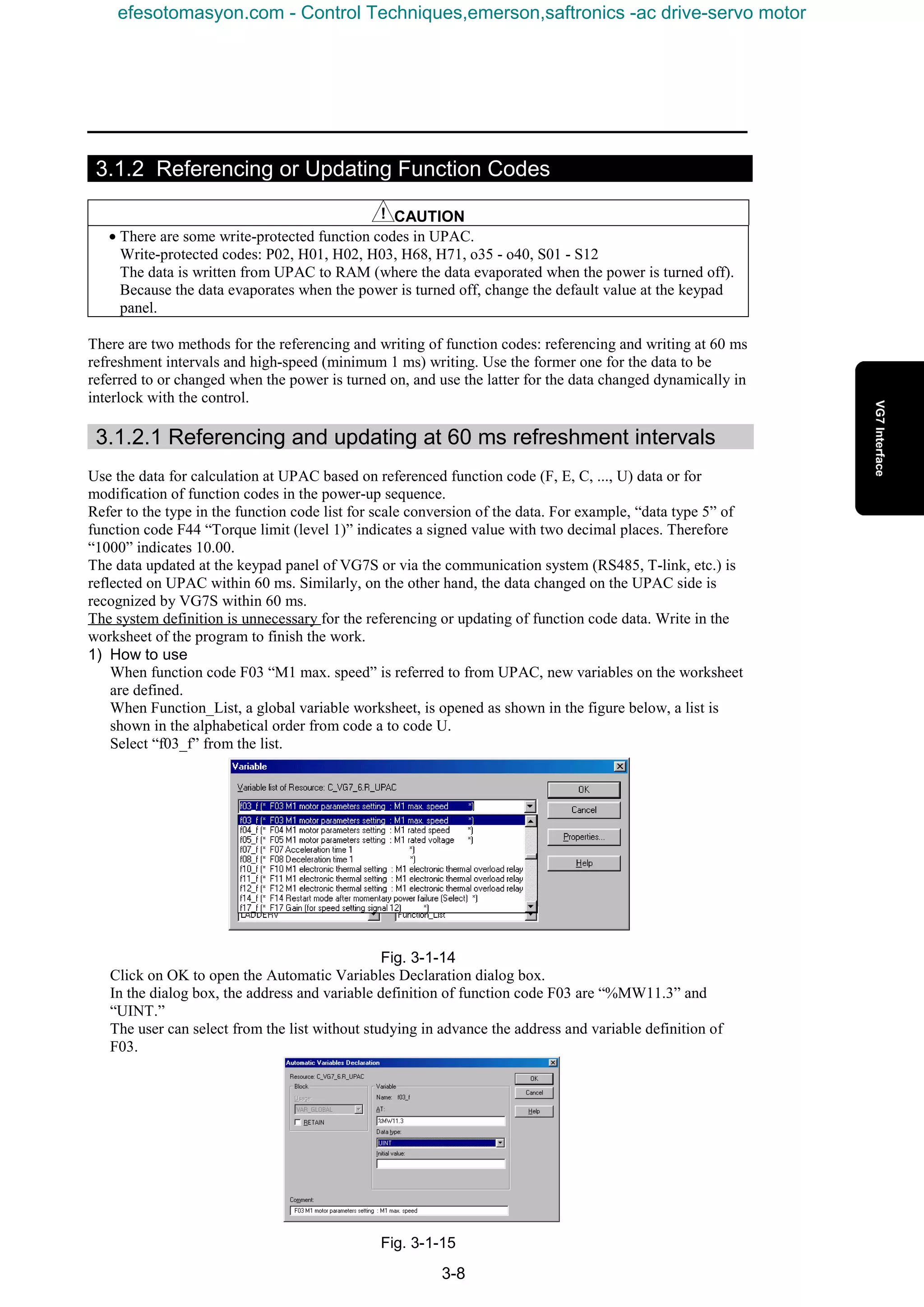
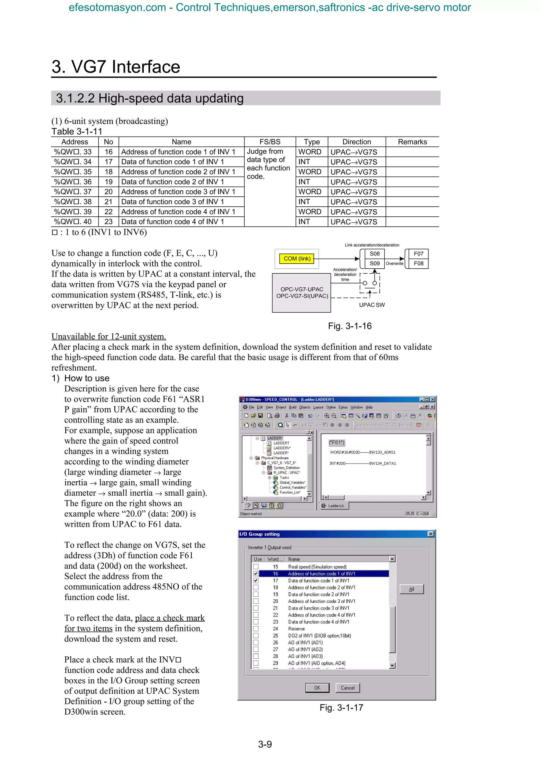
![3-10
3.1.2.3 Using user code
There are the following two methods for using the user code
(UNO).
1) Using the user code as a parameter for writing the
control and sequence program from UPAC
Assign a control parameter to UNO to adjust UNO using
the keypad panel or other standard equipment of VG7S
when you have no PC to be used for maintenance.
2) Placing a PLC for generalization and control outside
VG7S
Use UNO as a buffer for data exchange between the PLC
and UPAC.
Fig. 3-1-18
The user code is the 64 pieces of word of data (UN 0.01 to 64) shown in the table below.
Table 3-1-12
485NO Name of parameter
No.
485NO Link NO Name
Keypad panel
indication
Setting range Remarks
UNO.01 B01h DBh USER P1 USER P1 -32768 to 32767
UNO.02 B02h DCh USER P2 USER P2 -32768 to 32767
UNO.03 B03h DDh USER P3 USER P3 -32768 to 32767
UNO.04 B04h DEh USER P4 USER P4 -32768 to 32767
UNO.05 B05h DFh USER P5 USER P5 -32768 to 32767
UNO.06 B06h E0h USER P6 USER P6 -32768 to 32767
UNO.07 B07h E1h USER P7 USER P7 -32768 to 32767
UNO.08 B08h E2h USER P8 USER P8 -32768 to 32767
UNO.09 B09h E3h USER P9 USER P9 -32768 to 32767
UNO.10 B0Ah E4h USER P10 USER P10 -32768 to 32767
UNO.11 B0Bh - USER P11 USER P11 -32768 to 32767
to -
UNO.60 B3Ch - USER P60 USER P60 -32768 to 32767
UNO.61 B3Dh - USER P61 USER P61 -32768 to 32767
UNO.62 B3Eh - USER P62 USER P62 -32768 to 32767
UNO.63 B3Fh - USER P63 USER P63 -32768 to 32767
UNO.64 B40h - USER P64 USER P64 -32768 to 32767
[Limitations on usage]
• The range of the data and name are fixed as shown above. UPAC cannot control the indication shown
at the keypad panel.
• Only 10 words (UN 0.01 to 10 assigned to link NO) can be changed or referred to from the PLC.
• The UNO data is written to the RAM (evaporative memory) from UPAC. To retain memory even
after the power is turned off, there are the following two methods.
1) Write manually at the keypad panel.
2) Select “Retain” (battery backup) memory definition on the UPAC side.
Note: H01 “All save” cannot be accessed from UPAC.
FRENIC5000VG7S
Application of
UPAC
UNO
FRENIC5000VG7S
Application of
UPAC
UNO
Touch panel
PLC
efesotomasyon.com - Control Techniques,emerson,saftronics -ac drive-servo motor](https://image.slidesharecdn.com/vg7upacmanual-140613044924-phpapp01/75/Vg7-upac-manual-104-2048.jpg)
![3. VG7 Interface
3-11
3.1.2.4 Operation of acceleration/deceleration time
(1) 6-unit system (broadcasting)
Table 3-1-13
Address No Name FS/BS Type Direction Remarks
%QW¨. 24 7 Acceleration time 1/0.1s INT VG7S→UPAC
%QW¨. 25 8 Deceleration time 1/0.1s INT VG7S→UPAC
¨ : 1 to 6 (INV1 to INV6)
(2) 12-unit system (broadcasting)
Table 3-1-14
Address No Name FS/BS Type Direction Remarks
%QW¨. 12 7 Acceleration time 1/0.1s INT VG7S→UPAC
%QW¨. 13 8 Deceleration time 1/0.1s INT VG7S→UPAC
¨ : 1 to 12 (INV1 to INV12)
There are two methods to operate the acceleration time and deceleration time from UPAC: accessing the
I/Q memory and writing the function code.
Write the function code (F07, F08, ...) according to the
method described in section 3.1.2.
Access the IQ memory according to the method described in
section 3.1.1. The F07 and F08 data is overwritten as shown
in the block diagram on the right. Therefore validate
parameter 1 ([RT1], [RT2] = OFF, OFF) when using the IQ
memory.
S08 and S09 written by the link system are overwritten with
the data of UPAC.
Fig. 3-1-19
3.1.3 Operating Inputs and Outputs
3.1.3.1 Referring to digital inputs
CAUTION
• To use control inputs [X1] to [X9] and [X11] to [X14] (DIOA) only for monitoring from UPAC,
set function codes E01 to E13 at “25” to assign each control input to universal DI [U-DI] so that
activation and deactivation of the contact do not give effects on the control function of the main
body.
(1) 6-unit system (not applicable to broadcasting)
Table 3-1-15
Address No Name FS/BS Type Direction Remarks
%IW¨. 5 6
Control data (CW)
(standard + DIOA, 16-bit)
Data type: 32 INT VG7S→UPAC
Define [U-DI] to allow UPAC to
use the [DI] terminal for the
control input.
%IW¨. 13 14
DI of INV¨
(DIOB option, 16-bit)
Data type 26 INT VG7S→UPAC
Extended I/O exclusively for
UPAC
¨ : 1 to 6 (INV1 to INV6)
(2) 12-unit system (not applicable to broadcasting)
Table 3-1-16
Address No Name FS/BS Type Direction Remarks
%IW¨. 3 6
Control data (CW)
(standard + DIOA, 16-bit)
Data type: 32 INT VG7S→UPAC
Define [U-DI] to allow UPAC to
use the [DI] terminal for the
control input.
¨ : 1 to 12 (INV1 to INV12)
The digital inputs referred to by UPAC are the standard DI ([X1] to [X9]), DIOA option ([X11] to [X14])
and DIOB option ([X21] to [X36]) (not for 12-unit system).
F07
F08
COM (link)
S08
S09
Link acceleration/deceleration
Acceleration/
deceleration
time
UPAC SW
Overwrite
OPC-VG7-UPAC
OPC-VG7-SI(UPAC)
efesotomasyon.com - Control Techniques,emerson,saftronics -ac drive-servo motor](https://image.slidesharecdn.com/vg7upacmanual-140613044924-phpapp01/75/Vg7-upac-manual-105-2048.jpg)
![3-12
1) How to use
The control input can refer to
terminal information ([X1] to [X9],
[X11] to [X14], and [X21] to [X36])
and communication input
information ([X1] to [X9], [RST],
and [X11] to [X14]).
The communication input
information needs the setting of
function code H30 “link operation.”
For details of the communication
input, refer to the corresponding
description in Chapter 4.
To refer to the data, place a check
mark in the system definition,
download the system definition, and
reset.
Place a check mark at the check box
of the corresponding data items in
the I/O Group setting screen of
output definition at UPAC
System_Definition - I/O group setting
of the D300win screen.
Each control input must be assigned to universal DI if referencing only is the purpose when the
ON/OFF state of [X1] to [X9] and [X11] to [X14] is referred to from UPAC. For example, [X1] is
assigned to [SS0] in the factory shipment setting. When this signal is turned on, multi-step speed 1
becomes valid. To avoid this, set [U-DI] to refer to the state of [X1] without using the multi-step
speed function.
2) Decomposition of word data
The data of the control input is referred to in word information. The data format is as shown below.
(1) Control data (CW): operation command: type [32]
15 8 7 0
0) [FWD] (Forward operation command)
1) [REV] (Reverse operation command)
2) to 15) [X1] to [X14], [RST]
(2) DIOB option: type [26]
15 8 7 0
0) to 15) [X21] to [X36]
After acquiring, develop the word information into bits. An example in the IL language is shown
below.
Fig. 3-1-20
efesotomasyon.com - Control Techniques,emerson,saftronics -ac drive-servo motor](https://image.slidesharecdn.com/vg7upacmanual-140613044924-phpapp01/75/Vg7-upac-manual-106-2048.jpg)
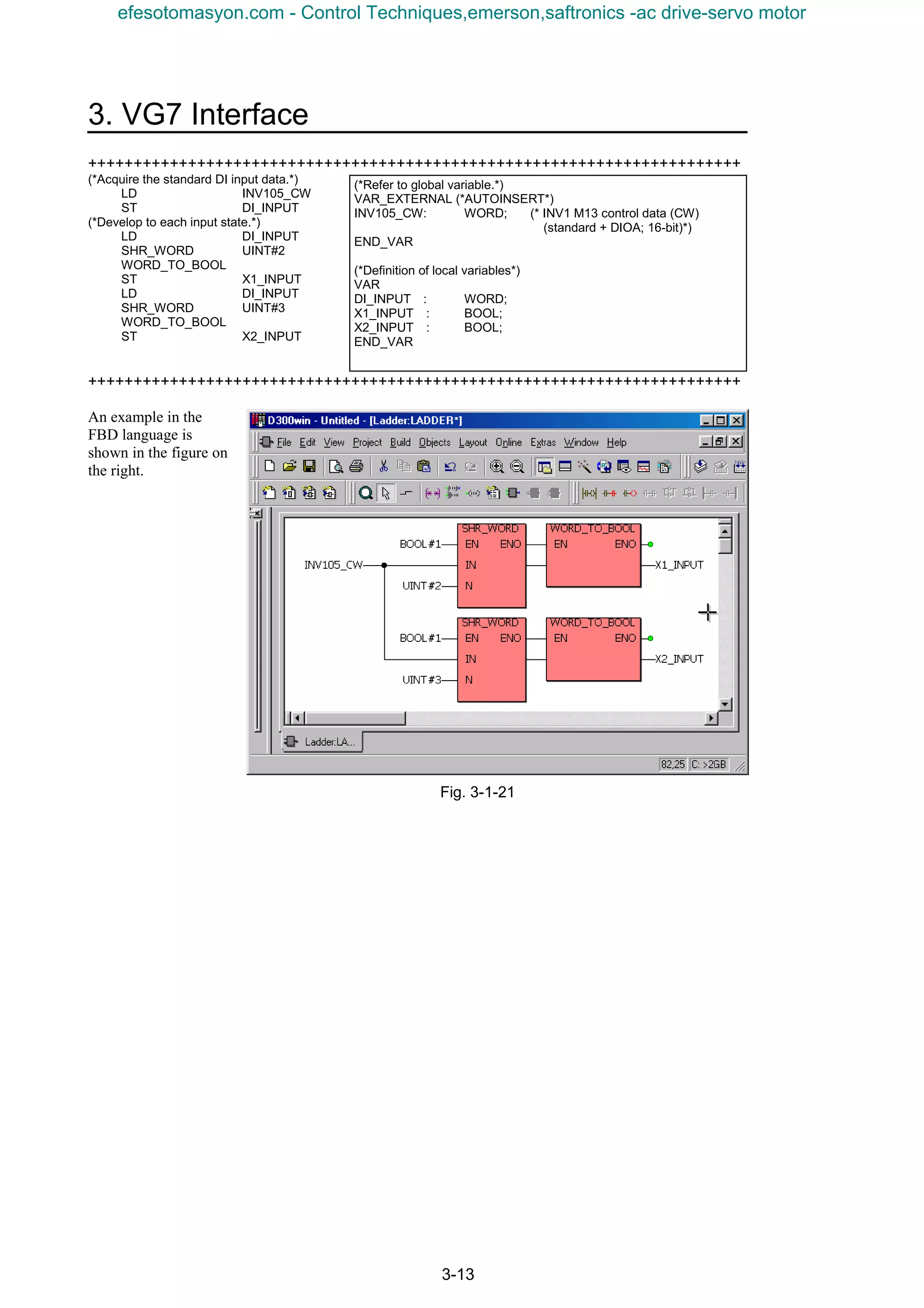
![3-14
3.1.3.2 Referring to analog inputs
CAUTION
• To use analog inputs [Ai1], [Ai2], [Ai3], and [Ai4] (AIO option) only for monitoring from UPAC,
set function codes E49 to E52 at “14” to assign each analog input to universal AI [U-AI] so that the
analog inputs do not give effects on the control function of the main body.
(1) 6-unit system (not applicable to broadcasting)
Table 3-1-17
Address No Name FS/BS Type Direction Remarks
%IW¨. 14 15 Ai of INV1 (Ai1) ±4000h/±10V INT VG7S→UPAC
%IW¨. 15 16 Ai of INV1 (Ai2) ±4000h/±10V INT VG7S→UPAC
%IW¨. 16 17 Ai of INV1 (AIO option, Ai3) ±4000h/±10V INT VG7S→UPAC
%IW¨. 17 18 Ai of INV1 (AIO option, Ai4) ±4000h/±10V INT VG7S→UPAC
Define [U-AI] to allow UPAC
to use the [AI] terminal for
control inputs.
¨ : 1 to 6 (INV1 to INV6)
(2) 12-unit system (not applicable to broadcasting)
Table 3-1-18
Address No Name FS/BS Type Direction Remarks
%IW¨. 6 15 Ai of INV1 (Ai1) ±4000h/±10V INT VG7S→UPAC
%IW¨. 7 16 Ai of INV1 (Ai2) ±4000h/±10V INT VG7S→UPAC
Define [U-AI] to allow UPAC
to use the [AI] terminal for
control inputs.
¨ : 1 to 12 (INV1 to INV12)
The analog inputs referred to by UPAC are the standard AI ([Ai1] and [Ai2]) and AIO option ([Ai3] and
[Ai4]) (not for 12-unit system).
1) How to use
To refer to the data, place a check mark in the system definition, download the system definition and
reset.
Place a check mark at the check box of the corresponding
data items in the I/O Group setting screen of output
definition at UPAC System_Definition - I/O group
setting of the D300win screen.
Each input must be assigned to universal AI [U-AI] when
the state of [Ai1], [Ai2], [Ai3] and [Ai4] is referred to
from UPAC.
Each analog input is assigned to [OFF] (input shutoff
signal) in the factory shipment setting.
A ±10V analog input is converted into
a ±4000h (±16384d) digital value and
read into UPAC.
The standard function includes the gain,
bias, filter, increment/decrement limiter,
polarity inversion, and zero hold. For
details, refer to Chapter 4 of the User’s
Manual for the main body.
The state of analog inputs can be
checked using the I/O check at the
keypad panel. If “15555” (type: INT) is
displayed when the AI_DATA variable
is monitored, the actual input is 9.49V
(10V x 15555/16384) when gain is “1”
and bias is “0.”
Fig. 3-1-22
efesotomasyon.com - Control Techniques,emerson,saftronics -ac drive-servo motor](https://image.slidesharecdn.com/vg7upacmanual-140613044924-phpapp01/75/Vg7-upac-manual-108-2048.jpg)
![3. VG7 Interface
3-15
3.1.3.3 Operation of digital output
CAUTION
• To operate control outputs [Y1] to [Y5A] and [Y11] to [Y18] (DIOA) from UPAC, set function
codes E15 to E27 at “25” to assign each output to the universal DO [U-DO] so that the control state
of VG7S (running, speed agreement, etc.) do not give effects on the output signals.
(1) 6-unit system (broadcasting)
Table 3-1-19
Address No Name FS/BS Type Direction Remarks
%QW¨. 23 6
Universal DO1
(standard + DIOA option, 13-bit)
Data type: 33 WORD UPAC→VG7S Define [U-DO].
%QW¨. 42 25
Universal DO2
(DIOB option, 10-bit)
Data type: 37 WORD UPAC→VG7S
Extension I/O exclusively
for UPAC
¨ : 1 to 6 (INV1 to INV6)
(2) 12-unit system (broadcasting)
Table 3-1-20
Address No Name FS/BS Type Direction Remarks
%QW¨. 11 6
Universal DO1
(standard + DIOA option, 13-bit)
Data type: 33 WORD UPAC→VG7S Define [U-DO].
¨ : 1 to 12 (INV1 to INV12)
The digital outputs that can be controlled by UPAC are the standard DO ([Y1] to [Y5A]), DIOA option
([Y11] to [Y18]), and DIOB option ([Y21] to [Y30]) (not for 12-unit system).
1) How to use
To operate the data, place a check mark in the
system definition, download the system
definition, and reset.
Place a check mark at the check box of the
corresponding data items in the I/O Group
setting screen of output definition at UPAC
System_Definition - I/O group setting of the
D300win screen.
To operate [Y1] to [Y5A] and [Y11] to [Y18]
from UPAC, assign each control output to the
universal DO so that the control state of the
main body of VG7S is not reflected on the
output (running, speed agreement, etc.).
For example, [Y1] is assigned to speed existence
[N-EX] in the factory shipment value. When the
motor rotates actually, [Y1] is turned on or off
according to the speed. To operate [Y1] from
UPAC only, assign the [U-DO] function to stop
reflection of the state inside the control.
Fig. 3-1-23
efesotomasyon.com - Control Techniques,emerson,saftronics -ac drive-servo motor](https://image.slidesharecdn.com/vg7upacmanual-140613044924-phpapp01/75/Vg7-upac-manual-109-2048.jpg)
![3-16
2) Composition into word data
The control output data is composed in a word data before it is reflected. The data format is as shown
below.
(1) DO1 of INV¨ (standard + DIOA; 13-bit): type [33]
15 8 7 0
0) to 4) [Y1] to [Y5A]
8) to 15) [Y11] to [Y18]
(2) DO2 of INV¨ (DIOB option; 10-bit): type [27]
15 8 7 0
0) to 9) [Y21] to [Y30]
Compose the bits into word data before reflecting. An example of composition in the IL language is
shown below.
+++++++++++++++++++++++++++++++++++++++++++++++++++++++++++++++++++++++++++
(*Acquire output information.*)
LD Y1_OUTPUT
BOOL_TO_WORD
SHL_WORD UINT#0
ST DO_OUTPUT
LD Y2_OUTPUT
BOOL_TO_WORD
SHL_WORD UINT#1
OR DO_OUTPUT
ST INV123_UNIDO1
+++++++++++++++++++++++++++++++++++++++++++++++++++++++++++++++++++++++++++
Fig. 3-1-24
(*Refer to global variable.*)
VAR_EXTERNAL (*AUTOINSERT*)
INV123_UNIDO1 :WORD;(*INV1 S07 DO1 of INV1
(standard + DIOA; 13-bit)*)
END_VAR
(*Definition of local variables*)
VAR
DO_OUTPUT: WORD;
Y1_OUTPUT: BOOL;
Y1_OUTPUT: BOOL;
END_VAR
efesotomasyon.com - Control Techniques,emerson,saftronics -ac drive-servo motor](https://image.slidesharecdn.com/vg7upacmanual-140613044924-phpapp01/75/Vg7-upac-manual-110-2048.jpg)
![3. VG7 Interface
3-17
3.1.3.4 Operation of analog output
CAUTION
• To control analog outputs [A01] to [A03], [A04] and [A05] (AIO option) from UPAC, assign
function codes E69 to E73 at “30” to set the analog outputs to the universal AO [U-AO] so that the
control function of the main body does not give effects.
(1) 6-unit system (broadcasting)
Table 3-1-21
Address No Name FS/BS Type Direction Remarks
%QW¨. 43 26 AO of INV1 (AO1) ±4000h/±10V INT UPAC→VG7S
%QW¨. 44 27 AO of INV1 (AO2) ±4000h/±10V INT UPAC→VG7S
%QW¨. 45 28 AO of INV1 (AO3) ±4000h/±10V INT UPAC→VG7S
%QW¨. 46 29 AO of INV1 (AIO option, AO4) ±4000h/±10V INT UPAC→VG7S
%QW¨. 47 30 AO of INV1 (AIO option, AO5) ±4000h/±10V INT UPAC→VG7S
Define [U-AO] to allow
UPAC to control the
[AO] terminal.
¨ : 1 to 6 (INV1 to INV6)
(2) 12-unit system (broadcasting)
Table 3-1-22
Address No Name FS/BS Type Direction Remarks
%QW¨. 17 26 AO of INV1 (AO1) ±4000h/±10V INT UPAC→VG7S
%QW¨. 18 27 AO of INV1 (AO2) ±4000h/±10V INT UPAC→VG7S
%QW¨. 19 28 AO of INV1 (AO3) ±4000h/±10V INT UPAC→VG7S
Define [U-AO] to allow
UPAC to control the
[AO] terminal.
¨ : 1 to 12 (INV1 to INV12)
The analog outputs controlled by UPAC are the standard AO ([AO1], [AO2] and [AO3]) and AIO option
([AO4] and [AO5]) (not for 12-unit system).
1) How to use
To refer to the data, place a check mark in the system definition, download the system definition, and
reset.
Place a check mark at the check box of the
corresponding data items in the I/O Group setting screen
of output definition at UPAC System_Definition - I/O
group setting of the D300win screen.
To operate the state of [AO1], [AO2], [AO3], [AO4]
and [AO5] from UPAC, assign each output to the
universal AO [U-AO].
Each analog output is assigned to various purposes such
as the torque current command in the factory shipment.
To shut off these functions, assignment of [U-AO] is
necessary.
A ±4000h (±16384d) digital amount is
calculated and converted by UPAC into a
±10V analog output.
The gain, bias and filter functions can be
used as standard features. Refer to Chapter
4 for details.
Use the I/O check at the keypad panel to
monitor the analog output. If “15555”
(type: INT) is displayed when an
AO_DATA variable is monitored as shown
in the figure on the right, the actual output
is 9.49V (10V x 15555/16384) when the
gain is “1” and the bias is “0.”
Fig. 3-1-25
efesotomasyon.com - Control Techniques,emerson,saftronics -ac drive-servo motor](https://image.slidesharecdn.com/vg7upacmanual-140613044924-phpapp01/75/Vg7-upac-manual-111-2048.jpg)
![3-18
3.1.4 Monitoring Data
UPAC can refer to the speed, torque data, and operation state (running, accelerating, etc.).
There are two types of data: high-speed sampling using the IQ area, and 60ms sampling using the M code
area. Using the former one, you can refer to all the data of VG7S. Using the M code area, you can refer to
the data of only the VG7S equipped with UPAC.
3.1.4.1 Speed command monitor (high speed)
(1) 6-unit system (not applicable to broadcasting)
Table 3-1-23
Address No Name FS/BS Type Direction Remarks
%IW¨. 0 1
Speed setting 4/frequency
reference monitor
20000/Nmax INT VG7S→UPAC Before ASR input
%IW¨. 7 8
Speed setting 1/frequency
reference (during V/f)
20000/Nmax INT VG7S→UPAC
Before multi-step speed
setting
¨ : 1 to 6 (INV1 to INV6)
(2) 12-unit system (not applicable to broadcasting)
Table 3-1-24
Address No Name FS/BS Type Direction Remarks
%IW¨. 0 1
Speed setting 4/frequency
reference monitor
20000/Nmax INT VG7S→UPAC Before ASR input
¨ : 1 to 12 (INV1 to INV12)
The speed command monitor refers to the data of speed setting 1 (not for the 12-unit system) before
multi-step speed calculation, and speed setting 4 refers to the data immediately before ASR input.
1) How to use
Fig. 3-1-26
Place a check mark at the speed setting
1/frequency command (during V/f) check box
in the I/O Group setting screen of output
definition at UPAC System_Definition - I/O
group setting of the D300win screen. Next,
download the system definition, and reset.
The speed setting data is converted into the
scale where “20000” indicates the maximum
speed.
Data × max. speed/20000
(Example)If “3000” is obtained when data is
referred in a system where the maximum speed
is set at 1500 r/min.
3000 × 1500/20000=225r/min
Fig. 3-1-27
UP/DOWN
初期値;零
Keypad panel speed setting
=0
=1
=2
=3
(0~±10V)
(0~+10V)
∨
∧ FUNC
DATA
OFF
ON
UP指令
DOWN指令
×
ゲイン
F17
バイアス
F18
+ -
Speed setting 1
UPAC SW
OPC-VG7-UPAC
OPC-VG7-SI(UPAC)
ASR input filter for
speed limiter
function calculating
S-curve
acceleration/
deceleration
ASR
OFF
ON
UPAC SW
Speed setting 4
Speed setting of other
than UPAC[12]
efesotomasyon.com - Control Techniques,emerson,saftronics -ac drive-servo motor](https://image.slidesharecdn.com/vg7upacmanual-140613044924-phpapp01/75/Vg7-upac-manual-112-2048.jpg)
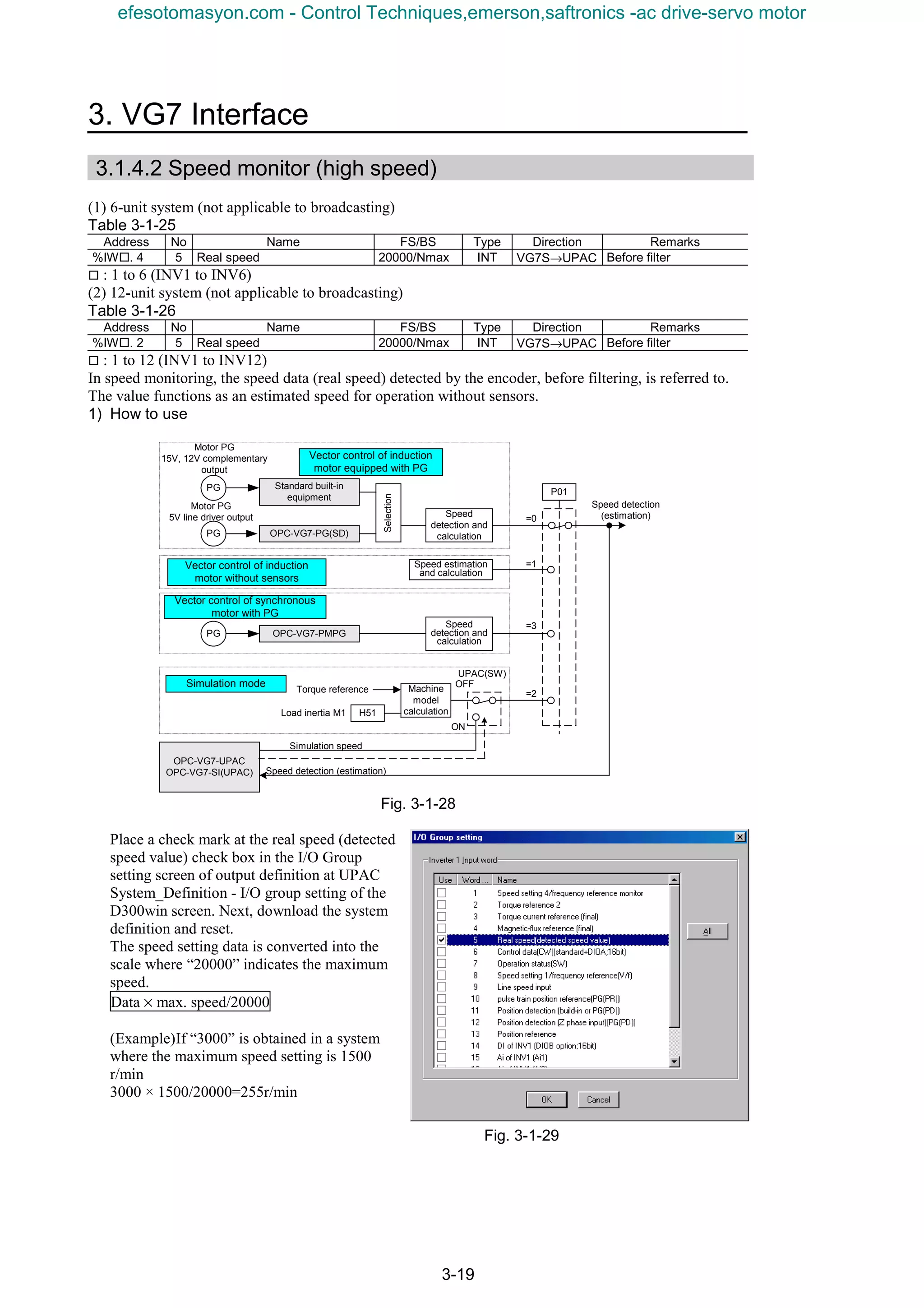
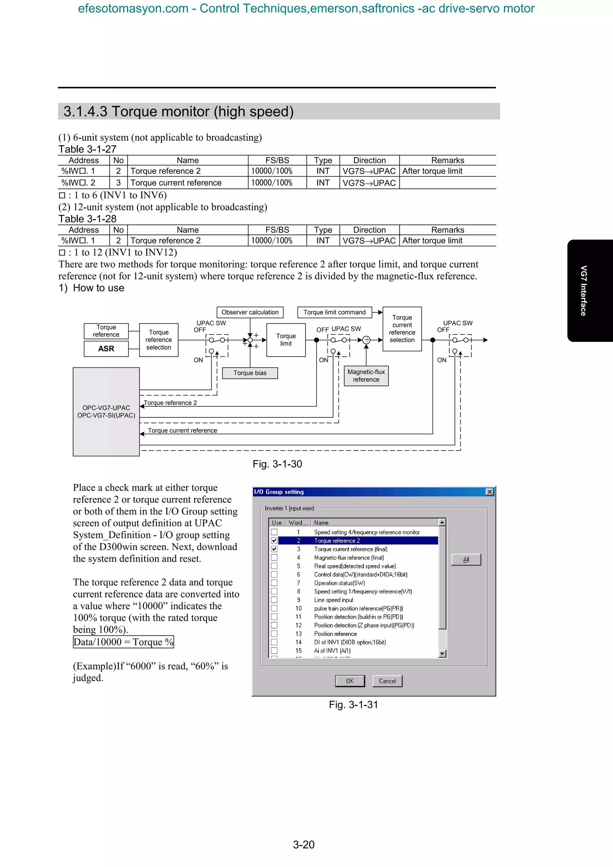
![3. VG7 Interface
3-21
3.1.4.4 Status monitor (high speed)
(1) 6-unit system (not applicable to broadcasting)
Table 3-1-29
Address No Name FS/BS Type Direction Remarks
%IW¨. 5 6
Control data (CW)
(standard + DIOA, 16-bit)
Data type: 32 WORD VG7S→UPAC
%IW¨. 6 7 Operation status (SW) Data type: 21 WORD VG7S→UPAC
¨ : 1 to 6 (INV1 to INV6)
(2) 12-unit system (not applicable to broadcasting)
Table 3-1-30
Address No Name FS/BS Type Direction Remarks
%IW¨. 3 6
Control data (CW)
(standard + DIOA, 16-bit)
Data type: 32 WORD VG7S→UPAC
%IW¨. 4 7 Operation status (SW) Data type: 21 WORD VG7S→UPAC
¨ : 1 to 12 (INV1 to INV12)
The high-speed status monitor consists of control data ([FWD], [REV], [X1] to [X9], and [X11] to [X14])
and operation status.
1) How to use
To refer to the data, place a check mark in the
system definition, download the system
definition, and reset.
Place a check mark at the check box of the
corresponding data items in the I/O Group
setting screen of output definition at UPAC
System_Definition - I/O group setting of the
D300win screen.
Fig. 3-1-32
The control input and operation status data are referred to in word information. The data format is as
shown below.
Control data (CW), operation status
15 8 7 0
Control data (CW), type [32]. Operation status (SW), type [21]
0) [FWD] ・・・・・・・・・・・・・・・・・・・・・ FWD (forward operation)
1) [REV] ・・・・・・・・・・・・・・・・・・・・・ REV (reverse operation)
2) [X1] ・・・・・・・・・・・・・・・・・・・・・・・ EXT (DC braking, pre-exciting)
3) [X2] ・・・・・・・・・・・・・・・・・・・・・・・ INT (inverter shutoff)
4) [X3] ・・・・・・・・・・・・・・・・・・・・・・・ BRK (braking)
5) [X4] ・・・・・・・・・・・・・・・・・・・・・・・ NUV (DC link circuit voltage establishment)
6) [X5] ・・・・・・・・・・・・・・・・・・・・・・・ TL (torque limiting)
7) [X6] ・・・・・・・・・・・・・・・・・・・・・・・ VL (voltage limiting)
8) [X7] ・・・・・・・・・・・・・・・・・・・・・・・ IL (current limiting)
9) [X8] ・・・・・・・・・・・・・・・・・・・・・・・ ACC (accelerating)
10) [X9] ・・・・・・・・・・・・・・・・・・・・・・ DEC (decelerating)
11) [X11] ・・・・・・・・・・・・・・・・・・・・・ ALM (alarm)
12) [X12] ・・・・・・・・・・・・・・・・・・・・・ 0: remote/local, 1: COM
13) [X13] ・・・・・・・・・・・・・・・・・・・・・ –
14) [X14] ・・・・・・・・・・・・・・・・・・・・・ –
15) [RST](RESET command) ・・・ –
efesotomasyon.com - Control Techniques,emerson,saftronics -ac drive-servo motor](https://image.slidesharecdn.com/vg7upacmanual-140613044924-phpapp01/75/Vg7-upac-manual-115-2048.jpg)
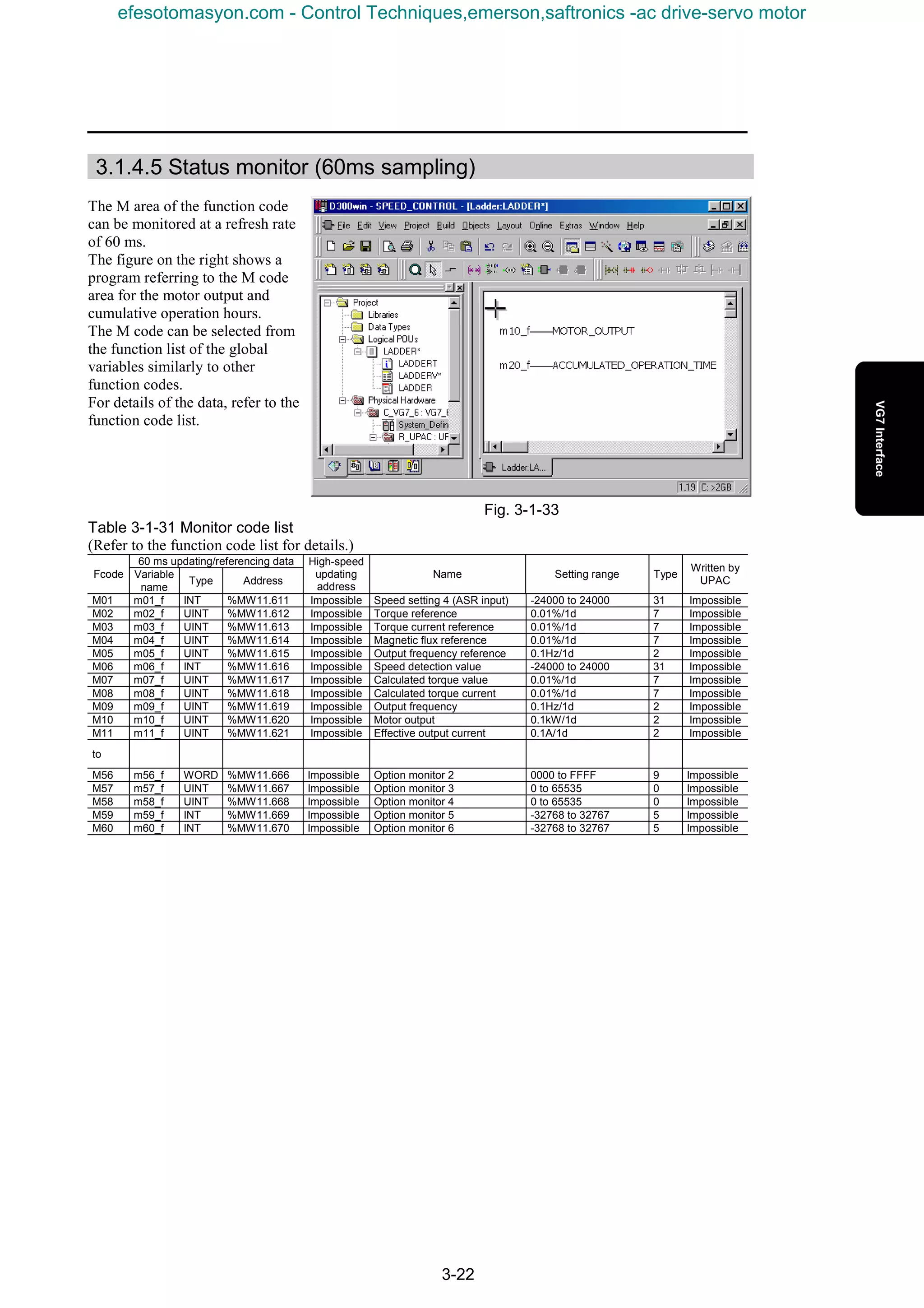
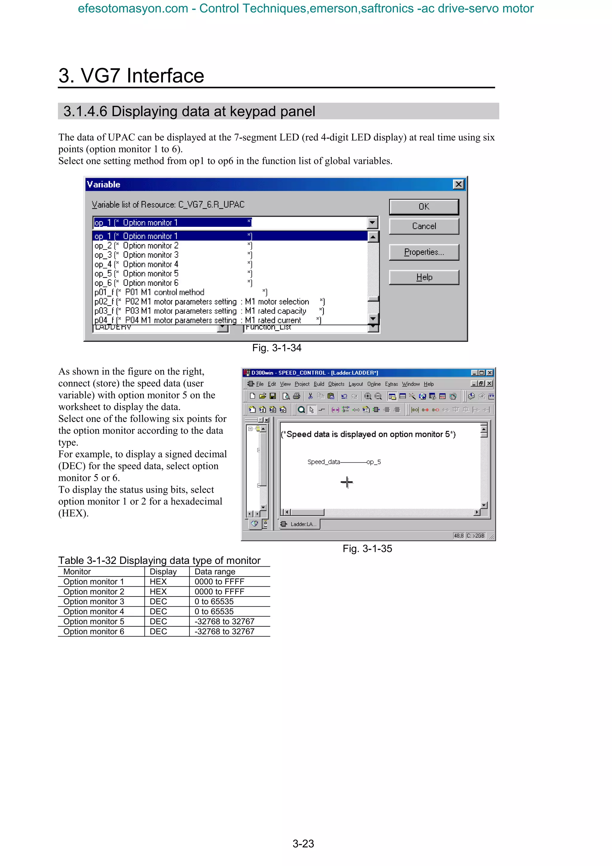
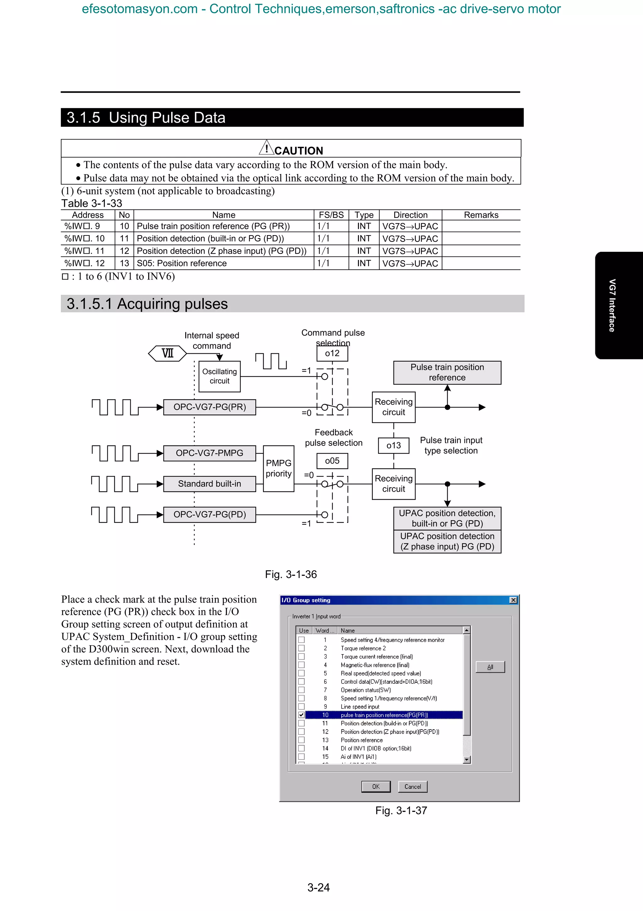
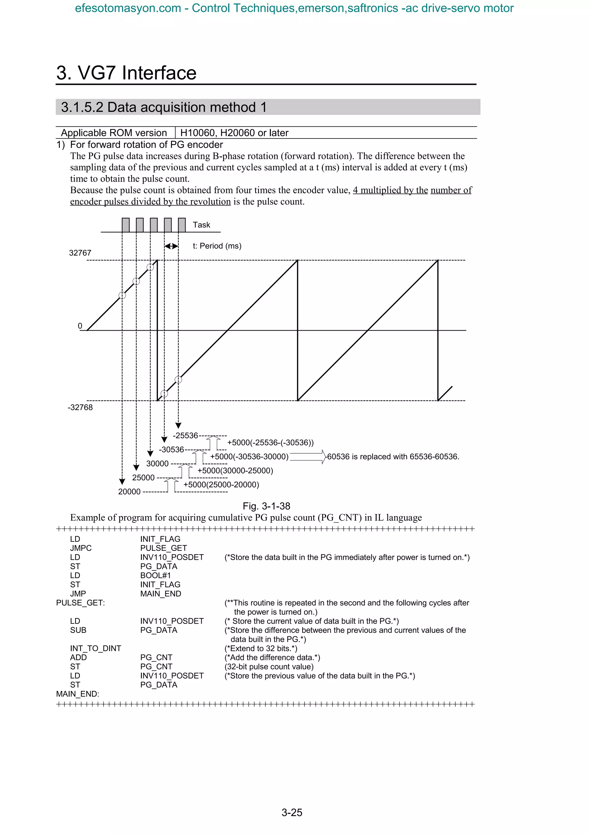
![3-26
[Concrete example with values]
Suppose that the motor equipped with a 1024 P/R encoder rotates at 60 r/min. If the above task takes 1
ms, each piece of memory data is counted as follows.
PG_CNT=00000000→00004096(32bit)
PG_DATA = 0004 or 0005 (during rotation), or 0000 when stopped
[Speed calculation example]
When the difference data (PG_DATA) sampled at 100 ms intervals is +5000 pulses, the speed of the
rotor (motor, mechanical shaft, or line) to which the PG (1024 P/R) is connected, is calculated to be 732
r/min in the following equation.
Speed of rotor (r/min)
[Example of calculation of winding diameter]
Acquire data from the PG installed to the winding shaft. When the line speed is 100 m/min and the
difference data (PG_DATA) sampled at 100 ms intervals is +5000 pulses, the winding diameter of the
winding shaft to which the PG (1024 P/R) is connected, is calculated to be 21.7 cm in the following
equation.
Winding diameter (m)
2) For reverse rotation of PG encoder
The PG pulse data decreases during A-phase rotation (reverse rotation). The difference between the
sampling data of the previous and current cycles sampled at a t (ms) interval is added at every t (ms)
time to obtain the pulse count.
Because the pulse count is obtained from four times the encoder value, 4 multiplied by the number of
encoder pulses divided by the revolution is the pulse count.
Fig. 3-1-39
min)/(4.732
min)/(60)/1(
)(100
)/(1000
)/(
10244
1
)(5000)
r
ss
ms
sms
prp
=
××
×
×+=
)(0217.0
(min)
4.7322
1
min)/(100
m
m
=
×
×=
π
32767
-32768
0
-20000
-25000
-30000
30536
25536
-5000(-25000+20000)
60536 is replaced with 60536-65536.-5000(30536+30000)
-5000(25536-30536)
Task
-5000(-30000+25000)
t: Period (ms)
efesotomasyon.com - Control Techniques,emerson,saftronics -ac drive-servo motor](https://image.slidesharecdn.com/vg7upacmanual-140613044924-phpapp01/75/Vg7-upac-manual-120-2048.jpg)
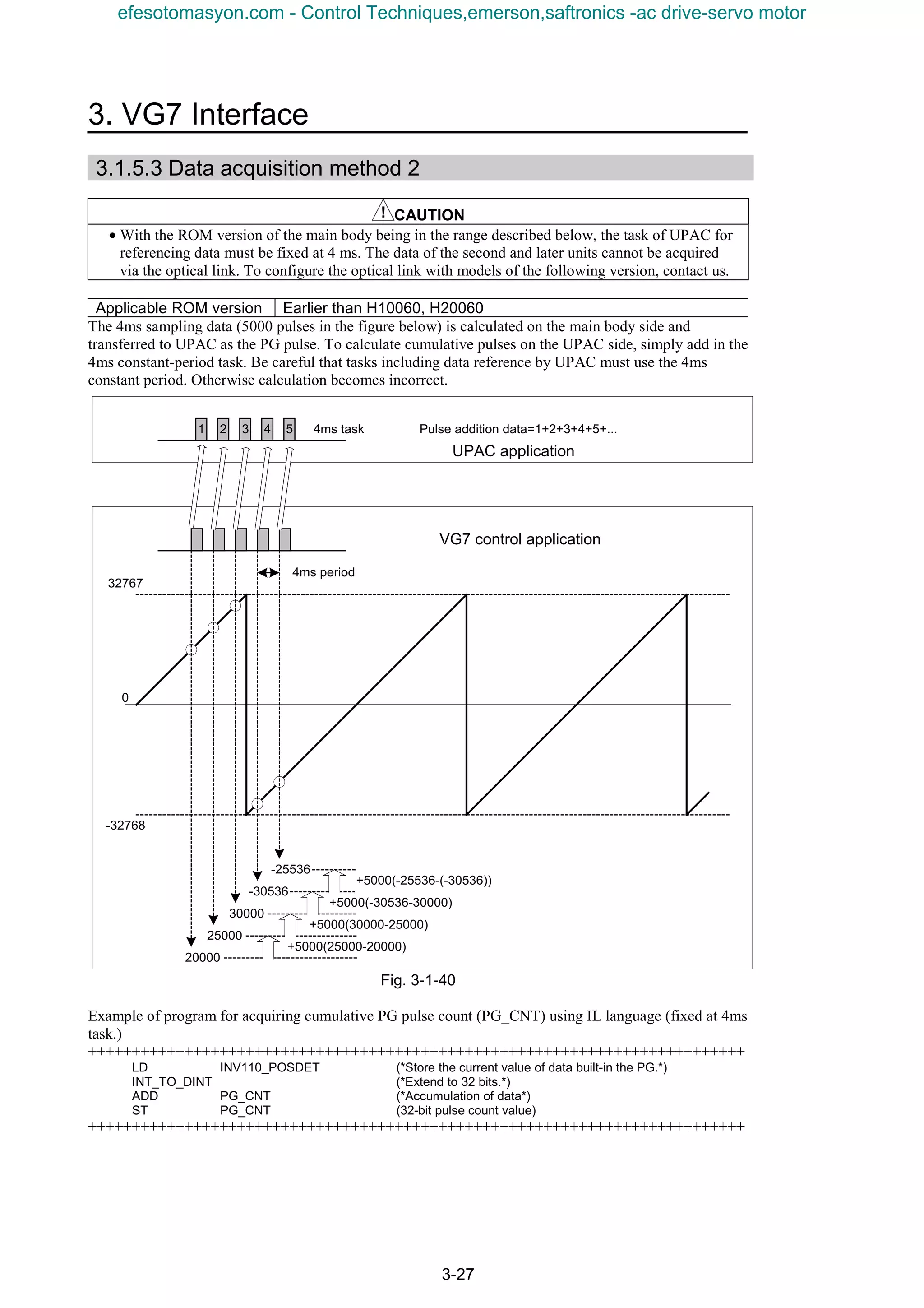
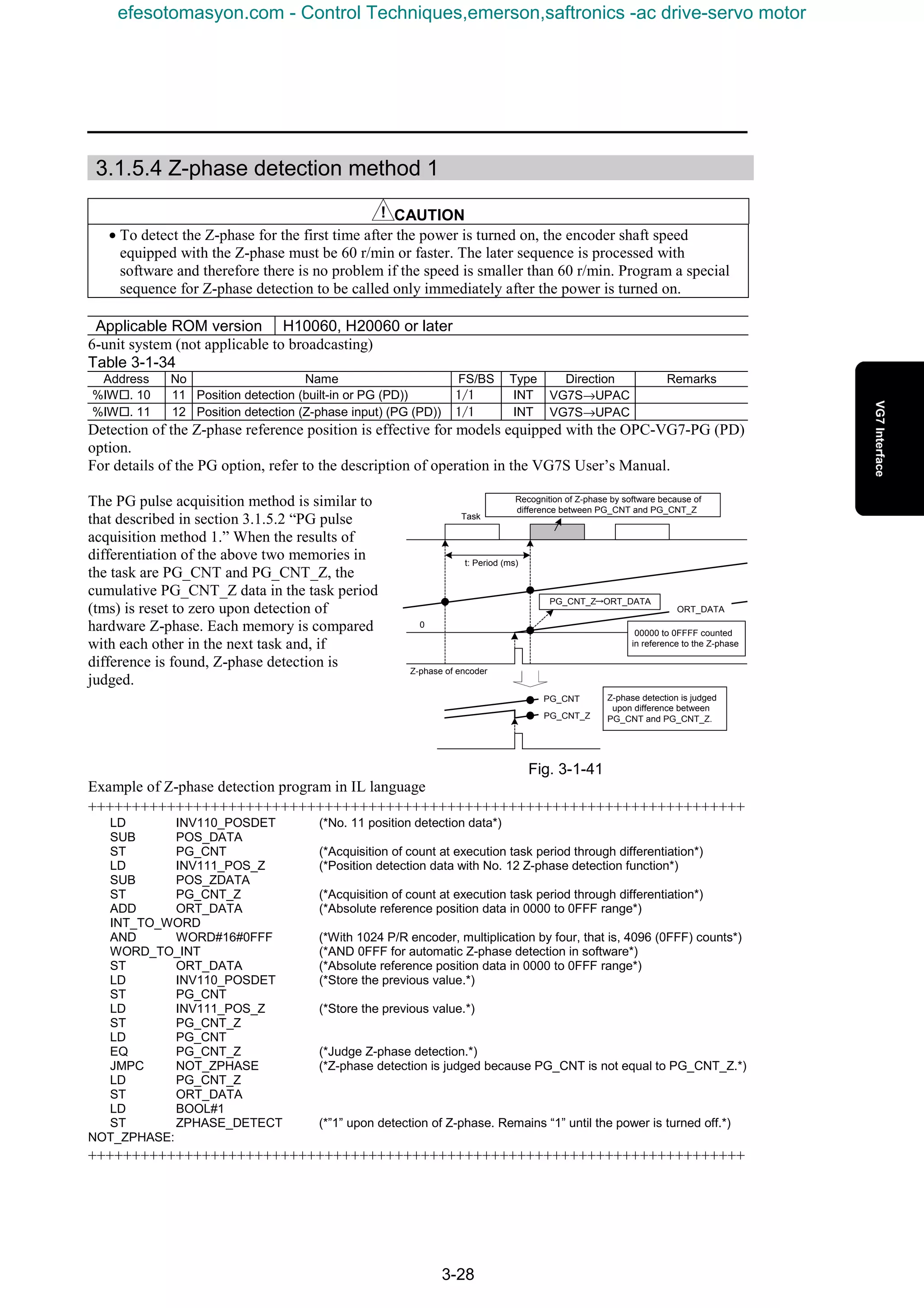
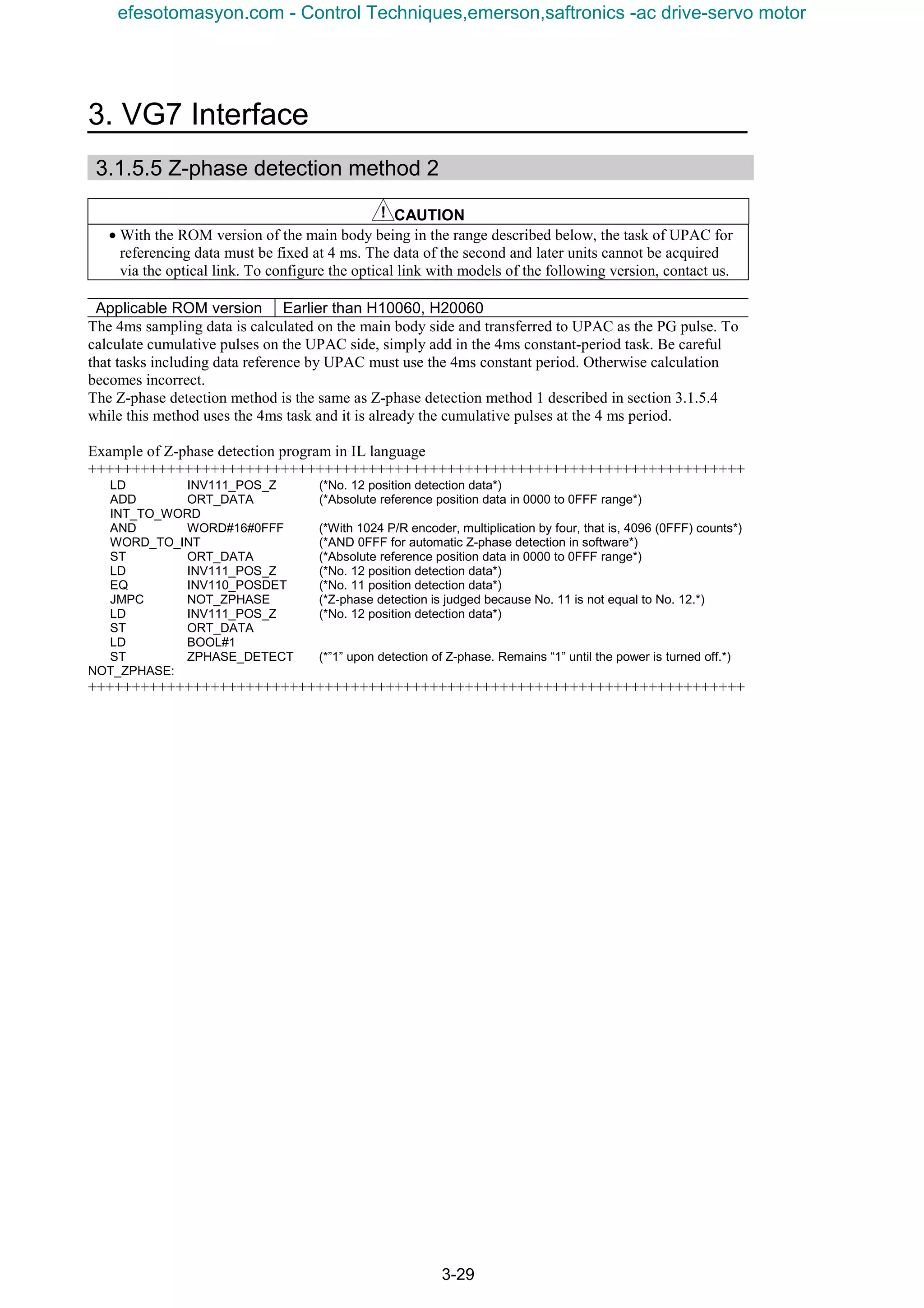
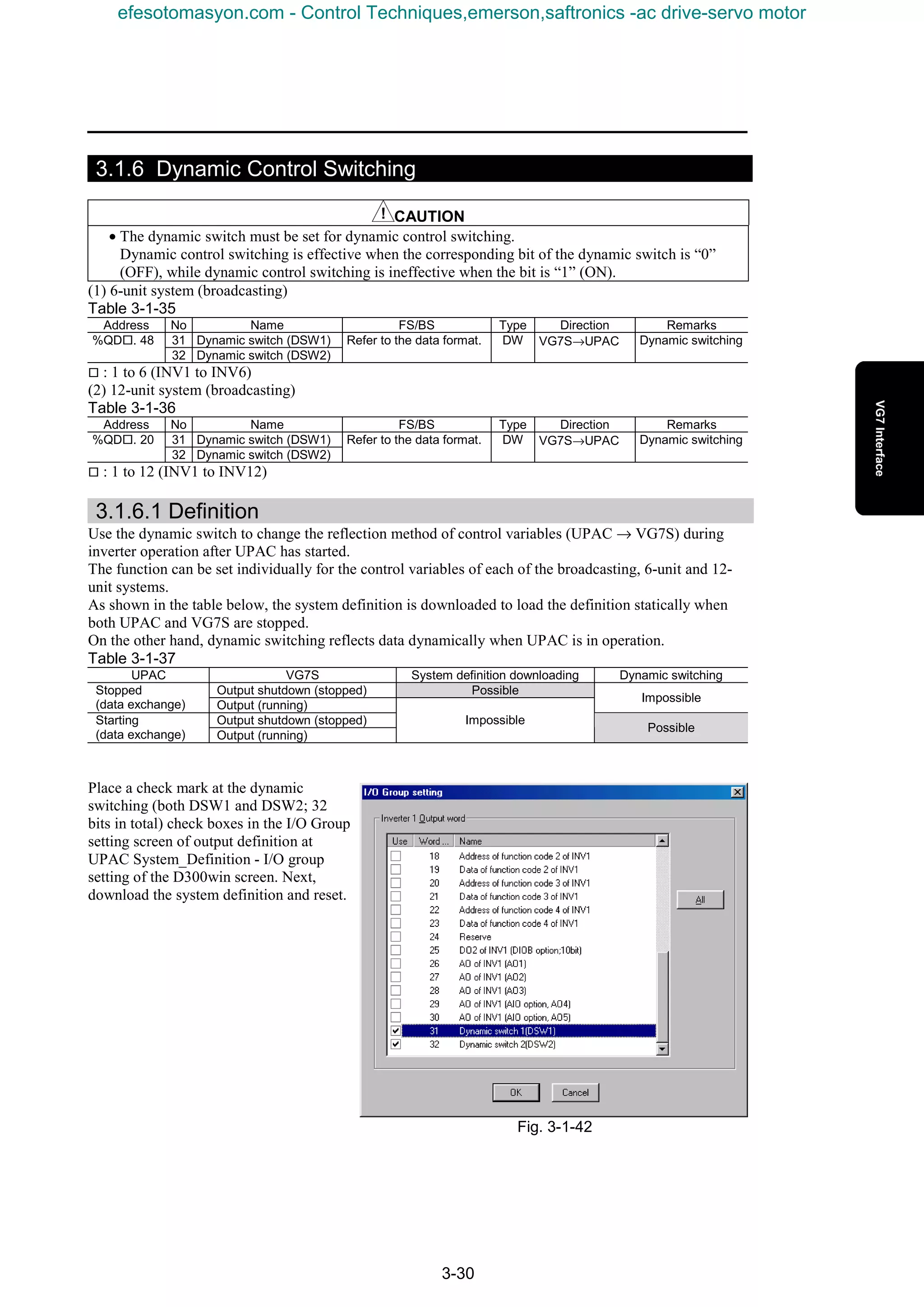
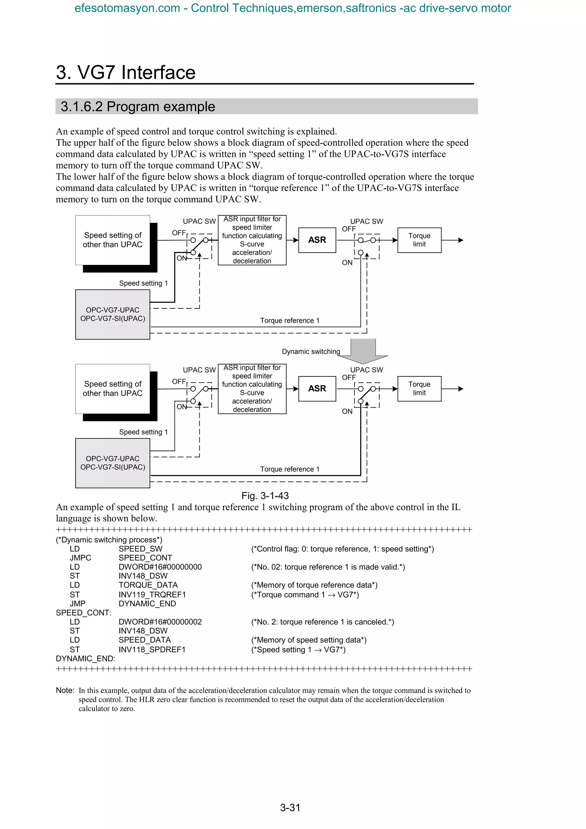
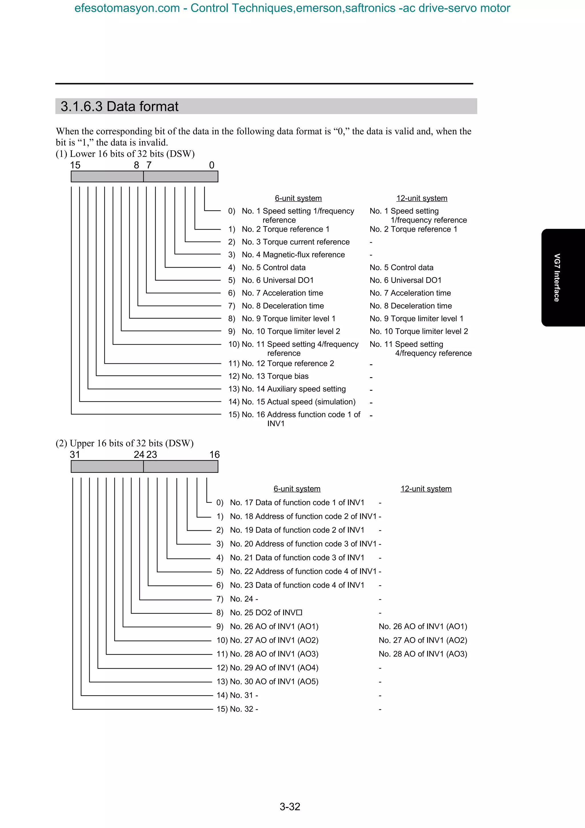
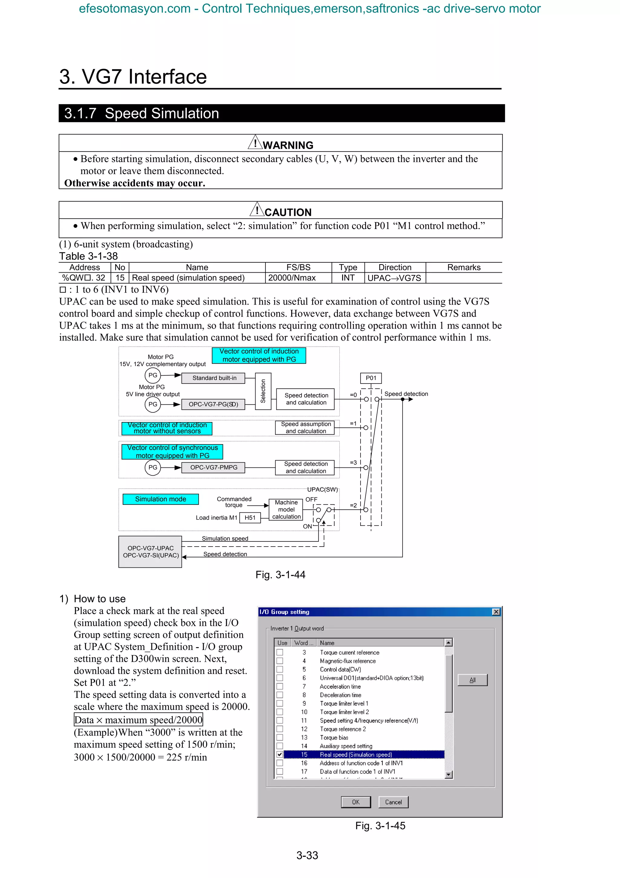
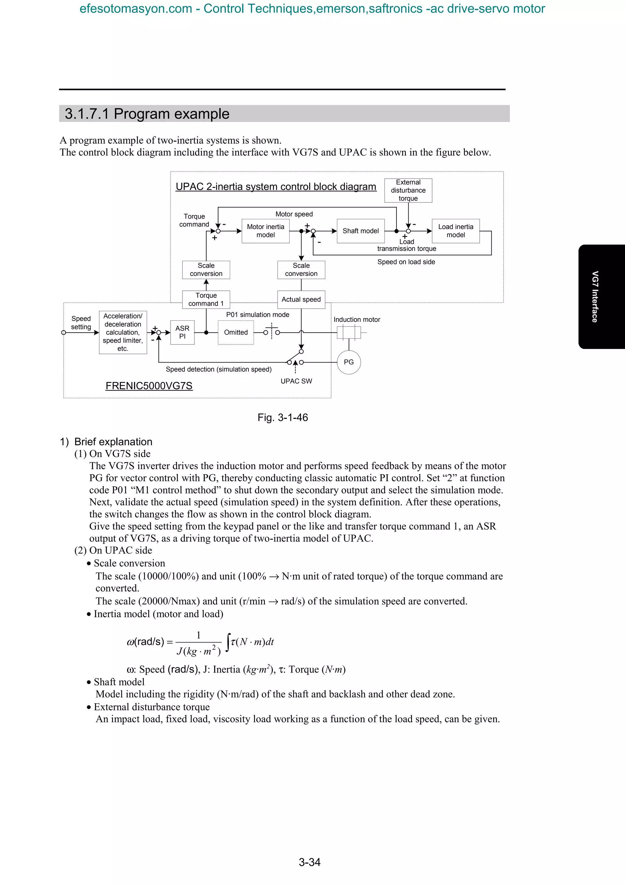
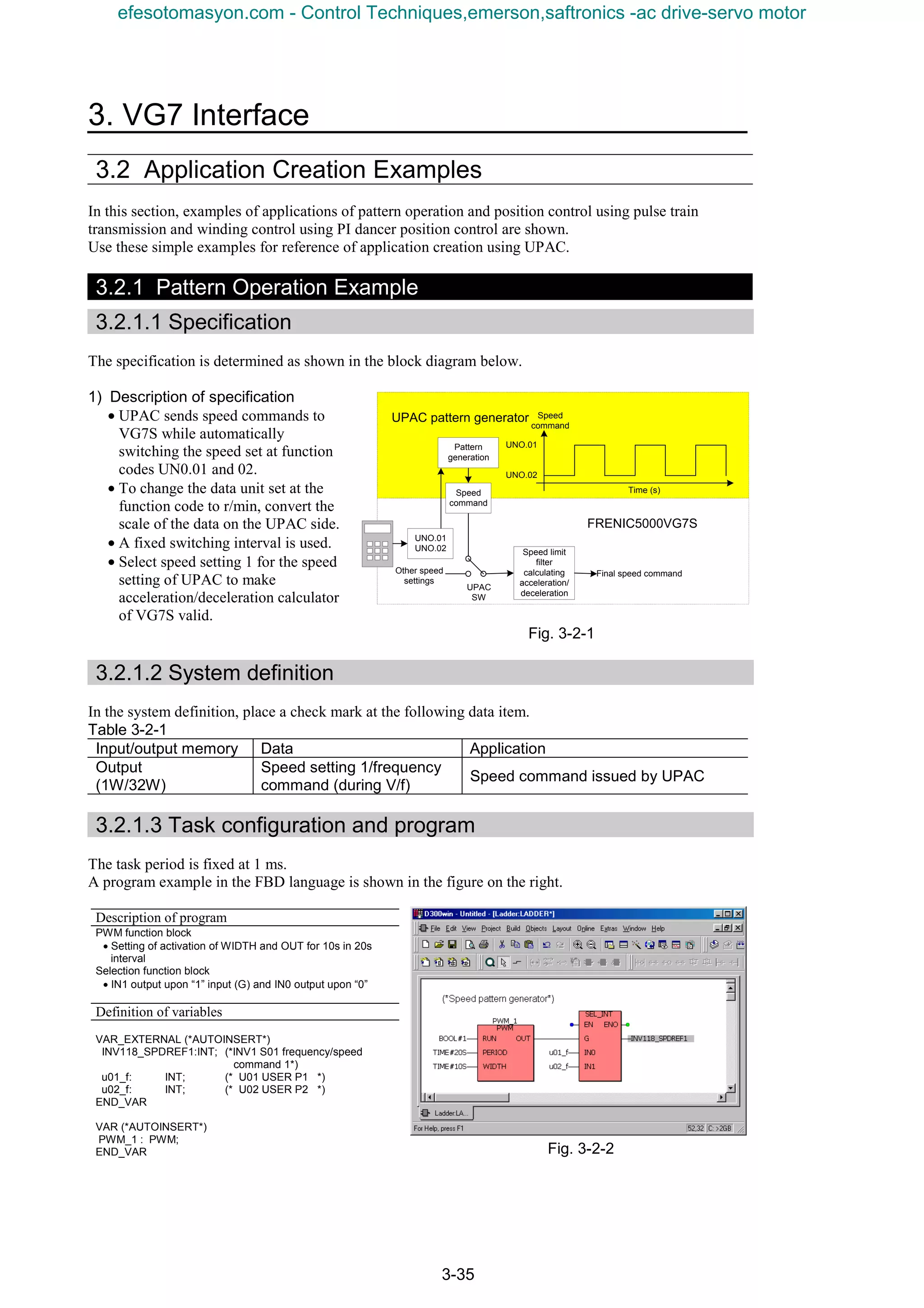
![3-36
3.2.2 Position Control Example Using Pulse train
An example of simple position control program in the IL language using a pulse train reference is
introduced.
3.2.2.1 Specification
The specification is determined as shown in the control block diagram below.
Fig. 3-2-3
1) Description of specification
• The pulse train reference issued by the pulse generator is received at the OPC-VG7-PG (o) option
and sent to UPAC as a pulse reference. (Variable: pulse string position reference PG (PR))
• The speed feedback data of the encoder installed to the induction motor, is sent to UPAC as detected
pulses. (Variable: position detection (built-in)
• The cumulative count multiplied by APR (position control) gain is handed over to VG7S as a speed
command so that the cumulative deviation between the command and detection becomes zero.
(Variable: speed setting 4/frequency reference (during V/f)
(Note: The stationary deviation does not become zero with APR gain only. It becomes zero during stoppage.)
• VG7S dynamically switches between validation and cancellation (validation of internal speed
setting) of the speed command sent from UPAC, using the [X1] input.
• When the speed setting of UPAC is effective, the internal data of the internal acceleration/
deceleration calculator is reset to zero. (Variable: control data)
• The APR gain is assigned to UN0.01 so that it can be changed or referred to from the keypad panel.
• The definition of the APR gain for “1.0” (“10” in UN0.01 is assumed to be “1.0”) is assumed to be
one speed unit (with “20000” speed units being the maximum speed) for a deviation of one pulse
train. That is, with a difference of 1000 pulses, 1000 speed units. When the maximum speed is 1500
r/min, the speed command is: 1500 × 1000/20000 = 75 r/min.
3.2.2.2 System definition
A check mark is placed for the following data items.
Table 3-2-2
Input/output
memory
Data Application
Control data (CW) (standard + DIOA option, 16-bit) Monitoring of [X1] input state
Pulse train position reference (PG (PR)) Acquisition of pulse train position reference
Input
(3W/18W)
Position detection (built-in or PG (PD)) Acquisition of pulse train position detection
Control data (CW) Issuance of ACC/DEC zero clear command
Speed setting 4/frequency reference (during V/f) Speed command from UPAC
Dynamic switch (DSW1)
Output
(4W/32W)
Dynamic switch (DSW2)
Dynamic switch between speed command from
UPAC and internal speed command
ASR
PI
Omitted
PG
UPAC position control block diagram
Speed
detection
Speed
setting +
-UPAC
SW
Induction motorSpeed limit
filter
calculating
acceleration/
deceleration
FRENIC5000VG7SPulse
generator
OPC-VG7-PG(o)
Pulse
command
Pulse
detection
+
-
Accumul
ation
process
APR
gain
Speed
command
Control
switch
Standard
I/O
[X1]
Control
input
Dynamic
switch
Speed
detection
Limiting
process
UNO.01
Function
code
Control
command
ACC/DEC
zero clear
efesotomasyon.com - Control Techniques,emerson,saftronics -ac drive-servo motor](https://image.slidesharecdn.com/vg7upacmanual-140613044924-phpapp01/75/Vg7-upac-manual-130-2048.jpg)
![3. VG7 Interface
3-37
3.2.2.3 Task configuration and program
Select a constant-period task of about 1 ms to 4 ms, considering the position control response and
acquisition and response of the control terminal [X1]. A program example in the IL language is shown
below.
The pulse string acquisition program is applicable to H10060 or H20060 or later ROM versions of the
main body.
If the version is earlier, refer to section 3.1.5 “Using Pulse Train Data” to change.
Program Variable definition (Definition of global variables)
(*START*) VAR_EXTERNAL (*AUTOINSERT*)
LD INV105_CW (*Control data: [X1] input state acquisition*)
SHR_WORD UINT#2 (*Move [X1] bit to the least significant position.*)
WORD_TO_BOOL
ST SYC (*Reflect [X1] input status to SYC.*)
(*Synchronous control routine*)
LD SYC
JMPCN SPEED_OP (*Synchronization when [x1] is ON, clearing
process when OFF*)
(*Store first data.*)
LD SYC_FLG (*Store first data immediately after the power is
turned on.*)
JMPC PULSE_START
LD BOOL#1
ST SYC_FLG
LD INV109_PLSPOSREF (*Store previous PG_PR command data.*)
ST PR_DATA
LD INV110_POSDET (*Store previous PG_ built-in data.*)
ST PG_DATA
JMP MAIN_END
PULSE_START:
(*Latch position command data.*)
LD INV109_PLSPOSREF (*PG_PR command data*)
INV105_CW :WORD;
INV109_PLSPOSREF:INT;
INV110_POSDET :INT;
INV122_CW :WORD;
INV128_SPDREF4
:INT;
INV148_DSW :DWORD;
e10_f :UINT;
u01_f :INT;
(*User definition variable*)
SYC
SYC_FLG
PR_CNT
PG_CNT
DEV_CNT
PR_DATA
PG_DATA
APR_REAL
APR_OUT_REAL
APR_OUT_SPEED
(*INV1 M13 control data (CW)
(standard + DIOA; 16-bit) *)
(*INV1 pulse train position reference (PG (PR))*)
(*INV1 position detection (built-in or PG (PD)) *)
(*INV1 S06 control data (CW) *)
(*INV1 speed setting 4/frequency reference
(during V/f) *)
(*INV1 dynamic switch *)
(*E10 X11 function selection *)
(*U01 USER P1 *)
: BOOL;
: BOOL;
: DINT;
: DINT;
: DINT;
: INT;
: INT;
: REAL;
: REAL;
: INT;
SUB PR_DATA
INT_TO_DINT (*Extension to 32 bits*)
ADD PR_CNT
ST PR_CNT
LD INV109_PLSPOSREF (*Store previous PG_PR command data.*)
ST PR_DATA
(*Latch position detection data.*)
LD INV110_POSDET (*PG_ built-in data*)
END_VAR
SUB PG_DATA
INT_TO_DINT (*Extension to 32 bits*)
ADD PG_CNT
ST PG_CNT
LD INV110_POSDET (*Store previous PG_ built-in data.*)
ST PG_DATA
(*Position deviation calculation*)
LD PR_CNT
SUB PG_CNT
ST DEV_CNT (*Position deviation = command data - detection data*)
(*APR output calculation*)
LD u01_f (*Assign position control gain to UNO.01.*)
INT_TO_REAL (*Convert to 32-bit floating point for preparation.*)
ST APR_REAL
LD DEV_CNT
DINT_TO_REAL (*Convert to 32-bit floating point for preparation.*)
MUL APR_REAL
MUL REAL#0.1 (*Multiply APR gain scale by 0.1.*)
ST APR_OUT_REAL
LD REAL#-20000.0 (*Limit to -20000 to 20000 range.*)
LIMIT_REAL APR_OUT_REAL , REAL#20000.0
REAL_TO_INT
ST APR_OUT_SPEED (*APR output*)
(*Dynamic switching*)
LD DWORD#16#00000000 (*Validate No. 11 speed setting 4.*)
ST INV148_DSW
LD WORD#16#0803 (*ACC/DEC zero clear function: [X11] = ON*)
ST INV122_CW
LD APR_OUT_SPEED
ST INV128_SPDREF4 (*Send speed data to VG7S.*)
JMP MAIN_END
SPEED_OP: (*Speed control operation routine.*)
(*Dynamic switching*)
LD DWORD#16#00000400 (*Cancel No. 11 speed setting 4.*)
ST INV148_DSW
LD WORD#16#0003 (*ACC/DEC zero clear function: [X11] = OFF*)
ST INV122_CW
(*Memory clearing process*)
LD DINT#0
ST PR_CNT (*Command data count clear*)
ST PG_CNT (*Detection data count clear*)
ST DEV_CNT
LD REAL#0.0
ST APR_OUT_REAL
LD INT#0
ST APR_OUT_SPEED
ST PR_DATA
ST PG_DATA
LD BOOL#0
ST SYC_FLG
MAIN_END:
LD UINT#15 (*Assign ACC/DEC zero clear function.*)
ST e10_f (*Assign above function to [X11].*)
efesotomasyon.com - Control Techniques,emerson,saftronics -ac drive-servo motor](https://image.slidesharecdn.com/vg7upacmanual-140613044924-phpapp01/75/Vg7-upac-manual-131-2048.jpg)
![3-38
3.2.3 Example of Dancer Control
3.2.3.1 Specification
The specification is determined as shown in the control block diagram below.
Fig. 3-2-4
1) Description of specification
• The analog line speed of the sender is input to [Ai2] of the driving VG7S of the sender and
transferred to UPAC. At this time, the function selection of AI2 is set at universal Ai.
• The analog position of the dancer is detected and input to [Ai1] of the driving VG7S of the sender
and transferred to UPAC. At this time, the function selection of AI2 is set at universal Ai.
• UPAC takes PI control based on the dancer position command (UNO.03) so that the difference with
the dancer position becomes zero, where the PI output is added to the line speed for a speed setting
transferred to VG7S. (Variable: speed setting 4/frequency reference (during V/f))
• The PI constant of the PI controller is assigned to function codes UNO.01 and 02 of the keypad
panel.
• The operation state of the inverter is checked at a constant period of 60 ms, using the INT signal (bit
3 of function code M14, inverter shutoff: %MW11.624.3), and the output of the integration term is
reset to zero during inverter shutoff (with INT signal being turned on).
3.2.3.2 System definition
A check mark is placed in the following data items of the system definition.
Table 3-2-3
Input/output
memory
Data Application
INV1 Ai(Ai1) Analog dancer position detectionInput
(2W/18W) INV1 Ai(Ai2) Analog line speed command
Output
(1W/32W)
Speed setting 4/frequency reference (during V/f) Speed command from UPAC
UPAC dancer control block diagram
Speed limit filter
calculating
acceleration/
deceleration
FRENIC5000VG7S
Position
command
Dancer
position
+
-
PI
control
Speed
command
Standard
I/O[Ai1]
Control input
Limiting
process
UNO.01: P gain
UNO.02: Constant
UNO.03: Position
command
%MW11.624.3
Function code
[Ai2]
Other speed
settingsa
M M
Sending
side
Winding sideWinding sideWinding sideWinding side
Winding side
speed
command
Line speed
Dancer position detection
UPAC
SW
Line speed
+ +
Integration
item zero
clear
efesotomasyon.com - Control Techniques,emerson,saftronics -ac drive-servo motor](https://image.slidesharecdn.com/vg7upacmanual-140613044924-phpapp01/75/Vg7-upac-manual-132-2048.jpg)
![3-40
3.3 VG7S Control Block Diagrams
3.3.1 Operation Command
(FWD)
Serial
link
UPACSW
H30
=0,1
=2,3
Operation
selection
through link
F02
Operation
method
=1
KEYPAD
panel=0
Forward
rotation
command
ON
OFF
[FWD]
FWD
Terminalblock
OPC-VG7-TL
OPC-VG7-SX
Fieldbus
Option
cards
ForwardrotationcommandfromUPAC
Fixedpriority
(REV)
=0,1
=2,3
F02
Operation
method
=1
KEYPAD
panel=0
ON
OFF
REV
Terminalblock
ReverserotationcommandfromUPAC
Reverse
rotation
command
Commands
are
disconnected
whenturned
on
simultaneously
IfyouenterFWDandREVcommandssimultaneously,commandswillbecancelledandthemotor
willdeceleratetostop.
-OnlyonefieldoptionisselectablefromTL,SX,orfieldbus.
-IfanXterminaldoesnotassigntheoperationselectionthroughlink[LE],"ON"isassumedtoit.
-Commandsrelatedtolinkoperationhavethefollowingpriority.UsefunctionS06foran
operationcommand.
(a)RSoption
(b)TL,SX,andfieldbus
(c)IntegratedRS485
-CommandsfromtheUPACorSIoptionwillbeANDedwithothercommands.
OPC-VG7-UPAC
OPC-VG7-SI(UPAC)
OPC-VG7-TL
OPC-VG7-SX
Fieldbus
Option
cards
Integrated
RS485
OPC-VG7-UPAC
OPC-VG7-SI(UPAC)
Fixedpriority
1
2
3
1
2
3
OFF
ON
OFF
ON
S06
S06
COM(link)
REMOTE
LOCAL
COM(link)
LOCAL
REMOTE
OPC-VG7-RS
OPC-VG7-RS
AND
AND
AND
24 [ LE]
Statesofall
switchesindicate
factorysetting.
KEYPADpanel
RUN/STOP
I/Ocheck
Monitor
M14
Operation
status
3-wire operation
stop command
6 [ HLD]
Hold
HoldSTOP1,2,3
52 [ STOP1]
53 [ STOP2]
54 [ STOP3]
[REV]
Integrated
RS485
efesotomasyon.com - Control Techniques,emerson,saftronics -ac drive-servo motor](https://image.slidesharecdn.com/vg7upacmanual-140613044924-phpapp01/75/Vg7-upac-manual-134-2048.jpg)
![3. VG7 Interface
3-41
3.3.2 Speed Command Selection Section
UP/DOWN
initialvalue:
zero
UP/DOWN
Initialvalue
Previous
value
UP/DOWN
Initialvalue
Creep
=1*
=0*
=*1
=*0
Creepspeedselect
KEYPADpanel
speedsetting
=0
=1
=2
=3
=4
=5
=6
=1,3
=0,2
H30
C05
C06
C07
C08
C09
C10
C11
C12
C13
C14
C15
C16
C17
C18
C19
C21
Agreement
timer
C20
Multistepspeedsettingmethod
Agreement
timertime:
Multistep speed
selection
Speed auxiliary
setting 1
×
Speed override
+
+
C25
=0,3,4,5
=1,2,6,7
C29Joggingspeed
command
Jump
speed
C01
C02
C03
C04
(0to±10V)
(0to+10V)
=7
Creepspeedselect
Creepspeed1
Creepspeed2
Seriallink
Operation
selection
through link
I
Jumpspeed1
Jumpspeed2
Jumpspeed3
Jumphysteresis
widthKEYPAD
operation
Jogging
operation
F01
Speedcommand
N1
Speedcommand
N2
[PIDOUT]
PIDcalculation
output
0
PIDreference
value
C73
ON
OFF
∨∨∨∨
∧∧∧∧FUNC
DATA
OPC-VG7-TL
OPC-VG7-SX
Fieldbus
Optioncards
Speedsetting1fromUPAC
IntegratedRS485
Fixedpriority
1
2
3
OPC-VG7-DIA
OPC-VG7-DIB
Optioncards
UPACSW
-Theterminal[N2/N1]switchesF01andC25,whichspecifythesubjectofthe
speedcontrol.
-ThePIDcalculationoutput[PIDOUT]isinternallycalculatedvalue.SeethePID
controlblock.
-TheUP/DOWNfunctionortheKEYPADspeedsettingwillcancel"Auxiliaryspeed
setting1"and"Speedoverride".
C25
F01
Speed
commandN1
Speed
commandN2
OFF
ON
REMOTE
COM
(LINK)
S01
OPC-VG7-RS
∧∧∧∧
OPC-VG7-UPAC
OPC-VG7-SI(UPAC)
Ai
Ai
OFF
ON
C19
C18
OR
STOP
Speed
reference
UP/DOWN
function
[DIA]
[DIB]
Ai
Ai
UPcommand
DOWNcommand
Statesofall
switchesindicate
factorysetting.
UPAC
(Speedsetting1)
11 [ N2/N1]
Speed setting
N1/speed
setting N2
Speed setting
N1/speed
setting N2
24 [ LE]
0 [ SS1]
1 [ SS2]
2 [ SS4]
3 [ SS8]
1 [ AUX-N1]
13 [ N-OR]
11 [ N2/N1]
10 [JOG]
17[UP]
18[DOWNN]
16[CRP-N2/N1]
8[CRP-N1]
9[CRP-N2]
Gain
F17
Bias
F18
+-[12]
H27
PIDcontrol
(Speedreference)
=1
=0
Multistep
speed1
Multistep
speed2
Multistep
speed3
Multistep
speed4
Multistep
speed5
Multistep
speed6
Multistep
speed7
Multistep
speed8
Multistep
speed9
Multistep
speed10
Multistep
speed11
Multistep
speed12
Multistep
speed13
Multistep
speed14
Multistep
speed15
Speedsetting1
M49
Speedsetting1
Monitor
×
efesotomasyon.com - Control Techniques,emerson,saftronics -ac drive-servo motor](https://image.slidesharecdn.com/vg7upacmanual-140613044924-phpapp01/75/Vg7-upac-manual-135-2048.jpg)
![3-42
3.3.3 Acceleration/Deceleration Calculation, Speed Limiting, and
Position Control Input Section
I
Forward
rotation
command
Reverse
rotation
command
-1
0r/min
F23
Starting
speed
Startingspeed
holdingtime
Upper
limiter
S-curve
acceleration/
deceleration
calculation
Bypass
ACC/DEC cleared to
zero command
KEYPAD
operation
Acceleration/
deceleration1Speed auxiliary
setting 2
+
+
Speed
limit
Speed reference
cancel
F76
F77
F78
Mode
selection
Controllevel1
Controllevel2
Inverse mode
change over
C38
C35
C36
C37
F70
F07
F08
F69
C49
C46
C47
C48
C59
C56
C57
C58
C69
C66
C67
C68
Acceleration/
deceleration
2
Acceleration/
deceleration
3
Acceleration/
deceleration
4
Acceleration/
deceleration
JOG
II
C25
F01
=0,3,4,5
F68
F67
Zero speed locking
command
Position
control
Position
detection
Hold
circuit
-
+
H55Gain
Speed
reference=0%
Zerospeedlocking
command
VII
Synchronization
command
Decelerateat
decelerationtime4
-1
+
+
PIDcalculationoutput
[PIDOUT]
H27
=2
+
+
PIDcontrol
(Speedreference)
M50
Speed
setting2
IV
Linearposition
control
Synchronizing
command
M51
Speedsetting3
Acceleration/deceleration
andS-curveswitching
Speedlimitin
speedcontrol
Monitor
Monitor
STOP
=1,2,6,7
SpeedcommandN1
SpeedcommandN2
OR
Ai
AND
Joggingoperation
ASR,ACC/DEC
timeselection
S08
S09
Acceleration/
deceleration
throughlink
2[N-REF2]
Speedsetting2
(Before
acceleration/
deceleration
calculation)
Statesofall
switchesindicate
factorysetting.
OPC-VG7-UPAC
OPC-VG7-SI(UPAC)
Accelerationtime/
decelerationtimeUPAC
SW
28 [ LOCK]
15 [ CLR]
36 [ BPS]
2 [ AUX-N2]
30 [ N-LIM]
27 [ SYC]
21 [ IVS]
F24
10[JOG]
53[STOP2]
4[RT1]
5[RT2]
Over
writing
Internal
speed
reference
ToASR
28[LOCK]
Operationcommand
blockdiagram
Zerospeed
lockingcommand
IX
Position
detection
OFF
ON
OFF
ON
I/Ocheck
PARA1,2,3,4
JOG
Monitor
UPACspeed
auxiliarysetting
COM(link)
-Positioncontrolfunctionhasthefollowingpriorities.
(a)Linearpositioncontrol(pulsetrainsynchronizedcontrol,optionalforOPC-VG7-PG)
(b)Simplifiedpositioncontrol(zerospeedlockingcontrol)
-YoucanuseboththeKEYPADpanelandthe[JOG]ontheterminalboxtoswitchtothejogging
mode.
-Thedisplayedvalueforthespeedcontrolistheonebeforetheacceleration/deceleration
calculation.
-TheCOM(link)systemisdisplayedas.WritingintoS08andS09doesnot
dependonH30and[LE].TheyalwaysoverwriteF07andF08.Whenyouusethelink,set
[RT1]and[RT2]toenable"Acceleration/deceleration1".
COM(link)
∧∧∧∧
efesotomasyon.com - Control Techniques,emerson,saftronics -ac drive-servo motor](https://image.slidesharecdn.com/vg7upacmanual-140613044924-phpapp01/75/Vg7-upac-manual-136-2048.jpg)
![3. VG7 Interface
3-43
3.3.4 Motor Speed/Line Speed Detection
Speeddetection
calculation
P28A32M1PGpulse
number
M2PGpulse
number
Machine
model
calculation
Torquereferencevalue
P01
M1control
method
A01
=0
=3
=1
H51M1loadinertia
H53
Analoglinespeed
detection
Linespeed
Feedback
selection
III
o06
o07
o08
P29
M1externalPG
correctioncoefficient
OPC-VG7-PG(SD)
OPC-VG7-PG(LD)
PG
MotorPG
15Vand12V
complementaryoutput
MotorPG
5Vlinedriveroutput
SDprioritization
Vectorcontrolforinduction
machinewithPG
OPC-VG7-PMPG
Digitallinespeed
detection
Vectorcontrolforsensorless
inductionmachine
Simulatedoperationmode
Vectorcontrolforsynchronized
machinewithPG
=2
LDdefinition(Encoderpulsenumber)
LDdefinition(Detectedpulsecorrection1)
LDdefinition(Detectedpulsecorrection2)
=0
Ai=1
=2
=3
-YoucanselectaswitchontheOPC-VG7-PGcardtoswitchbetweenmotor
speeddetectionandlinespeeddetection.
(a)PG(SD):Controlsspeedbydetectingpulsetraintocalculatespeed.
(b)PG(LD):Controlslinespeedbydetectingdigitallinespeed.
-ThespeeddetectionandspeedestimationareinvalidforV/fcontrol.Ifyou
selecttheM3motor,theinverterswitchestoV/fcontrol.
-WhenyouapplyananalogfrequencysuchasTGoutputaslinespeed,use
FUJI'sFVconverterboardtoconvertitintovoltageforAi[LINE-N]input.
-Thepulseoutput(dividercircuit)isequalmagnificationoutput.
I/Ocheck
SD
Monitor
[PA]
Standard
integration
MotorM2,M3
selection
KEYPADpanel
LEDmonitor
Linespeed
detectedvalue
Monitor
[N-FB1]
Speedestimation
calculation
Speeddetection
calculation
Speeddetection
calculation
M2control
method
=0
=0=1=1
F79
Motorselection
(M1,M2,M3)
[N-FB1+]
AOspeedometer
(One-waydeflection)
AOspeedometer
(Two-waydeflection)
AOlinespeed
detection
Statesofall
switchesindicate
factorysetting.
UPAC,SI
(Speed
detection1)
UPAC,SI
(Linespeed
input)
UPAC(SW)
5[LINE-N]
11[LINE-N]
12[M-CH2]
13[M-CH3]
OFF
ONUPAC(simulatedspeed)
[PB]
PG
Divider
circuit
E29
PG
[FA]
[FB]
1500
Digitalspeedometer
Pulseoutput
PGpulseoutput
selection
PG
Vectorcontrolforinduction
machinewithPG
(Linespeedcontrol)
I/Ocheck
LD
Monitor
MCA,OPC-VG7-FVTG
Speed
detection
LinePG
LineTG
="0"to"6"
M06
Speed
detection1
KEYPADpanel
LEDmonitor
Detectedspeed
display
Monitor
P01
=2
11112
±
±
efesotomasyon.com - Control Techniques,emerson,saftronics -ac drive-servo motor](https://image.slidesharecdn.com/vg7upacmanual-140613044924-phpapp01/75/Vg7-upac-manual-137-2048.jpg)
![3-44
3.3.5 Pulse Train Reference Input Section and Position Detection
Section
IVOPC-VG7-PG(PR)
OPC-VG7-PMPG
=1
=0
Position(pulsetrain)
detection
Synchronized(pulse
train)reference
Position
control
Deviation
counter
Reference
pulse
calculation
Feedback
pulse
calculation
o14
o15
Reference
pulsecorrection
Oscillation
circuit
o12
Receiver
circuit
=0
=1
+
-
o16
F/F
calculation
o17
APRgain
+
+
o05
o13
VII
Internalspeed
reference
Reference
pulseselection
Feedback
pulseselection
Receiver
circuit
Pulsetraininput
formselection
F/Fgain
-YoucanselectaswitchontheOPC-VG7-PGcardtoswitchbetweentwotypesofpulsereference/pulse
detection.
(a)PG(PR):Controlspositionandsynchronizationbyreceivingareferencepulsetrainforpulse
calculation.
(b)PG(PD):Controlspositionbydetectingpulsetrainforpulsecalculation.
-Youcanoutputeitherofthepulsereferencevalue,theconvertedpulseoutputfortheinternalspeed
reference,orthedetectedpulsevaluethroughtheintegrated[FA]and[FB]inthepulseoutputcircuit.
-Theinvertersendsreferenceordetectedpulsedatamagnifiedbyfourandaccumulatedinevery4mstothe
UPAC.TheUPACmustrun4ms-cycletask.
[PA]
[PB]
Standard
integration
Pulse
output
circuit
E29
PGpulseoutput
selection
[FA]
[FB]
Position/
synchronizationcontrol
Pulseoutput
UPAC,SI
(Position
reference)
UPAC,SI
(positiondetection.
detectedZ-phase)
Linearposition
control
Synchronized
operation
="7"or"9"
Pulse
output
circuit
E29
PGpulseoutput
selection
="8"
[FA]
[FB]
Pulseoutput
Statesofall
switchesindicate
factorysetting.
IX
Position
detection
I/Ocheck
PD
Monitor
OPC-VG7-PG(PD)
I/Ocheck
PR
Monitor
PMPG
prioritization
(P02=3)
efesotomasyon.com - Control Techniques,emerson,saftronics -ac drive-servo motor](https://image.slidesharecdn.com/vg7upacmanual-140613044924-phpapp01/75/Vg7-upac-manual-138-2048.jpg)
![3. VG7 Interface
3-45
3.3.6 Speed Control and Torque Reference Section
IIASR
H41
III
+
-
C70
ASRswitching
time
H28
+
Droopoperation
H46
Observer
calculation
M1
Observertype
selection
Torquereference
selection
Proportional
gain
=0
=1
=3
=4
=2
F/Fgain
[PIDOUT]
H41 "Torque
reference
selection" cancel
PIDcalculation
output
=5
[N-REF4]
ASRinputfilter
ASR-JOG
ASR1
ASR2
ASR3
ASR4
ASRdetection
filter
M2
-ASR(AutomaticSpeedRegulator)and
S-curveacceleration/decelerationfunctions
switchsimultaneously.
-Torquecontrolandtorquecurrentcontrolhold
theASRoutputtozero.
-Theobserverbecomesineffectivewhenyou
setthemotorselectiontoM3(V/fcontrol).
OFF
UPACSW
ON
OFF
UPACSW
ON
OPC-VG7-RS
Integrated
RS485
Fixedpriority
1
2
3
OPC-VG7-DIB
OPC-VG7-DIA
Optioncards
ASR:Speedcontrol
system
V
F46
Mechanicalloss
compensation
value
F47
F48
F49
Torquebias
T3
+
+
+
+
+
Aitorque
biashold
0%
F50Activationtimer
-1
Rotation
direction
=1,2
Loaddisturbance/
vibrationsuppressing
observer
Torquebias
Seriallink
H30
=0,2
=1,3
Operation
selection
through link
ON
OFF
COM(link)
-
+
+
REMOTE
OPC-VG7-SI(UPAC)
OPC-VG7-TL
OPC-VG7-SX
fieldbus
KEYPAD
panel
operationSTOP
F79
Motorselection
(M1,M2,orM3)
Compensation
gain
Integration
timeLoad
inertia
H51H49H47
H52H50H48
=0
=1
=0,1
OR
Pgain
F61F62F63F64F65
C30C31C32C33
C44C40C41C42C43
C54C50C51C52C53
C64C60C61C62C63
Constant
of
integration
FFgainInput
filter
Detection
filter
Ai
Torquebias
T2
Torquebias
T1
Speedsetting4
Ai torque bias
Torque bias
reference 1/2
Torque
reference
Droop
selection
ASR,ACC/DEC
timeselection
MotorM2/M3
selection
Ai torque bias hold
[N-FB2]
AOspeedsetting4(ASRinput)
AOspeeddetection2
(ASRinput)
Statesofall
switchesindicate
factorysetting.
UPAC,SI
(Speedsetting4)
UPAC,SI
(Torque
reference1)
S02
24 [LE]
6[T-REF]
39[DROOP]
10[JOG]
4[RT1]
5[RT2]
12[M-CH2]
13[M-CH3]
31 [ H41-CCL]
37 [ TB1]
38 [ TB2]
51 [ H-TB]
5 [ TB-REF]
UPAC,SI
(Torquebias)
OFF
UPACSW
ON
+
Speed
detection
Speed
reference
Totorque
limitation
M01
Speed
setting4
Monitor
+
+
∧∧∧∧
±
×
efesotomasyon.com - Control Techniques,emerson,saftronics -ac drive-servo motor](https://image.slidesharecdn.com/vg7upacmanual-140613044924-phpapp01/75/Vg7-upac-manual-139-2048.jpg)
![3-46
3.3.7 Torque Limit, Torque Current Reference, and Magnetic-flux
Reference Section
V
Torque
limiter
F4032 [H42-CCL]
N
φ
III
Speed
detection
Magnetic-flux
reference
selection
=0
=1
=2
H43"Magnetic-fluxreference"canceling
H44
F73
Magnetic-flux
levelatlight
load
ASRoutput
filter
Torquecurrent
reference
Magnetic-flux
reference
Magnetic-flux
referencevalue
F41
Torquelimitermode1
Torquelimitermode2
H42 "Torque current command" canceling
Torquelimiter(level1,
level2selection)
F40"Torquelimitermode1"canceling
UPACtorque
limitervalue1
UPACSW
UPACSW
F42
3[TL-REF1]
Torquelimitervalue
(level1)selection
=1
=3
=4
=2
S10
=0F44
Torque
limitervalue
(level1)
=5
[PIDOUT]
PIDcalculation
output
F43
Torquelimitervalue
(level2)selection
S11
F45
Torque
limitervalue
(level2)
[PIDOUT]
PIDcalculation
output
DIB
DIA
UPACSW
UPACtorque
limitervalue2
OPC-VG7-DIA,DIB
OPC-VG7-UPAC
OPC-VG7-S(UPAC)
OFF
ON
ONONOFF
UPACSW
UPACSW
H42
Torquecurrent
referenceselection
=1
=3
=4
=2
S03
=0
ON
COM(link)
REMOTE
REMOTE
DIB
DIA
OFF
C34
C65
C55
C45
F66
ASR
outputfilter
ASR-JOG
ASR1
ASR2
ASR3
ASR4
=3S04COM(link)
-TheCOM(link)systemisabbreviatedas.NotethatitdependsonH30and[LE]asdescribeolin4.2.6.
Magnetic-flux
reference
KEYPAD panel
operation
STOP
VI
VIII
COM(link)
[DIB] [DIA]
ASR, ACC/DEC
time selection
Jogging operation
OR
S03
COM(link)
AOtorqueammeter
(one-waydeflection)
AOtorqueammeter
(two-waydeflection)
9[T-REF+]
8[T-REF]
AOtorquemeter
(two-waydeflection)
AOtorquemeter
(one-waydeflection)
Statesofall
switchesindicate
factorysetting.
ON
OFF
Polarity
selection
F51
Torquereference
monitor
UPAC,SI
(Torque
reference2)
UPAC,SI
(Torque
reference2)
UPAC,SI
(Torquecurrent
reference)
UPAC,SI
(Magnetic-flux
reference)
10 [JOG]
4 [RT1]
5 [RT2]
6[IT-REF]
7[IT-REF+]
4[TL-REF2]7[IT-REF]
35[TL2/TL1]
34[F40-CCL]
10[MF-REF]
33[H43-CCL]
Fixedfilter
UPAC,SI
(Torquecurrent
reference)
H43
UPAC,SI
(Magnetic-flux
reference)
Polarity
selectionF51
Torque
reference
monitor
M02
Torquereference
KEYPADpanelLED
monitor
Torquereference
display
Monitor
Pre-
excitation
initiallevel
F75
F74
Pre-excitationtime
Pre-excitationinitiallevel
M04
Magnetic-flux
reference
KEYPADpanelLED
monitor
Magnetic-flux
referencedisplay
Monitor
M03
Torquecurrent
reference
KEYPADpanelLED
monitor
Torquecurrent
referencedisplay
Monitor
∧∧∧∧
±
±
÷
efesotomasyon.com - Control Techniques,emerson,saftronics -ac drive-servo motor](https://image.slidesharecdn.com/vg7upacmanual-140613044924-phpapp01/75/Vg7-upac-manual-140-2048.jpg)
![3. VG7 Interface
3-47
3.3.8 Current Control and Vector Control Section
PG
KEYPADpanelLED
monitor
Outputvoltage
detectedvalue
VI
VIII
3/2phase
conversion
/
Vector
conversion
PWM
output
Induced
voltage
calculation
UVW
Current
detection
Voltage
detection
M
Carrier
generator
Trapezoidalwave
conversion
On-delay
compensation
++
L1
/R
L2
/S
L3
/T
Maincircuit
section
Iu
Iw
Vu
Vw
Vdc
Vq
Vd
P07M1-%X
P06M1-%R1
F27Motorsound(tone)
F26Carrierfrequency
P16
P15
Magneticsaturation
coefficient1
P18
P17
P19
Magneticsaturation
coefficient2
Magneticsaturation
coefficient3
Magneticsaturation
coefficient4
Magneticsaturation
coefficient5
P13
P12Ironlosscoefficient1
P14
Ironlosscoefficient2
Ironlosscoefficient3
P26M1-ACR-P(Gain)
P27M1-ACR-I(Integrationconstant)
P20
M1secondary
timeconstant
+
+
+
-
φ∗
Ir*
-ThisblockdiagramisonlyforthevectorcontrolforaninductionmotorwithaPG.Thesensorlessvector
controlusesinducedvoltagetoestimatethespeed.Thesynchronousmotordrivingdoesnotinclude
magnetic-fluxcalculation.
-TheblockdiagramissimplifiedtoshowthestatewherethemotorM1isselected.Refertothefunctionlistto
replaceM1withM2orM3.NotethatM3isforV/fcontrolonly.
-Thevectorcontrolconvertsfromthefixedcoordinate(U,V,W)totherotationcoordinate(d:magnetic-flux,q:
torque)inaninstantandsplitsmagnetic-fluxandtorqueasinaDCmachinetocontoltorque.
+
-
P07M1-%X
P06M1-%R1
Vector
conversion
/
2/3phase
conversion
Voltagedrop
compensa-
tion
+
+
+
+
ACR
Currentcontrol
qaxis(torque)
daxis
(magnetic-flux)
Voltage
decrease
compensa-
tion
III
Torquecurrent
reference
Magnetic-flux
reference
Speeddetection
Primaryangular
frequency
(1)calculation
Id
R2
correction
calculation
Tempera-
ture
detection
NTC
thermistor
P23
P22
M1-R2correction
coefficient1
P24
M1-R2correction
coefficient2
M1-R2correction
coefficient3
Vu
Vv
Vw
Vq
reference
Vd
reference
1
reference
Integra-
tionθ∗
Currentcontrol
section
P11
P10M1slipondriving
M1sliponbraking
KEYPADpanelLED
monitor
Outputcurrent
detectedvalue
M11M12
Monitor
11[V-AC]
13 [V-DC]
Monitor
φ∗
Id*
Magnetic-
flux
calculationEd
12[PWR]
AOmotorvoltmeter
AOmotorammeter
AOinputpower
Voltage
detection
AO DC link circuit
voltmeter
Iq
Eq
6
Base
cutoff
7 [BX]
OR
Alarm relay output
[30X]
Alarm
occurrence
Coast-to-stop
command
Sequencecutoff
F38
F37
F39
Stopspeed
Detection
method
Holdingtime
Simulatedoperation
forP01
10[I-AC]
Tomotorspeed
detection
blockdiagram
22
VdVq
+22
IdIq
+
KEYPADpanelLED
monitor
DClinkcircuitvoltage
M21
Monitor
KEYPADpanelLEDmonitor
Inputpower(motoroutput)
M10
MonitorKEYPADpanelLED
monitor
Magnetic-flux
calculatedvalue
Monitor
ω
ω
rIqwf
×
×
efesotomasyon.com - Control Techniques,emerson,saftronics -ac drive-servo motor](https://image.slidesharecdn.com/vg7upacmanual-140613044924-phpapp01/75/Vg7-upac-manual-141-2048.jpg)
![3-48
3.3.9 Enabling to Write/Saving Function Codes
Volatilememory
(RAM)
Non-volatilememory
(EEPROM)
19 [WE-KP]
Data
protection
F00
Write enable
for KEYPAD
KEYPADpanel
Connector
OPC-VG7-RS
Integrated
RS485
COM(link)
OPC-VG7-TL
OPC-VG7-SX
Fieldbus
OR
OR
OPC-VG7-UPAC
OPC-VG7-SI(UPAC)
Statesofall
switchesindicate
factorysetting.
Automatic
datacopy
Write enable
through link
Volatilememory
(RAM)
Non-volatilememory
(EEPROM)
Allsave
H02
Datacopyby
switching
from0to1
Noterasedwhen
poweristurnedoff.
Erasedwhenpoweris
turnedoff.
Linkfunctionprotection
H29
LOCAL
=1:
protected
=1:
Protected
OFF:
Protected
OFF:
protected
Volatilememory
(RAM)
Non-volatilememory
(EEPROM)
Automatic
datacopy
Program
(ROM)
Programmemory
H03
Factory
settingdata
copyby
switching
from0to1
Data
initializing
Automatictuning
H01
Valuesonmotor
ratingplate
Motorconstants
0:Start
P02M1motor
selection
Datasetting
Datacopying
Automatic
rewritingof
related
functions
Operation
command
Functioncodes
F00-80,E01-84
C01-73,P01-30
H01-73,A01-50
o01-40,L01-L15
U01-64
23 [WE-LK]
Functioncodes
F00-80,E01-84
C01-73,P01-30
H01-73,A01-50
o01-40,L01-L15
U01-64
Functioncodes
F00-80,E01-84
C01-73,P01-30
H01-73,A01-50
o01-40,L01-L15
U01-64
Functioncodes
F00-80,E01-84
C01-73,P01-30
H01-73,A01-50
o01-40,L01-L15
U01-64
Functioncodes
F00-80,E01-84
C01-73,P01-30
H01-73,A01-50
o01-40,L01-L15
U01-64
Functioncodes
F00-80,E01-84
C01-73,P01-30
H01-73,A01-50
o01-40,L01-L15
U01-64
Functioncodes
F00-80,E01-84
C01-73,P01-30
H01-73,A01-50
o01-40,L01-L15
U01-64
-Laterwritinghasalwayspriority.Datawrittenlastismaintainedandpreviousdataisdeletedonwriting.
-Theallsaveandinitializationprocedurestakeabout2s.Youcannotchangedatainthisperiod.
-Whenyouhavenotassignedthe[WE-KP]orthe[WE-LK]toXfunctions,theyareassumedas"ON".
-YoucannotenableordisabletowritedatafromtheUPAC.
-DatafromtheCOM(link)ortheUPACarewrittentotheRAMandaredeletedwhenyouturnoffthepower.
Ifyouwanttokeepthem,executetheallsaveprocedure.
-TheH30and[LE]definetheaccessfromtheCOM(link)tothefunctionSareaseparately.
Seetheblockdiagramsforoperationcommandsandspeedreference.
-YoucannotusetheCOM(link)tochangethefunctioncodeP02.
efesotomasyon.com - Control Techniques,emerson,saftronics -ac drive-servo motor](https://image.slidesharecdn.com/vg7upacmanual-140613044924-phpapp01/75/Vg7-upac-manual-142-2048.jpg)

![4. Packaged Software
4-1
4.1 WPS-VG7-DAN
WPS-VG7-DAN is packaged software for controlling the dancer of the winding system.
(Windows Personal Computer Software Package-Dancer control system on VG7S)
The features of the package are:
• Speed control through detection of position of dancer roll
• Calculation of winding diameter based on line speed command and winding (feeding) motor speed
• Switching of dancer roll position control gain, speed control gain and I constant according to variation
of wound coil
• Common control system for winding and feeding (compatible with reverse mill)
• Tension taper output function
• Applicable to wire drawing machine
To realize the dancer control function, the MCA/OPC-VG7-SN option is necessary in addition to the
UPAC option to detect the dancer position with a synchro transmitter. For the hardware specification,
installation method and other details of the option, refer to the VG7S USER’S MANUAL (MEH407).
This packaged software is included in the CD-ROM of WPS-VG7-PCL (loader software) and provided
free of charge. To configure a system using this package, agreement with the following description is
necessary.
[Terms of Agreement]
You are requested to agree with the following items.
If you do not agree with them, do not use WPS-VG7-DAN packaged software.
For inquiries about the agreement items, contact our sales person.
(1) When an analog interface is used to establish a dancer system, sufficient measures shall be taken in
accordance with the description of the VG7 USER’S MANUAL to suppress noise.
(2) Function codes UNO.01 through 64 used for dancer control are set at “0” before shipment from our
factory. The user must change the setting of necessary parameters voluntarily according to the
purpose.
(3) A built-in battery of UPAC backs the data. The life of the battery is five years (at 25 °C). The
battery life is reduced during operation at higher temperatures. When the battery life is reached,
UPAC alarm “ErA” is displayed. If this alarm is displayed, change the battery soon. For the battery
replacement method, refer to the corresponding part of this manual.
(4) If noise or vibration occurs due to resonance in the mechanical system or play in the gear, the
mechanical system must be examined and adjusted. If the noise is not reduced after adjustment of
the mechanical system, electrical countermeasures must be taken, so that the standard functions of
VG7, gain and integration time of dancer control, filter and other parameters are used for
adjustment. Please note that we will not meet requests to add special control applications to UPAC
or to the main body of VG7.
(5) Reproduction of the whole or a part of the program or leasing or selling to the third party is
prohibited in the scope of the Japanese Copyright Law.
(6) There are no limitations to voluntary addition, change, or deletion by the customer for program
development based on this dancer control program. We will provide cooperation and consultation
for technical support concerning program development.
(7) We will assume no responsibility for the direct or indirect material losses or damage caused by the
WPS-VG7-DAN program itself or change, addition or deletion to the program.
I agree with the above description. _______________ (Signature)
efesotomasyon.com - Control Techniques,emerson,saftronics -ac drive-servo motor](https://image.slidesharecdn.com/vg7upacmanual-140613044924-phpapp01/75/Vg7-upac-manual-145-2048.jpg)
![4-2
4.1.1 Examination of System
4.1.1.1 Specification
Table 4-1-1
Item Specification of dancer control
Model of option card OPC-VG7-UPAC
* To use synchro transmitter: MCA/OPC-VG7-SN
Packaged software Dancer control package. Version 1100 (displayed at function
code UNO.64)
Dancer control method PID control of dancer roll position: APR (Auto Position Regulator)
Winding diameter
calculation function
Automatic switch of P gain of APR and P / I of ASR according to
winding diameter
Tension taper output Analog output [A01]
Input signal
[12] ; Line speed input, -10V to 0V to 10V
[Ai 1] ; Dancer roll position input signal, -10V to 0V to 10V
[Ai 2] ; Selection from the following signals, -10V to 0V to 10V
(Analog taper gain, analog initial diameter, analog line
speed gain)
Analog
Output signal
[AO 1] ; Taper output, -10V to 0V to 10V
[AO 2] ; Dancer roll position detection, -10V to 0V to 10V
[AO 3] ; Winding diameter ratio, -10V to 0V to 10V
Input signal
[X1] ; Individual motor operation
[X2] ; APR-I zero hold
[X3] ; APR output zero hold
[X4] ; Winding diameter calculation hold
[X5] ; Initial diameter reset
[X6] ; Winding/feeding switch
Digital
Output signal
Dancer roll position detection (Select [Y1] to [Y5] and assign the
[U-DO] function.)
Detection level defined with function code U55
Keypad panel monitor
function
The following data items can be referred to at real time at the LED
monitor of the keypad panel.
Option monitor 3; Calculated winding diameter
Option monitor 4; Line speed input
Option monitor 5; Dancer roll position input
Option monitor 6; Offset
efesotomasyon.com - Control Techniques,emerson,saftronics -ac drive-servo motor](https://image.slidesharecdn.com/vg7upacmanual-140613044924-phpapp01/75/Vg7-upac-manual-146-2048.jpg)
![4. Packaged Software
4-3
4.1.1.2 Using the synchro transmitter
The synchro transmitter detects the dancer position in a system using the Fuji Electric’s MCA/OPC-VG7-
SN synchronous interface option. The analog output (S4, with common S2) of the synchro transmitter is
connected to the standard analog input terminal ([Ai 1], with common [M]) of VG7S.
1) How to install the synchro transmitter
(1) Install the synchro transmitter so that the output becomes larger when the target control position is
in the speed boosting direction. When voltage output S4 is positive (+10V), the speed increases
and maximum correction is made.
(2) To change the polarity, exchange SY1 and SY2 terminals.
(3) During installation of the synchro transmitter to the machine, adjust the angle so that the output
from the synchro transmitter becomes 0V at the center of the maximum movable span of the
movable shaft of the synchro transmitter.
(4) Adjust VR2 so that voltage output at S4 is 10 VDC in the maximum speed boosting direction,
check that the voltage output at S4 is -10 VDC (±0.5V) in the maximum deceleration direction.
(5) The speed boosting direction varies according to the installation position of the synchro
transmitter (in reference to the main body of the inverter). Refer to the figure below. (For forward
winding control, refer to Fig. a; for reversing control, refer to Fig. b.)
Fig. a Fig. b
Fig. 4-1-1
2) Block diagram of MCA/OPC-VG7-SN
Fig. 4-1-2
Inverter
unit
OPC-VG7-SN
MCA-VG7-SN
Synchro
transmitter
Direction B indicates the speed
boosting position.
Direction A indicates the speed
boosting position.
Direction
A
Direction
B Inverter
unit
OPC-VG7-SN
MCA-VG7-SN
Synchro
transmitter
Direction A
Direction B
1
S2
S1
M
50/60Hz
Synchronization
and rectification
+
+90
-90
-
-1
-1
3
2
UH
UL
V
SY1
SY2
VR
3
1
2
VR2
R1 R2
S1
S3
S2
VR3
2
1 3
M
M
CH2
CH3
-1
-1
VR4 2
3
1
S3
S4
S2P
N
1
2
3
SC1
Auxiliary potential input
(position voltage signal input)
Synchro transmitter
VR1
CH1
M
~
Block diagram
efesotomasyon.com - Control Techniques,emerson,saftronics -ac drive-servo motor](https://image.slidesharecdn.com/vg7upacmanual-140613044924-phpapp01/75/Vg7-upac-manual-147-2048.jpg)
![4-4
4.1.2 Control Block Diagrams
+
+
+
+
+
+
+
Option monitor
6 (Offset)
U46 PID selection
△N
*
U30 Bias correction
△V
*
Option monitor 4 (line speed)
Winding diameter ratio for
determination of speed
command
(See page 4 for line speed)
U47correction
selection
Line speed
U01Max. line speed
Option monitor 5
(Dancer roll position)
AO2 [DAN_AO2]
Dancer roll position
U27 Filter time
constant
(Motor speed
setting)
U50 Operation direction
(Prohibition of change during operation)
U48 Individual motor operation switch
U26 Filter time
constant
(Line speed) U49 Reverse
rotation
U28
Dead zone width
=0
1 倍
=0
=1
-1
=1
=1
=0=0
=1
-1
Offset –
gain
calculation
Winding diameter ratio for determina-
tion of speed command
(See page 4 for details.)
U32 APR output limit
VG7 side
Speed setting 4
(ASR input)
VG7 sideUPAC sideUPAC side
REV
FWD
D
M01 Speed
setting 4
M49 Speed setting 1
(Line speed from
input at terminal 12)
Ai1
Dancer roll position
input
D
i
Porarity
Determi-
nation
LimitP × A
B
÷
×
×
×
A
B
C
÷
÷
=1
×
U10 Gain
+
+
U09 Offset
×
[LINE_AIG] selection
U05,U06
Dancer roll position voltage
Limit
U51 Speed
limit value
U55 Dancer roll position detection
Dancer roll
position detection
[DANDCT]
[WRW]
Winding/feeding
[APRIZH]
APR output
zero hold
[M_DRV] Individual motor operation
[LINE_AIG]
Line speed gain
High
selector
C
See page 2 for details of P.I.D.
Fig. 4-1-3 Block diagram of UPAC dancer roll control software (1/4)
Winding diameter (mm)
(DS)U23
(DM)U24
(DL)U25
*
U02 Min. winding diameter (DS)
U11 Middle winding diameter (DM)
U03 Max. winding diameter (DL)
APR-P gain
APR-P details
Line speed < U34 (min. line speed level)
ASR-I
U23
U20
Taper gain
AO1 [TP_AO1]
Taper output
Option monitor 3
(Winding diameter
calculation value)
U08 Taper
1 time
Initial
diameter
ratio
U35 initial
diameter
U02 Min. winding
diameter
AO3 [DIA_AO3]
Winding
diameter ratio
Winding
diameter ratio
U07 Taper start winding diameter
VG7 side
F61
ASR1-P
F62
ASR1-i
VG7 sideUPAC sideUPAC side
U19 D time constant
U31 APR-Ioutput limit
APR-I details
U18 I time constant
Output
Output
Output Input
Input
Input
[TP_AIG] selection
M06 Detected
speed
Calculation
of winding
diameter
ratio
Limit
Derivation
process
Integration
process
C ×
×
(DS)U20
(DM)U21
(DL)U22
ASR-P
(DS)U15
(DM)U16
(DL)U17
APR-Pad
Accelerating /
decelerating
(DS)U12
(DM)U13
(DL)U14
APR-Pc
Constant
speed
×
Accelerating / decelerating line speed
APR-D details
Winding
diameter(mm)
÷
U02 Minimum
widing diameter
See page 4 for details.
Winding
diameter (mm)
Winding
diameter (mm)
*
*
[D_HOLD]
Winding diameter
calculation hold
[D_SET]
Initial
diameter
setup
[APRZH] APR-1 zero hold
Analog initial diameter
[INI_AID]
[INI_AID] Selection
[TP_AIG]
Taper gain
Line speed
Fig. 4-1-3 Block diagram of UPAC dancer roll control software (2/4)
efesotomasyon.com - Control Techniques,emerson,saftronics -ac drive-servo motor](https://image.slidesharecdn.com/vg7upacmanual-140613044924-phpapp01/75/Vg7-upac-manual-148-2048.jpg)
![4. Packaged Software
4-5
VG7
side
VG7sideUPAC sideUPAC side
AO1 [TP_AO1]
Taper output AO1
U43 AO1 function
AO2 [DAN_AO2]
Dancer roll position AO2
U44 AO2 function
AO3 [DIA_AO3]
Winding diameter ratio
AO3
U45 AO3 function
=1
=1
=1
U54 Dancer roll position
detection assignment
Detected dancer roll position
[DANDCT]
Ai2
Y1
Y2
Y3
Y4
Y5
=1
=2
=3
=4
=5
=0X1
=1
U36 X1 function
[M_DRV] Individual motor operation
X2 =1
U37 X2 function
[APRIZH] APR-I zero hold
X3 =1
U38 X3 function
[APRZH] APR output zero hold
X4 =1
U39 X4 function
[D_HOLD] Winding diameter calculation hold
X5
=1
U40 X5 function
[D_SET] Initial diameter setup
X6 =1
U41 X6 function
[WRW] Winding/feeding
[TP_AIG] Analog taper gain
[INI_AID] Analog initial diameter
[LINE_AIG] Analog line speed gain
=1
=2
=3
=0
U42 AI2 function
Fig. 4-1-3. Block diagram of UPAC dancer roll control software (3/4)
VG7
side
VG7
sideUPAC sideUPAC side
Winding diameter ratio calculation for determination of speed
Co-
efficient
0
Dancer roll position is
larger than set level
and moving farther
from center.
×
Operation
command ON
Line speed
Winding diameter calcula-
tion not held
Initial diameter
not set
Dancer roll
position
Set level
-1
×
Winding diameter ratio
(Before filter input)
+
+
Estimated winding diameter
ratio at startup
Limit Winding diameter ratio for
determination of speed command
Winding diameter correction valid
Estimated winding
diameter ratio calculation
upon startup valid
Dead
zone
1s Filter
Winding diameter calculation
Line
speed
Motor
speed 1s Filter
×
+
- Dead zone
Threshold value
×
Coefficient
Limit
+
+
Initial diameter
ratio
Limit
Min. winding
diameter ratio
Max. winding
diameter ratio
5s Filter
Winding diameter ratio
(Filter output)
[D_HOLD]
Winding diameter calculation hold
[D_SET]
Initial diameter setup
Min. winding
diameter ratio
Max. winding diameter ratio
Winding
diameter
correction
by means
of dancer
roll
Winding diameter ratio
(Before filter input)
Fig. 4-1-3 Block diagram of UPAC dancer roll control software (4/4)
efesotomasyon.com - Control Techniques,emerson,saftronics -ac drive-servo motor](https://image.slidesharecdn.com/vg7upacmanual-140613044924-phpapp01/75/Vg7-upac-manual-149-2048.jpg)
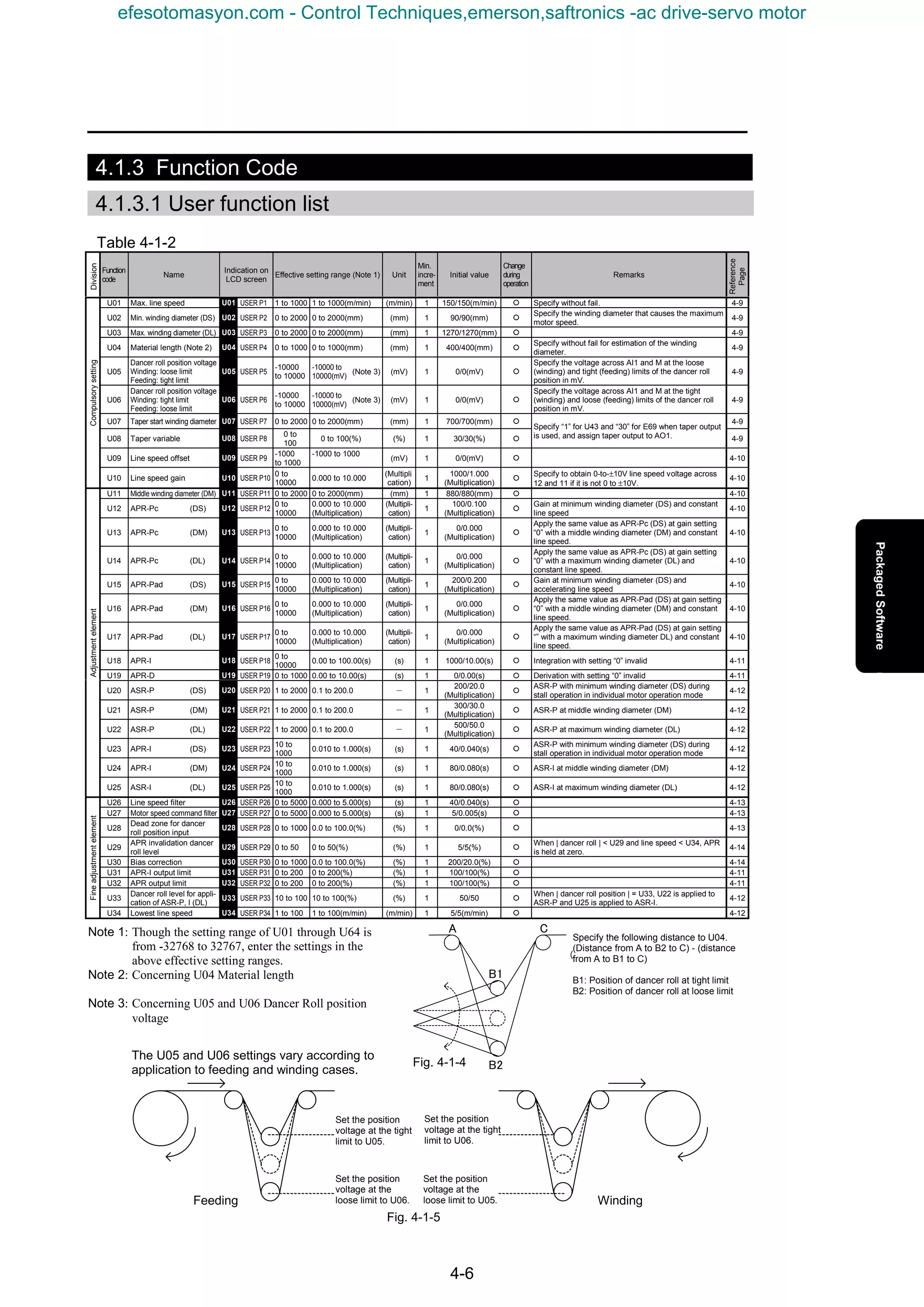
![4. Packaged Software
4-7
Table 4-1-3
Function
code
Name
Indication on
LCD screen
Effective setting range (Note 1) Unit
Min.
incre-
ment
Initial value
Change
during
operation
Remarks
U35
Initial
diameter
(DINI) (1) If U35 is not zero, this
setting becomes the winding
diameter at startup. If U35 is
zero, the above change in
the winding diameter is
canceled.
U35 USER P35 0 to 2000 0 to 2000(mm) (mm) 1 700/700(mm) ¡
(2) If U40 is “1” and [D-SET]
is assigned to X5, the setting
is written to the calculated
winding diameter when X5
[D-SET] is turned on.
4-15
U36 X1 terminal function 0: No assignment [X1-NOP]
U36 USER P36
1: Individual motor operation [M_DRV]
- 1 0 (Note 2)
Specify “25” [U-DI] at E01.
4-16
U37 X2 terminal function 0: No assignment [X2-NOP]
U37 USER P37
1: APR-I zero hold [APRIZH]
- 1 0 (Note 2)
Specify “25” [U-DI] at E02.
4-17
U38 X3 terminal function 0: No assignment [X3-NOP]
U38 USER P38
1: APR output zero hold [APRZH]
- 1 0 (Note 2)
Specify “25” [U-DI] at E03.
4-17
U39 X4 terminal function 0: No assignment [X4-NOP]
U39 USER P39
1: Winding diameter calculation hold [D_HOLD]
- 1 0 (Note 2)
Specify “25” [U-DI] at E04.
4-17
U40 X5 terminal function 0: No assignment [X5-NOP]
U40 USER P40
1: Set the initial diameter. [D_SET]
- 1 0 (Note 2)
Specify “25” [U-DI] at E05.
4-15
U41 X6 terminal function 0: No assignment [X6-NOP]
U41 USER P41
1:
Switching between winding and
feeding
[WRW]
- 1 0 (Note 2)
Specify “25” [U-DI] at E06.
4-17
U42 Ai 2 terminal function 0: No assignment [AI2-NOP]
1:
Taper variable gain: 10
VDC/100%
[TP_AIG]
2:
Initial diameter ratio: 10 VDC /
winding diameter ratio 20 times
[INI_AID]
U42 USER P42
3: Line speed gain: 10 VDC / 4 folds [LINE_AIG]
- 1
1
(Taper variable
gain)
(Note 2)
Specify “14” [U-AI] at E50
when setting “1” to “3” at
U42.
4-9
U43 AO1 terminal function 0: No assignment [AO1-NOP]
U43 USER P43
1: Taper output: 100% / 10 VDC [TP_AO1]
- 1
1
(Taper output)
(Note 2)
Specify “30” [U-AO] at E69.
4-9
U44 AO2 terminal function 0: No assignment [AO2-NOP]
U44 USER P44
1:
Dancer roll position:
±100%/DC±10V
[DAN_AO2]
- 1 0 (Note 2)
Specify “30” [U-AO] at E70.
4-18
U45 AO3 terminal function 0: No assignment [AO3-NOP]
I/Oandrelateditems
U45 USER P45
1:
Winding diameter ratio output:
Winding diameter ratio 20 times /
10 VDC
[DIA_AO3]
- 1 0 (Note 2)
Specify “30” [U-AO] at E71.
4-18
U46 Correction method (PID) 0: P+I+D
U46 USER P46
1: P+P・I+P・D
- 1
1
(P+P・I+P・D)
¡ 4-11
U47 Correction method (offset 0: Offset for motor speed command
selection)
U47 USER P47
1: Offset for line speed
- 1
1
(Line speed)
¡ 4-14
U48 Individual motor operation 0: Dancer roll control
switch
U48 USER P48
1: Individual motor operation
- 1 0 ¡
Specify “1” at U48, “0” at
F01, and “0” at F02 during
adjustment of the maximum
speed of the winding motor.
4-16
U49 Reverse rotation prevention 0:
Reverse rotation concerning the direction of
the line is made effective.
function
U49 USER P49
1:
Reverse rotation concerning the direction of
the line is prohibited.
- 1 0 ¡ 4-19
U50 Operation direction switch 0:
Forward motor rotation upon FWD command,
reverse motor rotation upon REV command
U50 USER P50
1:
Reverse motor rotation upon FWD command,
forward motor rotation upon REV command
- 1 0 (Note 2) 4-19
U51 Speed limit U51 USER P51 0 to 110 0 to 110(%) (%) 1 100/100(%) ¡ 4-19
U52
Minimum winding diameter
ratio
U52 USER P52 10 to 100
10 to 100(%): “100 (%)” indicates
the exact winding diameter.
(%) 1 100/100(%) ¡ 4-19
Controlmethod,etc.
U53 Initial value write judgment U53 USER P53 0,100:
“100” upon completion of writing
of initial value
- 1 - Do not change. -
U54 Dancer roll 0: Do not assign [DANDCT] to Y1 through Y5.
position detection signal
assignment
[DANDCT]
1: Assign [DANDCT] to Y1. Specify “25” [U-DO] at E15
2: Assign [DANDCT] to Y2. Specify “25” [U-DO] at E16
3: Assign [DANDCT] to Y3. Specify “25” [U-DO] at E17.
U54 USER P54
4: Assign [DANDCT] to Y4.
- 1 0 (Note 2)
Specify “25” [U-DO] at E18.
5: Assign [DANDCT] to Y5. Specify “25” [U-DO] at E19.
4-20
Dancerpositionsearch
U55
Dancer roll position detection
level
U55 USER P55 0 to 100 0 to 100(%) (%) 1 100/100(%) ¡
When the dancer roll
position is within this setting,
[DANDCT] turns on.
4-20
U56 U56 USER P56 -
U57 U57 USER P57 -
U58 U58 USER P58 -
U59 U59 USER P59 -
U60 U60 USER P60 -
U61 U61 USER P61 -
U62 U62 USER P62 -
U63 U63 USER P63 -
U64 Version information U64 USER P64 1 1 1100□ -
Note 1: Though the setting range of U01 through U64 is from -32768 to 32767, enter the setting in the above effective setting ranges.
Note 2: Change the setting during stoppage.
Division
Reference
Page
efesotomasyon.com - Control Techniques,emerson,saftronics -ac drive-servo motor](https://image.slidesharecdn.com/vg7upacmanual-140613044924-phpapp01/75/Vg7-upac-manual-151-2048.jpg)
![4-8
4.1.3.2 Other function codes
Table 4-1-4
Function
code
Name
Indication on
LCD screen
Effective setting range Unit
Min.
incre-
ment
Initial
value
Change
during
opera-
tion
Remarks
F01 Speed setting N1
0: Speed setting entered at the keypad panel
is valid.
F01
Speed
setting N1
0 to 7
2: Setting input at terminal 12 [0 to +10V] is
valid.
- 1 0 × -
0: Operation command entered at the keypad
panel is effective.
F02 Operation F02 Operation 0 to 1
1: Operation command input at the FWD and
REV terminals is valid.
- 1 0 ×
During regular operation:
Specify “0” at U48, “2” at F01, and “1” at
F02.
During maximum speed of winding motor:
Specify “1” at U48, “0” at F01, and “0” at
F02. -
F03
M1 maximum
speed
F03
M1 max.
speed
50 to 24000 r/m 1 1500 ×
Specify the motor speed that can achieve
the “maximum line speed” (U01) with the
“minimum winding diameter” (U02).
-
F61 ASR I-P (gain) F61 USER P6 0.1 to 200.0 UPAC overwrites data.
(Multipli-
cation)
0.1 10.0 〇
F62
ASR 1-I
(integration
constant)
F62 ASR1-I
0.010 to
1.000
UPAC overwrites data. (s) 0.001 0.200 〇
Write a value suitable for the winding
diameter from UPAC.
-
E01
X1 terminal
function
E01 X1 function 0 to 63 - 1 0 × When U36 is “1,” specify “25” [U-DI]. 4-16
E02
X2 terminal
function
E02 X2 function 0 to 63 - 1 1 × When U37 is “1,” specify “25” [U-DI]. 4-17
E03
X3 terminal
function
E03 X3 function 0 to 63 - 1 2 × When U38 is “1,” specify “25” [U-DI]. 4-17
E04
X4 terminal
function
E04 X4 function 0 to 63 - 1 3 × When U39 is “1,” specify “25” [U-DI]. 4-17
E05
X5 terminal
function
E05 X5 function 0 to 63 - 1 4 × When U40 is “1,” specify “25” [U-DI]. 4-15
E06
X6 terminal
function
E06 X6 function 0 to 63 - 1 5 × When U41 is “1,” specify “25” [U-DI]. 4-17
E09
X9 terminal
function
E09 X9 function 0 to 63 Specify “9” [THR] (external alarm). - 1 9 × Assign to the external alarm input. -
E14
X terminal function
normally open /
closed
E14
X normal
setting
0000 to 01FF Specify the part of 9 (X9) on CL side. - 1 0000 ×
The X9 (external alarm) terminal becomes a
normally closed terminal.
-
E15 Y1 terminal function E15 Y1 function 0 to 47 - 1 1 × When U54 is “1,” specify “25” [U-DO]. 4-20
E16 Y2 terminal function E16 Y2 function 0 to 47 - 1 2 × When U54 is “2,” specify “25” [U-DO]. 4-20
E17 Y3 terminal function E17 Y3 function 0 to 47 - 1 3 × When U54 is “3,” specify “25” [U-DO]. 4-20
E18 Y4 terminal function E18 Y4 function 0 to 47 - 1 4 × When U54 is “4,” specify “25” [U-DO]. 4-20
E19 Y5 terminal function E19 Y5 function 0 to 47 - 1 14 × When U54 is “5,” specify “25” [U-DO]. 4-20
E49 Ai 1 terminal function E49 Ai 1 function 0 to 18 Specify “14” [U-AI]. - 1 0 × Assign for dancer roll position input. -
E50 Ai 2 terminal function E50 Ai 2 function 0 to 18 - 1 0 × When U42 is not “0,” specify “14” [U-AI]. 4-9
E69 AO1 function E69
AO1
function
0 to 31 - 1 1 〇 When U43 is not “1,” specify “30” [U-AO]. 4-9
E70 AO2 function E70
AO2
function
0 to 31 - 1 6 〇 When U44 is not “1,” specify “30” [U-AO]. 4-18
E71 AO3 function E71
AO3
function
0 to 31 - 1 3 〇 When U45 is not “1,” specify “30” [U-AO]. 4-18
H02 All save function H02 All save 0,1
Download the UPAC software, specify “1”
at o38, and save the initial data.
- 1 0 ×
After specifying “1” at o38, STOP + □ to
specify “1” to save all initial U code data.
-
o38 UPAC start/stop o38
UPAC
operation
0 to 2 Specify “1” at o38. - 1 0 × Specify “1” at o38. -
o40 UPAC address o40
UPAC
address
100 to 255 - 1 100 ×
Specify the same “communication setting:
RS485 station number” in the UPAC system
definition as o40.
-
Reference
Page
efesotomasyon.com - Control Techniques,emerson,saftronics -ac drive-servo motor](https://image.slidesharecdn.com/vg7upacmanual-140613044924-phpapp01/75/Vg7-upac-manual-152-2048.jpg)
![4. Packaged Software
4-9
4.1.3.3 Description of each function code
KUsed for indication of the [line speed] in option monitor 4 and for calculation of estimated winding
diameter ratio at startup.
KUsed for calculation of the [calculated winding diameter] in option monitor 3. Specify the minimum
winding diameter that can be installed to the winding shaft.
KThe relationship among [M1 max. speed] (F03), [max. line speed] (U01), and [min. winding diameter]
(U02) is as shown below.
F03 [M1. max. speed] = U01 [max. line speed] / π / speed reduction ratio (< 1) / U02 [min.
winding diameter]
KSetting point for the upper limit of the calculated winding diameter and the taper variable of taper output.
KUsed for calculation of the estimated winding ratio.
The winding diameter ratio is estimated from this setting, variation in the dancer roll position input to
the Ai1 terminal, and the number of pulses of the motor PG.
KIf this setting is “0,” calculation of the estimated winding diameter ratio during startup is not made.
KSpecify the input voltage at Ai1 when the dancer roll is at the loose or tight limit.
When the input voltage at Ai1 is at this setting, the dancer roll position is supposed to be the ±100%
position.
KWhen the middle voltage between the loose and tight limits is input, the center position of the dancer
roll is supposed.
KThe setting parameter varies according to the attaching position of the dancer roll between the winding
machine and feeding machine.
Machine Voltage at loose limit Voltage at tight limit
Winding machine U05 U06
Feeding machine U06 U05
With this function, a taper characteristic voltage suitable for the winding diameter is output.
KTo use this function, U43 must be “1” and E69 must be “30,” and taper output [TP_AO1] must be
assigned to AO1.
U01 Max. line speed Setting: 0 to 1,000 / 0 to 1,000(m/min)
U02 Min. winding diameter (DS) Setting: 0 to 2,000 / 0 to 2,000(mm)
U03 Max. winding diameter (DL) Setting: 0 to 2,000 / 0 to 2,000(mm)
U04 Material length Setting: 0 to 1,000 / 0 to 1,000(mm)
U05
Dancer roll position voltage Setting: -10,000 to 10,000 /
Winding: loose limit / feeding: tight limit -10,000 to 10,000(mV)
U06
Dancer roll position voltage Setting: -10,000 to 10,000 /
Winding: tight limit / feeding: loose limit -10,000 to 10,000(mV)
U07 Taper start winding diameter Setting: 0 to 2,000 / 0 to 2,000(mm)
U08 Taper variable Setting: 0 to 100 / 0 to 100 (%)
U42 Ai 2 terminal function Setting: 0 to 3
U43 AO1 terminal function Setting: 0, 1
E50 Ai2 terminal function Setting: 0 to 18
E69 AO1 terminal function Setting: 0 to 31
efesotomasyon.com - Control Techniques,emerson,saftronics -ac drive-servo motor](https://image.slidesharecdn.com/vg7upacmanual-140613044924-phpapp01/75/Vg7-upac-manual-153-2048.jpg)
![4-10
Fig. 4-1-6
(1) When U43 is “1” and E50 is “14,” the input at Ai2 becomes the gain concerning the [taper variable] (U08).
Taper variable = U08 [taper variable] x input at Ai1 (V) / 10 (V)
(2) Other than above (1)
Taper variable = U08 [taper variable]
* The output voltage at AO1 is smaller as the taper variable is larger.
KUse this function to correct the line speed (input across 12 and 11) to the 10 (V) line speed
specification.
Example: When 0.5 (V) is obtained at the “0” line speed and 7.5 (V) is obtained at the maximum line speed
U09 [line speed offset] = -500: Correction of 0.5 (V)
U10 [line speed gain] = 10 / (7.5 - 0.5) x 1,000 = 1,429 (1,429 times)
KConcerning APR-P
With the APR (Auto Position Regulator)-P term, the deviation of the dancer roll position input
multiplied by the setting is output.
KThe gain (Pc) at the constant line speed and the gain (Pad) during acceleration and deceleration can be
individually specified.
KValues at the three points (minimum winding diameter (DS), middle winding diameter (DM), and
maximum winding diameter (DL) can be specified.
When the settings (U13, U14, U16 and U17) at the middle winding diameter (DM) and the maximum
winding diameter (DL) are specified at “0,” the settings (U12 and U15) for the minimum winding
diameter (DS) is applied to the maximum winding diameter. (Flat characteristic)
10V
U07
Taper start
winding diameter
U03
Max. winding
diameter
U02
Min. winding
diameter
*
Winding diameter
AO1 output
U09 Line speed offset Setting: -1,000 to 1,000 / -1,000 to 1,000 (mV)
U10 Line speed gain Setting: 0 to 10,000 / 0 to 10.000 (Multiplication)
U11 Middle winding diameter (DM) Setting: 0 to 2,000 / 0 to 2,000(m/min)
U12 APR-Pc(DS) Setting: 0 to 10,000 / 0.000 to 10.000 (Multiplication)
U13 APR-Pc(DM) Setting: 0 to 10,000 / 0.000 to 10.000 (Multiplication)
U14 APR-Pc(DL) Setting: 0 to 10,000 / 0.000 to 10.000 (Multiplication)
U15 APR-Pc(DS) Setting: 0 to 10,000 / 0.000 to 10.000 (Multiplication)
U16 APR-Pc(DM) Setting: 0 to 10,000 / 0.000 to 10.000 (Multiplication)
U17 APR-Pc(DL) Setting: 0 to 10,000 / 0.000 to 10.000 (Multiplication)
efesotomasyon.com - Control Techniques,emerson,saftronics -ac drive-servo motor](https://image.slidesharecdn.com/vg7upacmanual-140613044924-phpapp01/75/Vg7-upac-manual-154-2048.jpg)
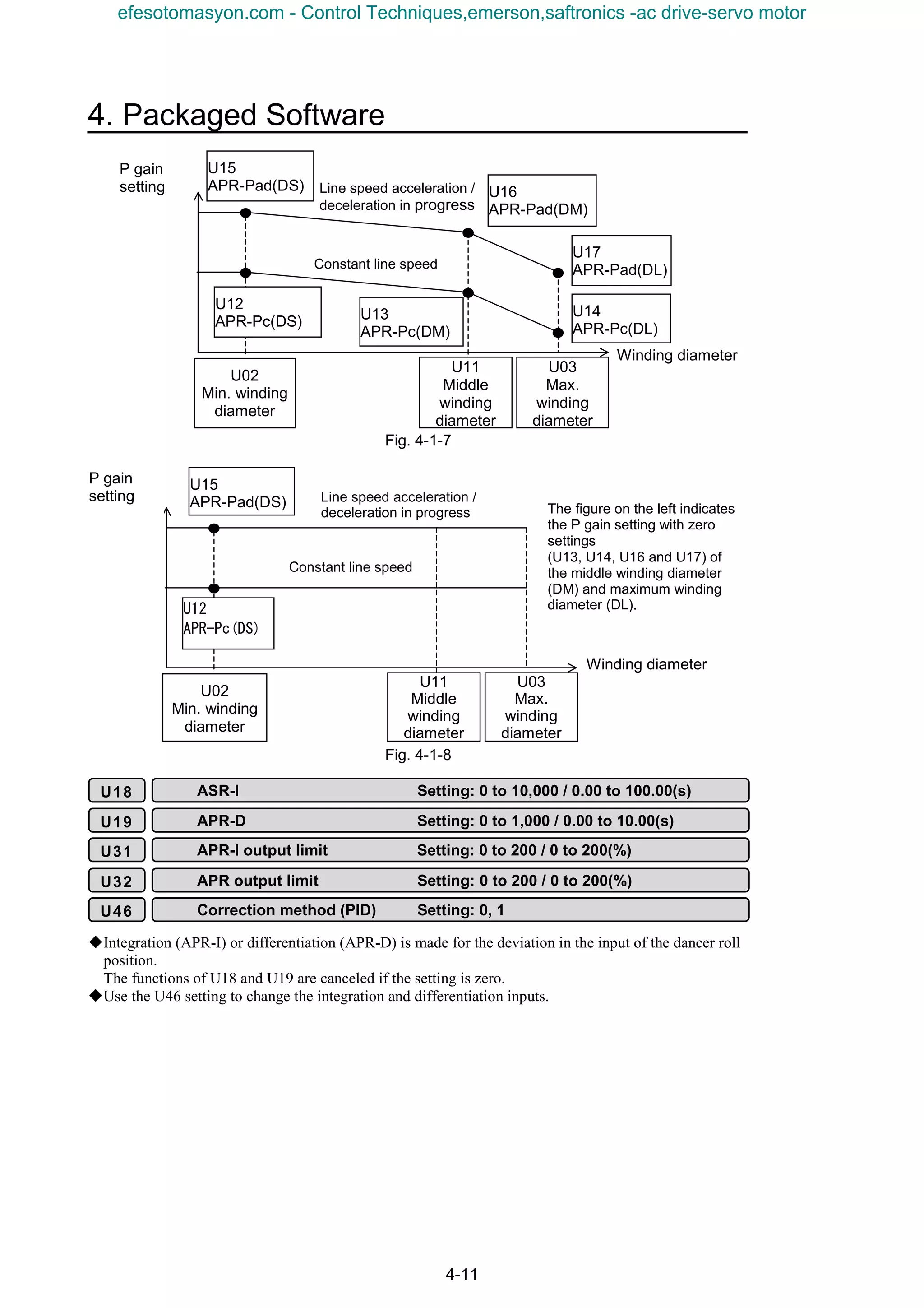
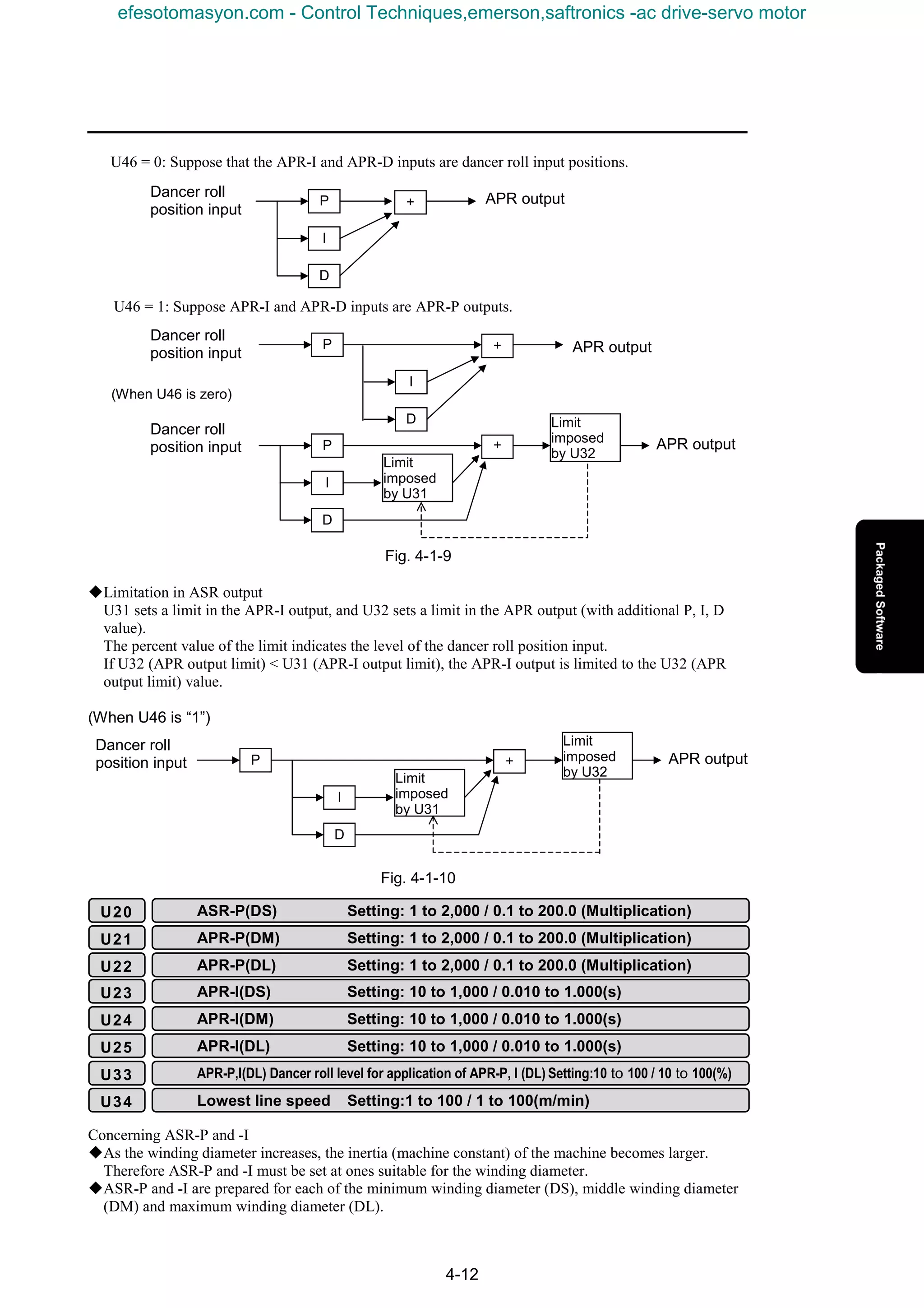
![4. Packaged Software
4-13
Fig. 4-1-11
Fig. 4-1-12
KConcerning ASR-P and -I during line stoppage
ASR-P and -I at a line speed smaller than the [lowest line speed] (U34) are adjusted to U20 (ASR-P) and
U23 (ASR-I) equivalent to the minimum winding diameter (DS) without relations to the current winding
diameter. (This is to prevent the winding shaft from moving slightly during stoppage of the line.)
KAdjustment of ASR-P and -I according to position of dancer roll [Application when the current
winding diameter ≥ middle winding diameter (DM)]
The dancer roll must be returned to the center quickly if it is far from the center. If the winding diameter
is large, the mechanical inertia is large, too, so that ASR-P must be increased.
If the current winding diameter is equal to or larger than the middle winding diameter (DM) and the
danger roll position is equal to or larger than U33 [dancer roll level for application of ASR-P and -I (DL)],
ASR-P and -I are made U22 (ASR-P) and U25 (ASR-I) for the maximum winding diameter (DL).
If the above-mentioned “line stoppage” and “danger roll position” conditions overlap (for example, if the
dancer roll position is larger than U33 after controlled stop at a large winding diameter), the “dancer roll”
condition is given priority and ASR-P and -I for the maximum winding diameter (DL) are applied.
KThe [line speed filter] (U26) is a filter applied to the line speed that is input across 12 and 11.
Use this filter if there is fluctuation in the line speed signal issued by the sender.
KThe [motor speed command filter] (U27) is a filter applied to the motor speed command calculated
with UPAC.
Use it when hunting is observed in the motor.
KUse the setting if there is variation in the dancer roll position input (across Ai1 and M) around the
center to prevent the dancer roll from becoming stable.
U11
Middle winding
diameter
U03
Max. winding
diameter
U02
Min. winding
diameter
U20
ASR-P(DS)
U21
ASR-P(DM)
U22
ASR-P(DL)
APR-P
Winding diameter
U11
Middle winding
diameter
U03
Max. winding
diameter
U02
Min. winding
diameter
U23
ASR-P(DS)
U24
ASR-P(DM)
U25
ASR-P(DL)
APR-I
Winding diameter
U26 Line speed filter Setting: 0 to 5,000 / 0.000 to 5.000(s)
U27 Motor speed command filter Setting: 0 to 5,000 / 0.000 to 5.000(s)
U28 Dead zone for dancer roll position input Setting: 0 to 1,000 / 0.0 to 100.0(%)
efesotomasyon.com - Control Techniques,emerson,saftronics -ac drive-servo motor](https://image.slidesharecdn.com/vg7upacmanual-140613044924-phpapp01/75/Vg7-upac-manual-157-2048.jpg)
![4-14
Fig. 4-1-13
KIf there is slight fluctuation in the dancer roll position during stoppage of the line, integration or other
correction measures may function, causing slight motion of the motor.
To avoid such phenomenon, the APR output is held at zero if the dancer roll position is smaller than
[APR invalidation dancer roll level] (U29) to prevent the motor from slight motions.
KThe line stoppage judgment is made in comparison between the line speed input (across 12 and 11) and
[lowest line speed] (U34). Line stoppage is judged if the line speed is smaller than U34.
The APR output is multiplied by the line speed to produce the offset. A sufficient offset cannot be
obtained if the line speed is zero (line stoppage) or it is low. Therefore a “high selector” (priority is given
on the higher one) setting is prepared for the line speed multiplied by the APR, so that a sufficient offset
can be obtained even if the line speed is low.
KConcerning correction method
Selection between the offset (⊿V*) as to the line speed and motor speed command (⊿N*) can be
made for the offset of the dancer roll. The “offset” displayed at [option monitor 6] changes between the
line speed and motor speed according to the setting at the [correction method (offset selection)] (U47).
Fig. 4-1-14
0
U28
Dead zone
Dancer roll
position input
Dead zone output (APR input)
APR output
Line speed
×
U30
Bias correction
÷
Winding diameter ratio
⊿N*
Offset concerning motor
speed command
Displayed at option monitor 6
If U47 = 0 (correction concerning motor speed command)
U29 APR invalidation dancer roll level Setting: 0 to 50 / 0 to 50(%)
U34 Lowest line speed Setting: 1 to 100 / 1 to 100(m/min)
U30 Bias correction Setting: 0 to 1,000 / 0.0 to 100.0(%)
U47 Correction method (offset selection) Setting: 0, 1
efesotomasyon.com - Control Techniques,emerson,saftronics -ac drive-servo motor](https://image.slidesharecdn.com/vg7upacmanual-140613044924-phpapp01/75/Vg7-upac-manual-158-2048.jpg)
![4. Packaged Software
4-15
図 4-1-15
Fig. 4-1-15
KCalculated winding diameter at startup based on initial diameter
If [initial diameter] (U35) is not zero
When an operation command (FWD, REV) is issued, the calculated winding diameter immediately
becomes the winding diameter specified at U35.
When the operation command is stopped, a new winding diameter is judged and operation starts at the
initial diameter.
The winding diameter at startup can be adjusted to a middle diameter with these settings for stable
motor speed command at startup. (If the previous winding diameter is almost the minimum winding
diameter and the actual winding diameter is around the maximum winding diameter, the motor speed
command increases substantially, causing large shock.)
Fig. 4-1-16
If U35 [initial diameter] setting = 0
If the[initial diameter] (U35) setting is zero, the calculated winding diameter remains the previous
value and operation starts even when the operation command (FWD, REV) is issued.
Fig. 4-1-17
APR output
Line speed
×
U30
Bias correction
⊿N*
Offset concerning line speed
Displayed at option monitor 6
If U47 = 0 (correction concerning motor speed
)
U35 Initial diameter Setting: 0 to 2,000 / 0 to 2,000(mm)
U40 X5 terminal function Setting: 0, 1
E05 X5 terminal function Setting: 0 to 63
Winding diameter calculation stop
Operation
command
Calculated
winding
diameter
off onon
off onon
U35
Initial
diameter
Winding diameter calculation stop
Operation
command
Calculate
d winding
diameter
efesotomasyon.com - Control Techniques,emerson,saftronics -ac drive-servo motor](https://image.slidesharecdn.com/vg7upacmanual-140613044924-phpapp01/75/Vg7-upac-manual-159-2048.jpg)
![4-16
KInitial value setting through contact input
When the new winding diameter is already known, assign [initial diameter set] to contact input X5 to set
the winding diameter (initial diameter; U35) to the calculated winding diameter while this signal is issued.
Setting for assigning initial diameter set [D_SET] to X5
U40=1
E05=25[U-DI]
* Note: Use a temporary command for the X5 signal assigned to the initial diameter setting. If the
signal remains turned on, the calculated winding diameter is fixed at the [initial diameter] (U35).
KDancer roll control and individual motor operation switching
Individual motor operation indicates the operation method of the standard VG7 without dancer roll
control or winding diameter calculation, where only speed commands are given.
The switching method between dancer roll control operation and individual motor operation includes
two variations: contact input X1 and parameter.
KContact input switching
Assign the individual motor operation [M_DRV] to X1 in the following setting.
After assignment, the individual motor operation mode continues while X1 [M_DRV] remains turned
on.
U36=1
E01=25[U-DI]
KParameter switching
Specify “1” at [individual motor operation switch] (U48) to start the individual motor operation mode.
(Specify “0” at [individual motor operation switch] (U48) to start the dancer roll control operation
mode.)
* The individual motor operation mode starts when X1 [M_DRV] is turned on or U48 is “1.”
off onon
Winding diameter calculation stop
on
Operation
command
Calculated
winding
diameter
Initial diameter
setting
Fig. 4-1-18
U36 X1 terminal function Setting: 0, 1
U48 Individual motor operation switching Setting: 0, 1
E01 X1 terminal function Setting: 0 to 63
efesotomasyon.com - Control Techniques,emerson,saftronics -ac drive-servo motor](https://image.slidesharecdn.com/vg7upacmanual-140613044924-phpapp01/75/Vg7-upac-manual-160-2048.jpg)
![4. Packaged Software
4-17
KAPR-I output zero hold
Assign APR-I zero hold [APRIZH] to X2 in the following settings.
After assignment, the APR-I output is held at zero while X2 [APRIZH] is turned on.
U37=1
E02=25[U-DI]
KAPR output zero hold
Assign APR zero hold [APRIZH] to X3 in the following settings.
After assignment is made, the APR-I output is held at zero while X3 [APRZH] is turned on.
U38=1
E03=25[U-DI]
The APR-I integration value, too, is held at zero when X3 [APRZH] is turned on.
KWinding diameter calculation hold
Assign winding diameter calculation hold [D_HOLD] to X4 in the following settings. After
assignment, the previous value of the calculated winding diameter is held while X4 [D_HOLD] is
turned on.
U39=1
E04=25[U-DI]
KWinding / feeding switching
Use the setting in a system where a feeding roll, idler, and winding roll are included and there are two
line directions, to switch the line direction.
Fig. 4-1-19
As described at the * mark, after the line direction changes and the winding roll becomes the feeding
roll, the correction polarity of the dancer roll becomes reverse, therefore X6 [WRW] must be used to
switch the polarity of the dancer roll position input.
Specify both rolls (winding and feeding rolls on the left and right of the above figure) as a winding roll
when specifying the dancer roll position input at U05 and U06.
U41=1
E06=25[U-DI]
U37 X2 terminal function Setting: 0, 1
E02 X2 terminal function Setting: 0 to 63
U38 X3 terminal function Setting: 0, 1
E03 X3 terminal function Setting: 0 to 63
U39 X4 terminal function Setting: 0, 1
E04 X4 terminal function Setting: 0 to 63
U41 X6 terminal function Setting: 0, 1
E06 X6 terminal function Setting: 0 to 63
Feeding Idler Winding
* Winding dancer roll
Speed increase upon
sag
Winding dancer roll
Speed decrease upon
sag
Winding FeedingIdler
efesotomasyon.com - Control Techniques,emerson,saftronics -ac drive-servo motor](https://image.slidesharecdn.com/vg7upacmanual-140613044924-phpapp01/75/Vg7-upac-manual-161-2048.jpg)
![4-18
KSelect assignment of Ai2.
To specify 1 to 3 at U42 to assign Ai2 for dancer roll control, E50 [Ai2 terminal function] must be
specified at “14” [U-Ai].
U42 = 0:No assignment
U42 = 1:Taper variable gain [TP_AIG]
U42 = 2:Initial diameter ratio [INI_AID]
When the above settings are given, an input at Ai2 determines the initial diameter instead of the initial
diameter specified at U35.
Effective when X5 [D_SET] is turned on, 20 times winding diameter ratio upon +10 VDC input.
U42 = 3:Line speed gain [LINE_AIG]
Specify the gain for the line speed input across 12 and 11, using the input at Ai2. The setting is
multiplied by four upon +10 VDC.
KDancer roll position output
The current dancer roll position is output at AO2. These settings are used for indication of the dancer
roll position at an instrument.
The output is +10 VDC for dancer a roll position of ±100%.
Assign the dancer roll position [DAN_AO2] to AO2 in the following settings.
U44=1
E70=30[U-AO]
KWinding diameter ratio output
The calculated current winding diameter ratio is output at AO3. The output is +10 VDC when the
winding diameter ratio is 20 times.
Assign the winding diameter ratio output [DIA_AO3] to AO3 in the following settings.
U45=1
E71=30[U-AO]
U42 Ai2 terminal function Setting: 0, 3
E50 Ai2 terminal function Setting: 0 to 18
U44 AO2 terminal function Setting: 0, 1
E70 AO2 terminal function Setting: 0 to 31
U45 AO3 terminal function Setting: 0, 1
E71 AO3 terminal function Setting: 0 to 31
efesotomasyon.com - Control Techniques,emerson,saftronics -ac drive-servo motor](https://image.slidesharecdn.com/vg7upacmanual-140613044924-phpapp01/75/Vg7-upac-manual-162-2048.jpg)
![4. Packaged Software
4-19
KSelect the correction method for a tight dancer roll during stoppage of the line.
U49 = 0:Reverse rotation in the line direction is valid
When the dancer roll is at position A in a tight state as shown in the figure below, the winding motor is
reversed in the line direction to return the dancer roll to the center.
Fig. 4-1-20
U49 = 1:Prohibit reverse rotation in line direction.
If the dancer roll is at position A in a tight state as shown in the figure below, rotation of the winding
motor is limited.
Use this function to limit the rotation in the loosening direction, such as for metallic materials.
Fig. 4-1-21
KUse the setting to reverse the motor with an FWD command.
U50 = 0:FWD command for forward motor rotation, REV command for reverse motor rotation
U50 = 1:FWD command for reverse motor rotation, REV command for forward motor rotation
* Change the parameter during stoppage.
KSpeed limit
The limit applies to the motor speed command added with the dancer roll speed offset.
KMinimum winding diameter ratio
The minimum winding diameter, which is specified at the [minimum winding diameter] (U02) during
regular operation, can be specified in % of the U02 setting, with “1” being the minimum winding
diameter ratio.
The value specified in this parameter is the lowest limit of the minimum calculated winding diameter.
Line direction
Rotates.
A
B
Line direction
Failure to rotate
A
(B)
U49 Reverse rotation prevention function Setting: 0, 1
U50 Operation direction switching Setting: 0, 1
U51 Speed limit Setting: 0 to 110 / 0 to 110(%)
U52 Minimum winding diameter ratio Setting:10 to 100 / 10 to 100(%)
efesotomasyon.com - Control Techniques,emerson,saftronics -ac drive-servo motor](https://image.slidesharecdn.com/vg7upacmanual-140613044924-phpapp01/75/Vg7-upac-manual-163-2048.jpg)
![4-20
KThe dancer roll position is detected and output in an on/off DO output signal [DANDCT].
Fig. 4-1-22
Specify the parameter (E15 to E19) settings of the assigned DO output at “25” [U-DO] and set U54 as
shown below.
U54 = 0:No assignment to Y1 to Y5
U54 = 1:Assign to Y1
U54 = 2:Assign to Y2
U54 = 3:Assign to Y3
U54 = 4:Assign to Y4
U54 = 5:Assign to Y5
4.1.3.4 Option monitor
Table 4-1-5
Function
code
Name
Indication on
LCD screen
Data displaying range Unit
Minimum
increment
Remarks
OP1
OP2
OP3
Calculated
winding
diameter
Option monitor 3 0 to 2000 0 to 2000(mm) (mm) 1
OP4
Line speed
Option monitor 4 0 to 1000
0 to
1000(m/min)
(m/min) 1
OP5
Dancer roll
position
Option monitor 5
-200 to
200
-200 to 200(%) (%) 1
When a voltage specified at U05 or U06 is input, ±100 (%) is
displayed.
OP6 Offset Option monitor 6
-100 to
100
-100 to 100(%) (%) 1
The maximum line speed or maximum motor speed is assumed to
be 100%.
Dancer roll position
U55
Dancer roll position
detection level
on
off off
0
[DAN_DCT]
Hysteresis 1%
U54 Dancer roll position detection signal assignment Setting: 0 to 5
U55 Dancer roll position detection level Setting: 0 to 100 / 0 to 100(%)
E15 Y1 terminal function Setting: 0 to 47
E16 Y2 terminal function Setting: 0 to 47
E17 Y3 terminal function Setting: 0 to 47
E18 Y4 terminal function Setting: 0 to 47
E19 Y5 terminal function Setting: 0 to 47
efesotomasyon.com - Control Techniques,emerson,saftronics -ac drive-servo motor](https://image.slidesharecdn.com/vg7upacmanual-140613044924-phpapp01/75/Vg7-upac-manual-164-2048.jpg)
![4. Packaged Software
4-21
4.2 WPS-VG7-POS
WPS-VG7-POS is packaged software for controlling the orientation position.
(Windows Personal Computer Software Package-Position control system on VG7S)
The package features the following items.
• The encoder resolution can be selected from seven options of 128, 256, 512, 1024, 2048, 4096, and
8192 according to the requirement of the stopping accuracy of the machine shaft.
• Four stopping position commands can be preset inside, among which the target one is selected with a
contact.
• The stopping position command can be given externally from our MICREX series PLC, 16-point
digital input, RS485 communication via POD or the like, or Field Bus. The stopping position latch
function can be used to stop at multiple points.
• Because the orientation function is shared by the UPAC option, all the standard functions of the VG7
inverter can be used without limitations.
To realize the orientation function, the MCA/OPC-VG7-PG option is necessary in addition to the UPAC
option. For the hardware specification, installation method and other details of the option, refer to the
VG7S USER’S MANUAL (MEH407).
This packaged software is included in the CD-ROM of WPS-VG7-PCL (loader software) and provided
free of charge. To configure a system using this package, agreement with the following description is
necessary.
[Terms of Agreement]
You are requested to agree with the following items.
If you do not agree with them, do not use WPS-VG7-POS packaged software.
For inquiries about the agreement items, contact our sales person.
(1) Function codes UNO.01 through 63 used for orientation control are set at “0” before shipment from
our factory. The user must change the setting of necessary parameters voluntarily according to the
purpose.
(2) A built-in battery of UPAC backs the data. The life of the battery is five years (at 25 °C). The
battery life is reduced during operation at higher temperatures. When the battery life is reached,
UPAC alarm “ErA” is displayed. If this alarm is displayed, change the battery soon. For the battery
replacement method, refer to the corresponding part of this manual.
(3) If noise or vibration occurs due to resonance in the mechanical system or play in the gear, the
mechanical system must be examined and adjusted. If the noise is not reduced after adjustment of
the mechanical system, electrical countermeasures must be taken, so that the standard functions of
VG7, gain and integration time of orientation control, filter and other parameters are used for
adjustment. Please note that we will not meet requests to add special control applications to UPAC
or to the main body of VG7.
(4) Reproduction of the whole or a part of the program or leasing or selling to the third party is
prohibited in the scope of the Japanese Copyright Law.
(5) There are no limitations to voluntary addition, change, or deletion by the customer for program
development based on this dancer control program. We will provide cooperation and consultation
for technical support concerning program development.
(6) We will assume no responsibility for the direct or indirect material losses or damage caused by the
WPS-VG7-POS program itself or change, addition or deletion to the program.
I agree with the above description. _______________ (Signature)
efesotomasyon.com - Control Techniques,emerson,saftronics -ac drive-servo motor](https://image.slidesharecdn.com/vg7upacmanual-140613044924-phpapp01/75/Vg7-upac-manual-165-2048.jpg)
![4-22
4.2.1 Examination of System
4.2.1.1 Specification
Table 4-2-1
Item Orientation specification
Model of option card
OPC-VG7-UPAC
OPC-VG7-PG (PD)
Packaged software
Orientation package. Version No. 13 (Displayed at function code UNO.01
and 64)
Stopping position
Stopping position setting = external stopping position setting + internal stopping
position setting
For example, with 30° internal and 10° external commands, 40°.
External stopping position
setting
Any of the following interface can be used to set.
(1) OPC-VG7-TL (T-Link card) + Fuji’s MICREX
(2) OPC-VG7-DIO (DIOB) card
(3) Standard RS485
* (1) and (3): Function code S05 “Orientation position command” is used to write.
Internal stopping position
setting
(When the external stopping
position setting is used, this
setting may be a value for
offset adjustment.)
Four points can be specified using the UNO function code. General-purpose input
terminals are combined to switch among them.
When using this function, assign the [U-DI] function to [X6] and [X7].
[X6], [X7] = OFF, OFF → UNO. 20. Stopping position setting 1 is validated.
[X6], [X7] = ON, OFF → UNO. 21. Stopping position setting 2 is validated.
[X6], [X7] = OFF, ON → UNO. 22. Stopping position setting 3 is validated.
[X6], [X7] = ON, ON → UNO. 23. Stopping position setting 4 is validated.
Control command
Use any of the following setting. Use function code UNO. 04 to select among them.
However, there are limitations when using a 4096 or 8192 p/r pulse encoder. (See section 5-2-4.)
(1) OPC-VG7-TL (T link card) + Fuii’s MICREX (function code: UNO. 04 = 2)
(2) OPC-VG7-DIO (DIOB) card (function code: UNO. 04 = 1)
(3) Standard RS485 (function code: UNO. 04 =2)
(4) Standard terminal function ([X1], [X2] and [X3]) (function code: UNO. 04 = 0). [U-DI]
must be assigned.
* (1) and (3): Function code S05 “Orientation position command” is used to write.
Orientation command
Issue this signal during FWD or REV operation to lock at the target stopping position.
Cancel the signal for operation under regular speed control.
Low speed direction command Define the direction of rotation for orientation from a stopping state.
Position change command
Function for latching the external stopping position command. The command is
latched upon the rising edge.
Repeatability
Varies according to the encoder resolution installed to the machine shaft.
Be sure to specify function code UNO. 09 according to the resolution of the installed encoder.
±±±±0.703°°°° (function code: UNO. 09 = -3, for 128 P/R pulse encoder on machine shaft)
±±±±0.352°°°° (function code: UNO. 09 = -2, for 128 P/R pulse encoder on machine shaft)
±±±±0.176°°°° (function code: UNO. 09 = -1, for 128 P/R pulse encoder on machine shaft)
±±±±0.088°°°° (function code: UNO. 09 = 0, for 128 P/R pulse encoder on machine shaft)
±±±±0.044°°°° (function code: UNO. 09 = 1, for 128 P/R pulse encoder on machine shaft)
±±±±0.022°°°° (function code: UNO. 09 = 2, for 128 P/R pulse encoder on machine shaft)
±±±±0.011°°°° (function code: UNO. 09 = 3, for 128 P/R pulse encoder on machine shaft)
* Note: The positioning accuracy is for rotation in a uniform direction. The
stopping accuracy deteriorates in a system with forward and reverse rotation.
Pulse encoder specification
Pulse encoder specification: RS422A, line driver specification (SN75113, 26LS31)
A, A signal : B, B signal : Z, Z signal : 1 P/R
The underlined part indicates the reverse signal.
The Z-phase is necessary for judgment of the reference stopping position. Be sure to select the Z-phase.
Resistive torque
Possible up to the maximum value of the motor (PI control)
* The displacement increases temporarily in response to instantaneous load torques.
* Adjust the resistance torque using the speed control gain, integration time and
orientation gain.
Mechanical conditions
Max. allowable input to PG card: 500 kHz
Speed steps: 4; [RT1] and [RT2] are used.
[RT1], [RT2] = OFF, OFF → Gain setting 1 is validated.
[RT1], [RT2] = ON, OFF → Gain setting 2 is validated.
[RT1], [RT2] = OFF, ON → Gain setting 3 is validated.
[RT1], [RT2] = ON, ON → Gain setting 4 is validated.
Orientation specification
Random access stopping direction selection, speed boosting to stop in the shortest
path, stopping without speed boosting and other functions can be selected.
Control state output function
Orientation signal and orientation completion signal are output.
To use this function, assign the [U-DO] function to [Y1] and [Y2].
[Y1] Orientation completion signal output
[Y2] Orientation signal output
Off-delay and on-delay operations of the above output signals are possible. The
orientation completion width can be set.
Monitor function
The following data items can be referred to at real time on the LED monitor at the
keypad panel.
Option monitor 3; Stopping position command
Option monitor 4; Z-phase reference shaft position
Option monitor 5; Position deviation (stopping position command - current position)
efesotomasyon.com - Control Techniques,emerson,saftronics -ac drive-servo motor](https://image.slidesharecdn.com/vg7upacmanual-140613044924-phpapp01/75/Vg7-upac-manual-166-2048.jpg)
![4. Packaged Software
4-23
4.2.1.2 Definition of operation
Fig. 4-2-1
Table 4-2-2
Item Description
N1: Slow speed 1 Motor speed set at slow speed 1 (UNO. 10 to 13)
N2: Slow speed 2 Speed of two times the ORT gain (UNO 14 to 17)
Correction mode
After the ORT command is input, the speed command is corrected from N1
according to the position feedback signal issued from the shaft encoder.
Control zone Range of ±11.25° to target stopping point
There are two patterns in the operation: stopping at the target position during operation at a speed, and
rotation to the target position in a stopping state at zero speed. Be sure to combine with the FWD or REV
operation command. The direction of rotation of ORT from operation depends on the FWD or REV
command. ORT from the stopping state is in the random access direction toward the target position or
slow speed direction command.
1) ORT from running state
2) ORT from stopping state
Target stopping
point
Correction mode
Control zone
ORT command
N1
N2
Shaftspeed
-360.00° -11.25° 0
Machine shaft
11.25°
Stop
at target
position
[FWD]
]
[REV]
[ORT]
Motor
speed
0
Stop at target position
Unlock
Servo lock
Fig. 4-2-2
[FWD]
[REV]
[ORT]
Motor
speed
0
Stop at target position Stop at target position
Unlock
Servo lockServo lock
Zero
speed
Fig. 4-2-3
efesotomasyon.com - Control Techniques,emerson,saftronics -ac drive-servo motor](https://image.slidesharecdn.com/vg7upacmanual-140613044924-phpapp01/75/Vg7-upac-manual-167-2048.jpg)
![4-24
4.2.1.3 Master device
The interface on the VG7S side must be selected according to the master device for issuing stopping
position and controlling commands (such as orientation command). Refer to the following flow chart for
examination.
* Similar setting can be made with the Field Bus option.
* You can use PLC, PC, POD (Programmable Operation Display) or other host devices with RS485.
Source of
stopping position
command
External device
Inside
Use Fuji’s PLC?
Install the OPC-VG7-DIO
(B) card
Internal setting?
Specify the stopping position
at UNO. 20 to 23 and switch
using [X6] and [X7].
Use the sequence function of
UPAC. Arrange the
development environment.
Install the OPC-VG7-TL
card.
Selection of stopping
position command
Yes
No Yes
No
Use I/O operation
of PLC to set?
Use the built-in RS485. RS485
communication capability is
necessary for the PLC.
Yes
Use RS485.
Source of control
command
External device
Inside
Use Fuji’s PLC?
Install the OPC-VG7-DIO (B)
card.
Use standard
control terminal?
Use contacts [X1], [X2]
and [X3].
Use the sequence function of
UPAC. Arrange the
development environment.
Install the OPC-VG7-TL
card.
Selection of control
command
Yes
No Yes
No
Use I/O operation
of PLC to drive?
Use the built-in RS485. RS485
communication capability is
necessary for the PLC.
Yes
Use RS485.
efesotomasyon.com - Control Techniques,emerson,saftronics -ac drive-servo motor](https://image.slidesharecdn.com/vg7upacmanual-140613044924-phpapp01/75/Vg7-upac-manual-168-2048.jpg)
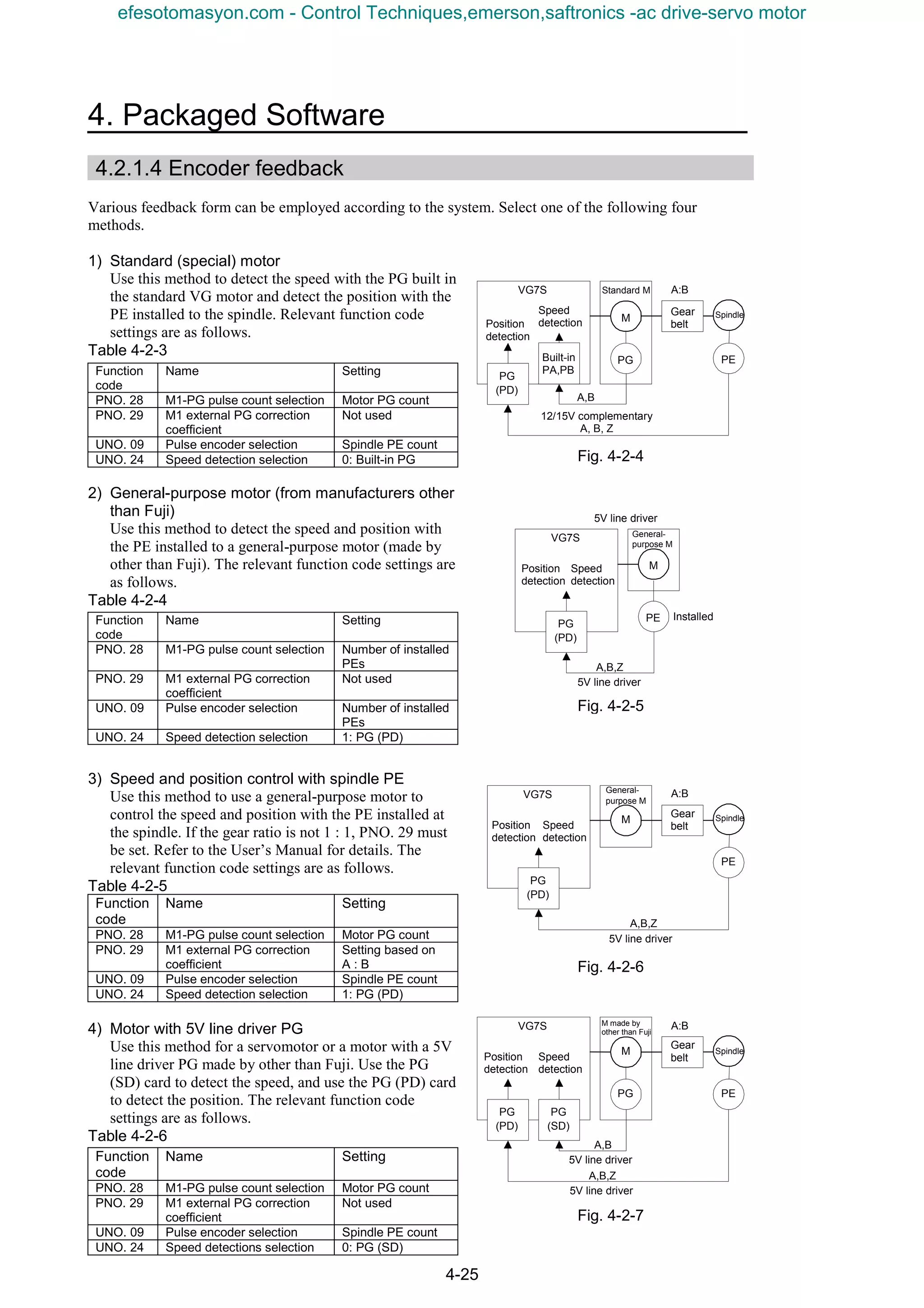
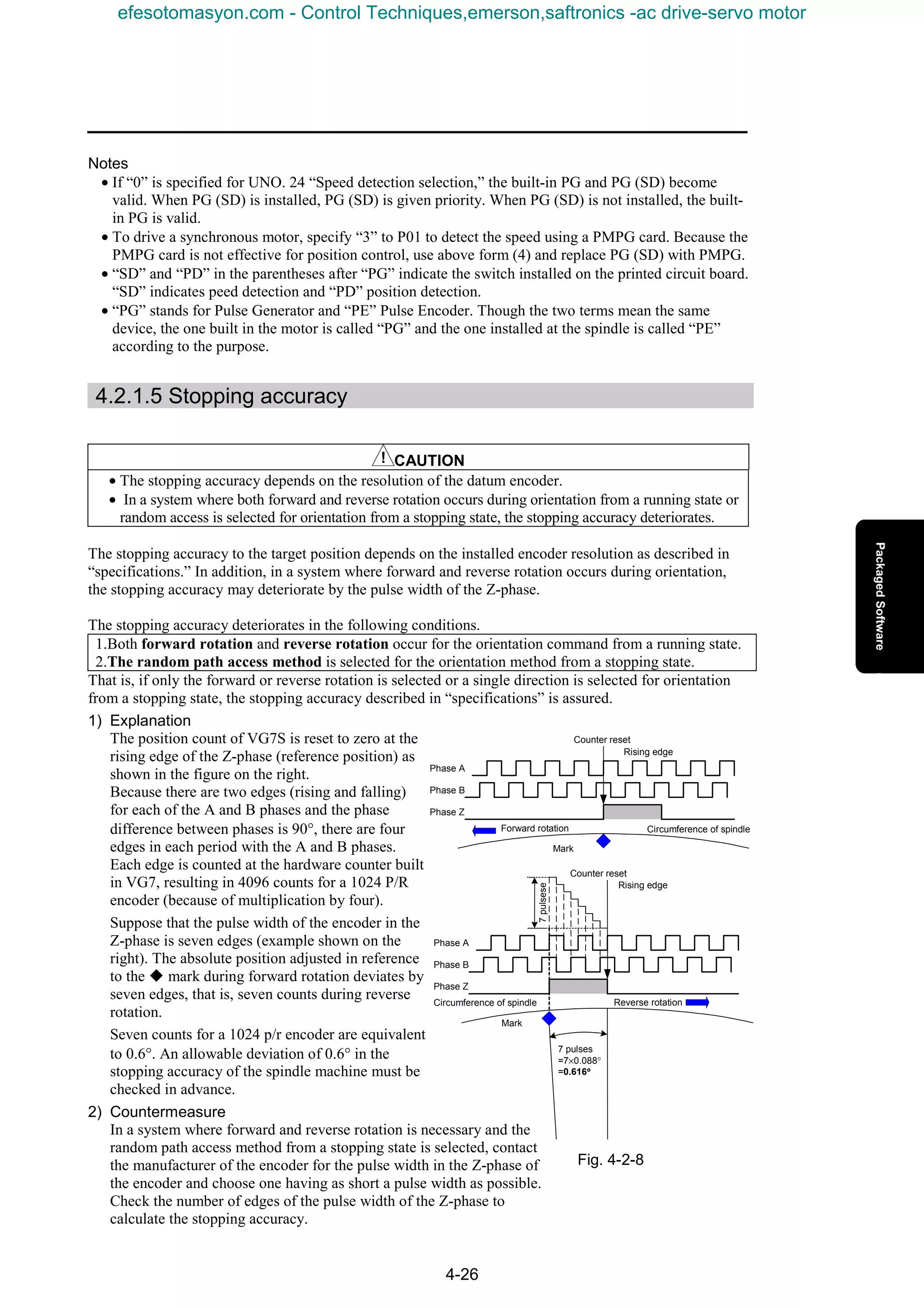
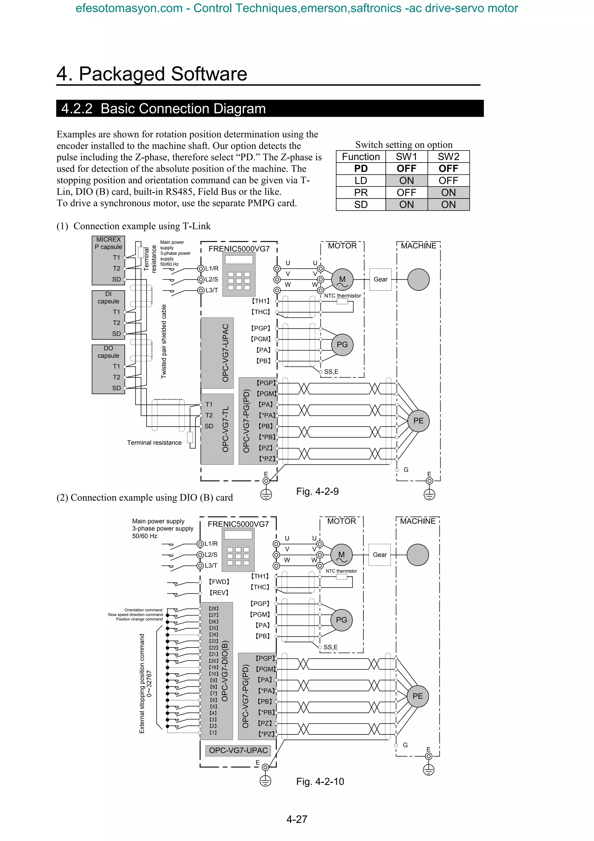
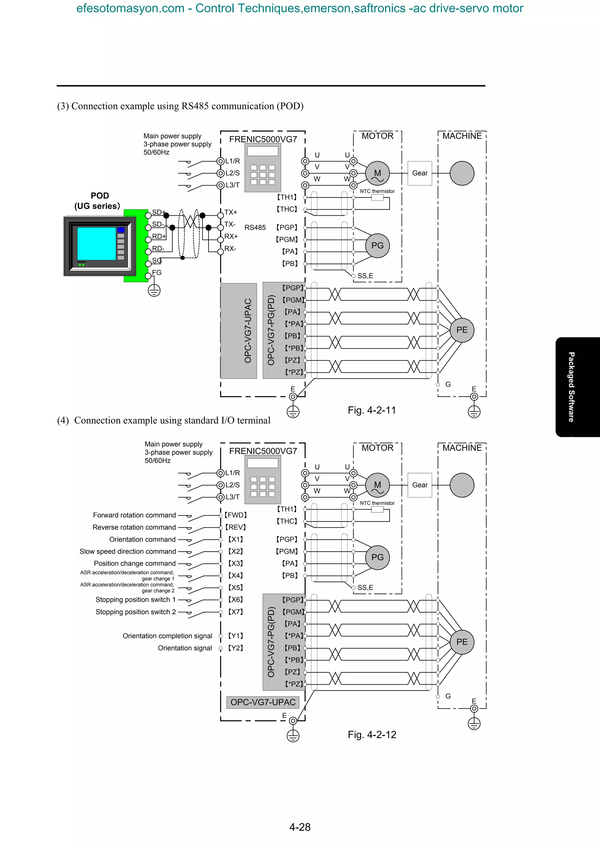
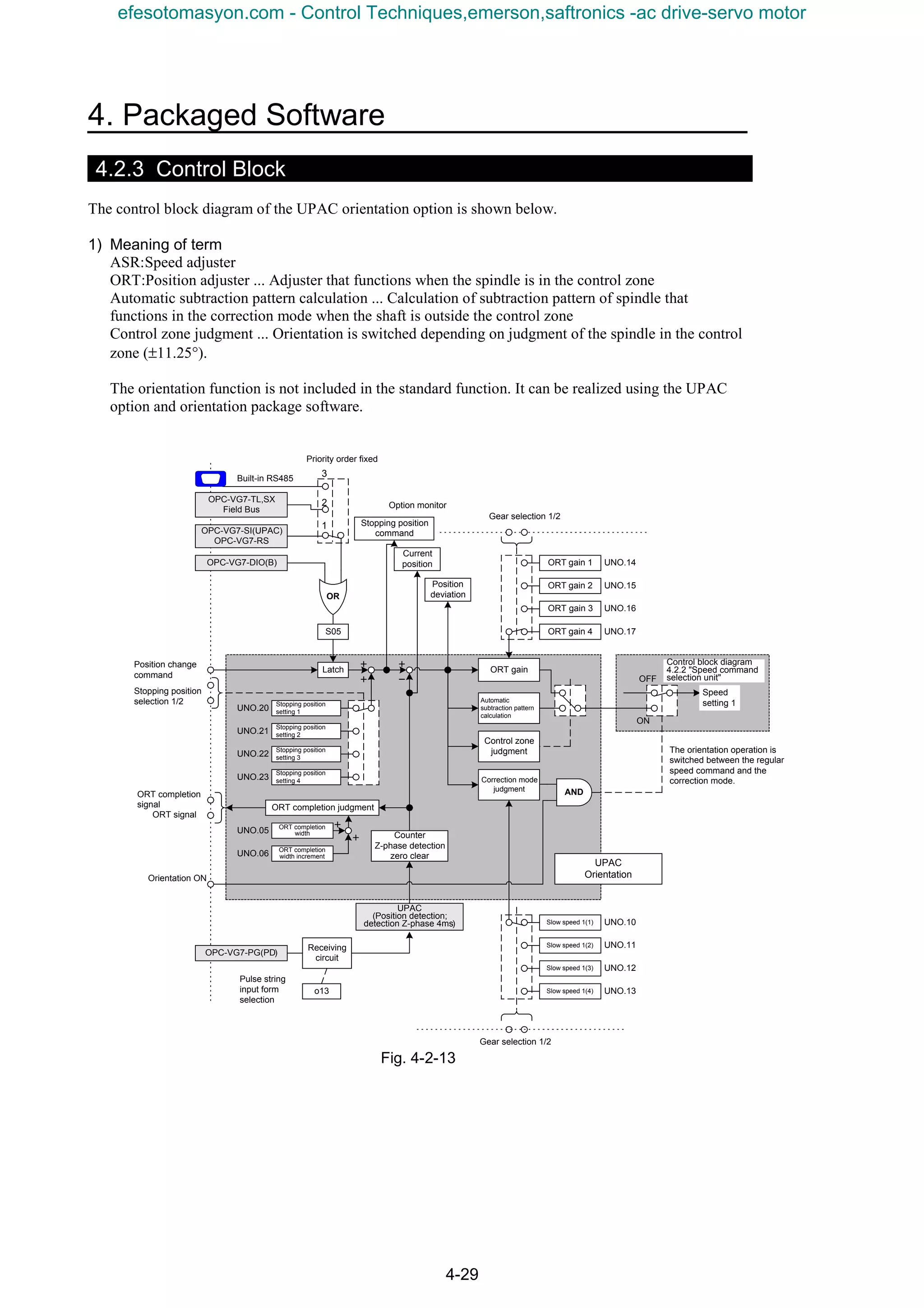
![4-30
4.2.4 Function Code
Table 4-2-7
Function
code
Name
LCD display
(Japanese)
Valid setting
range
Unit
Res
oluti
on
Initial
value
Change
during
operation
Remark
U01 ORT version information U01
USER
P1
- 1 1300□ No Read-only data. Shows version of UPAC package software.
U02
ORT rotation direction
from stopping
U02
USER
P2
0,1 - 1 0 No
0: Direction for shorter to target position.
1: Direction for following external slow speed direction.
Set to stop after shorter rotation or to follow slow speed direction
to conduct orientation when stopping.
U03
ORT stop mode
selection
U03
USER
P3
0,1 - 1 0 No
0: Stop in shortest time. (may accelerate)
1: Stop without accelerating from current speed
Set to accelerate over the second slow speed for orientation
operation or not.
U04 Control input selection U04
USER
P4
0,1,2 - 1 0 No
0: Internal terminal valid (X1 to X3)
1: DIOB card input valid
2: S05 (communication system such as T-link, RS485) valid
U05 ORT completion range U05
USER
P5
0-511 Pulse 1 0 Yes
0 to 511 pulses
Provides ORT completion signal (ON) when enters a range
specified by pulses set by parameter to the position for ORT
stopping.
U06
Completion range after
ORT stopping
U06
USER
P6
0-511 Pulse 1 0 Yes
0 to 511 pulses
After stop in ORT completion range, switch ORT completion
range to this value.
U07
ORT completion signal
ON timer
U07
USER
P7
0-1000 S 1 0 Yes
0 to 1000 (0.00 to 10.00 s)
Setting for timer after ORT completion to turning on ORT
completion signal.
U08
ORT completion signal
OFF timer
U08
USER
P8
0-1000 S 1 0 Yes
0 to 1000 (0.00 to 10.00 s)
Setting for timer after ORT completion release to turning off ORT
completion signal.
U09 Pulse encoder selection U09
USER
P9
-3-3 - 1 0 No
-3: 128P/R encoder -2: 256P/R encoder
-1: 512P/R encoder 0: 1024P/R encoder
1: 2048P/R encoder 2: 4096P/R encoder
3: 8192P/R encoder
U10 Slow speed 1 (1) U10
USER
P10
U11 Slow speed 1 (2) U11
USER
P11
U12 Slow speed 1(3) U12
USER
P12
U13 Slow speed 1(4) U13
USER
P13
0-1000 r/min 1 0 No
Set value for first slow speed (N1) during ORT
Four steps are available for setting. Use [RT1] and [RT2] for
switching these four steps.
U14 ORT gain (1) U14
USER
P14
U15 ORT gain (2) U15
USER
P15
U16 ORT gain (3) U16
USER
P16
U17 ORT gain (4) U17
USER
P17
0-1000 Times 1 0 Yes
0 to 1000 (0.0 to 100.0 times)
Position loop gain
Setting for position adjuster proportional gain during ORT.
Use [RT1] and [RT2] for switching these four steps.
Always assign [RT1] and [RT2] to X4 to X5 respectively.
U18 Reserved U18
USER
P18
- 1 0
U19 Reserved U19
USER
P19
- 1 0
Reserved
U20 Stop position setting 1 U20
USER
P20
U21 Stop position setting 2 U21
USER
P21
U22 Stop position setting 3 U22
USER
P22
U23 Stop position setting 4 U23
USER
P23
0-32768 - 1 0 No
Set the number of pulses of installed encoder × 4.
Set to 1024×4×100°÷360°=1138 for stop position command of
100° in forward direction when you use 1024p/r encoder.
Subtract one rotation when you set while exceeding four times.
Set the travel distance in shaft forward direction.
Use terminal input (switching stop position 1, 2) for changing
four-point stop position.
* Data switching is not accepted during ORT. Turn on the
position change command or temporarily turn off the ORT
ON signal.
U24
Speed detection
selection
U24
USER
P24
0,1 - 1 0 No
0: Integrated PG (PA, PB), PG (SD) card valid (SD prioritized)
P01="3": PMPG card valid for synchronous motor driving
1: PG (PD) card valid
U25
ORT speed just after
power on
U25
USER
P25
0-500 - 1 0 Yes
Speed limit function for orientation command from stop state just
after power on.
U64 ORT version information U64
USER
P64
- 1 1300□ No Read-only data. Shows version of UPAC package software.
(1) About setting range
• Though setting range from KEYPAD panel is –32768 to 32767, the UPAC limits the set values to
the above data range. For example, when you set ORT gain to –20, the UPAC limits it to 0, and
when you set ORT gain to 2000, the UPAC limits it to 1000.
About changing setting
(2) Though the function codes which are not changed during operation are not protected against input
from the KEYPAD panel, input are not reflected during operation.
(3) It takes about 0.06s to up the update UNO data. It takes 1 ms for the other function codes, F to o.
efesotomasyon.com - Control Techniques,emerson,saftronics -ac drive-servo motor](https://image.slidesharecdn.com/vg7upacmanual-140613044924-phpapp01/75/Vg7-upac-manual-174-2048.jpg)
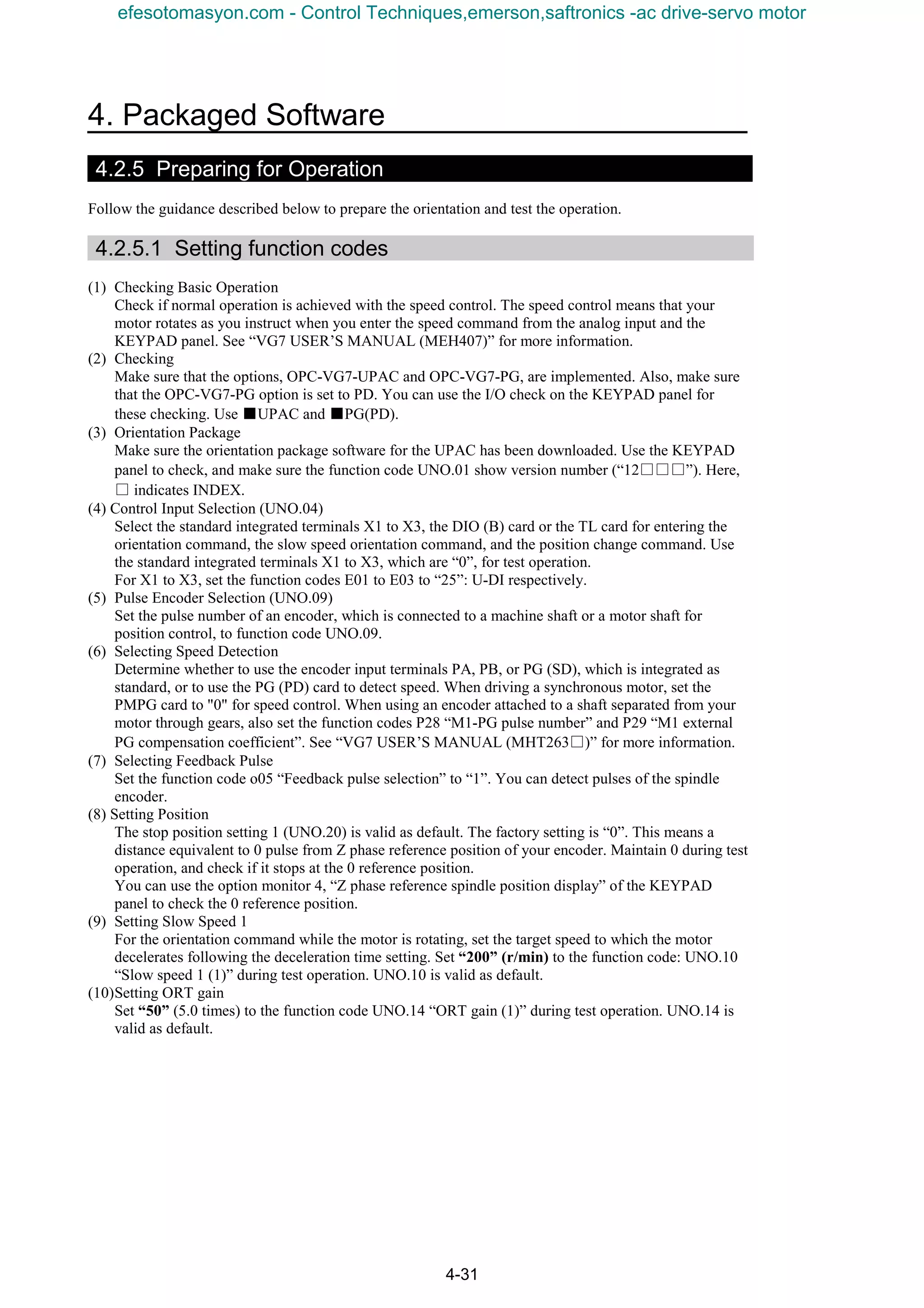
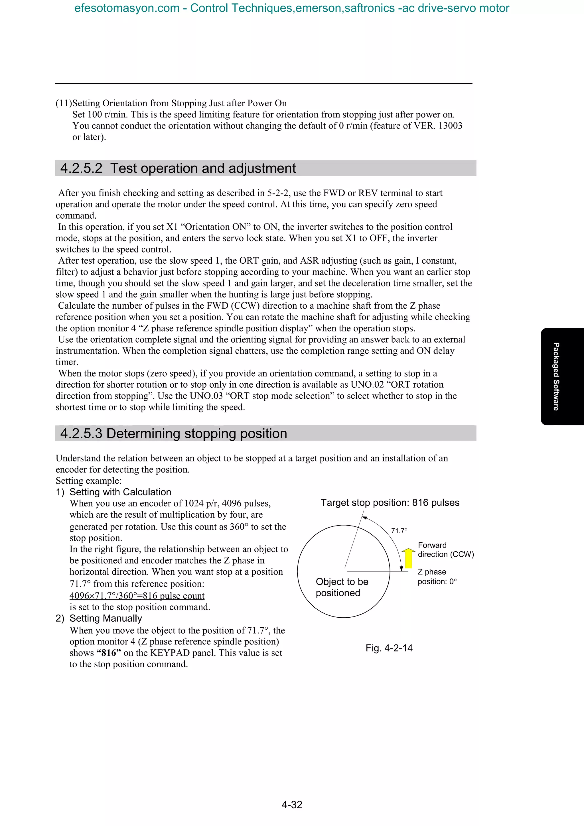
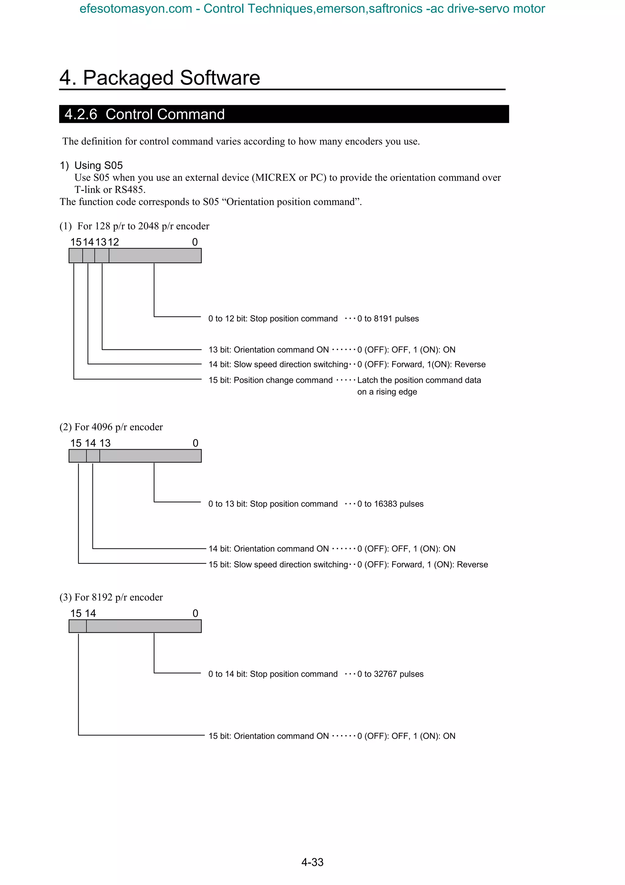
![4-34
2) Using General Input
Use general input when you use the general control terminals [X1] to [X3] to provide a control
command.
You can use the function code S06 “Operation command 1” to use [X1], [X2], and [X3] as S05
“Orientation position command” when the access is over the communication system (MICREX or PC).
When you enter control commands in both S05 and S06, they are “ORed”
15 5 4 3 2 10
2 bit [X1]: Orientation command on・・・・・・・ 0 (OFF): OFF, 1 (ON): ON
3 bit [X2]: Slow speed direction switching・・ 0 (OFF): Forward, 1 (ON): Reverse
4 bit [X3]: Position change command ・・ Latch the position command data
on a rising edge
3) Using DIO Card
You can use the 16-bit input of the DIOB when the OPC-VG7-DIO card is installed.
(1) For Encoder of 128 p/r to 2048 p/r
15141312 0
0 to 12 bit: Stop position command ・・・・・・ 0 to 8192 pulses
13 bit: Orientation command on・・・・・・・・・・ 0 (OFF): OFF, 1 (ON): ON
14 bit: Slow speed direction switching・・・・・ 0 (OFF): Forward, 1 (ON): Reverse
15 bit: Position change command ・・・・・・・・ Latch the position command data
on a rising edge
(2) For 4096 p/r encoder
15 14 13 0
0 to 13 bit: Stop position command ・・・・・・ 0 to 16383 pulses
14 bit: Orientation command ON ・・・・・・・・・ 0 (OFF): OFF, 1 (ON): ON
15 bit: Slow speed direction switching・・・・・ 0 (OFF): Forward, 1 (ON): Reverse
(3) For 8192 p/r encoder
15 14 0
0 to 14 bit: Stop position command ・・・・・・・ 0 to 32767 pulses
15 bit: Orientation command ON ・・・・・・・・・ 0 (OFF): OFF, 1 (ON): ON
efesotomasyon.com - Control Techniques,emerson,saftronics -ac drive-servo motor](https://image.slidesharecdn.com/vg7upacmanual-140613044924-phpapp01/75/Vg7-upac-manual-178-2048.jpg)
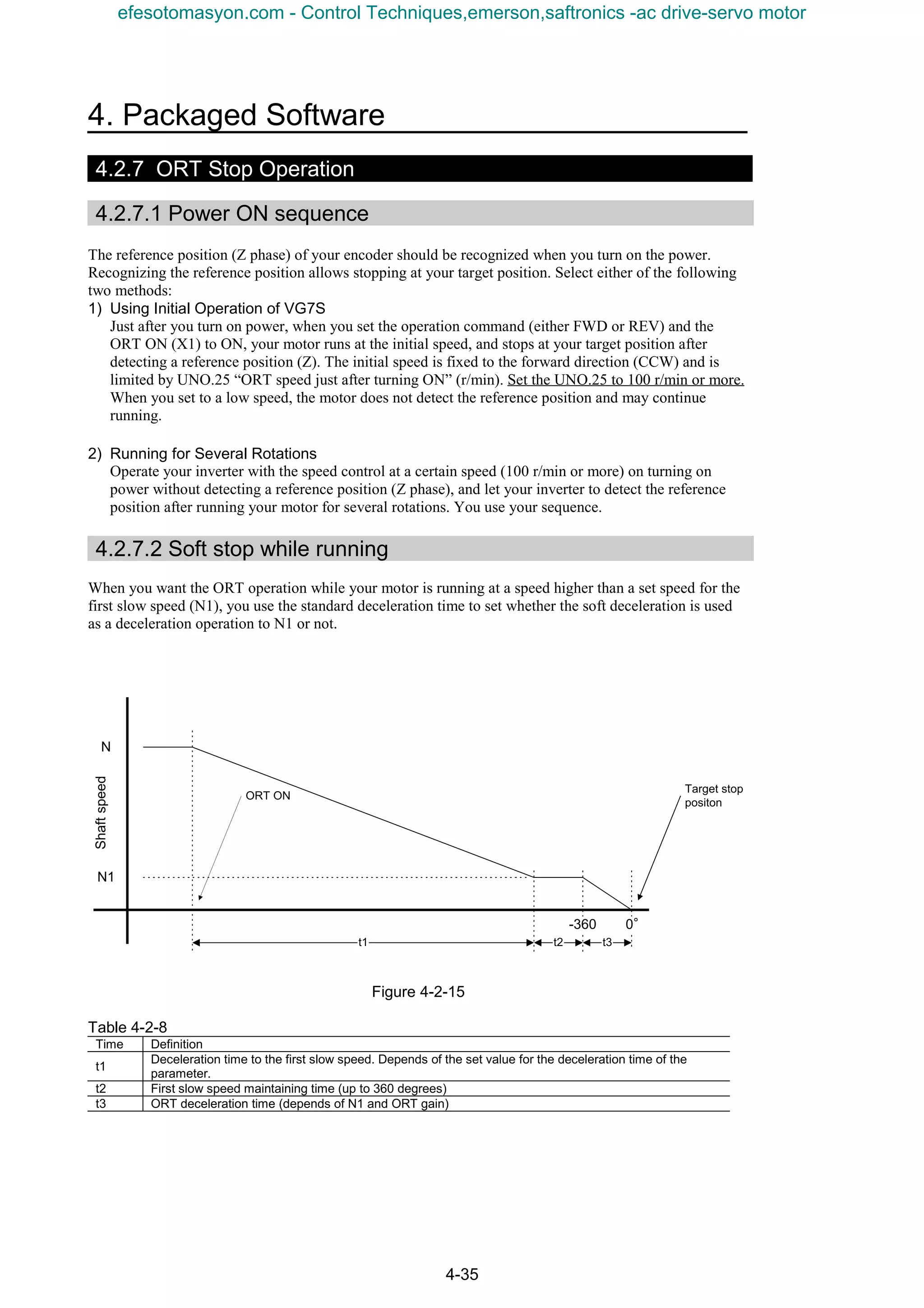
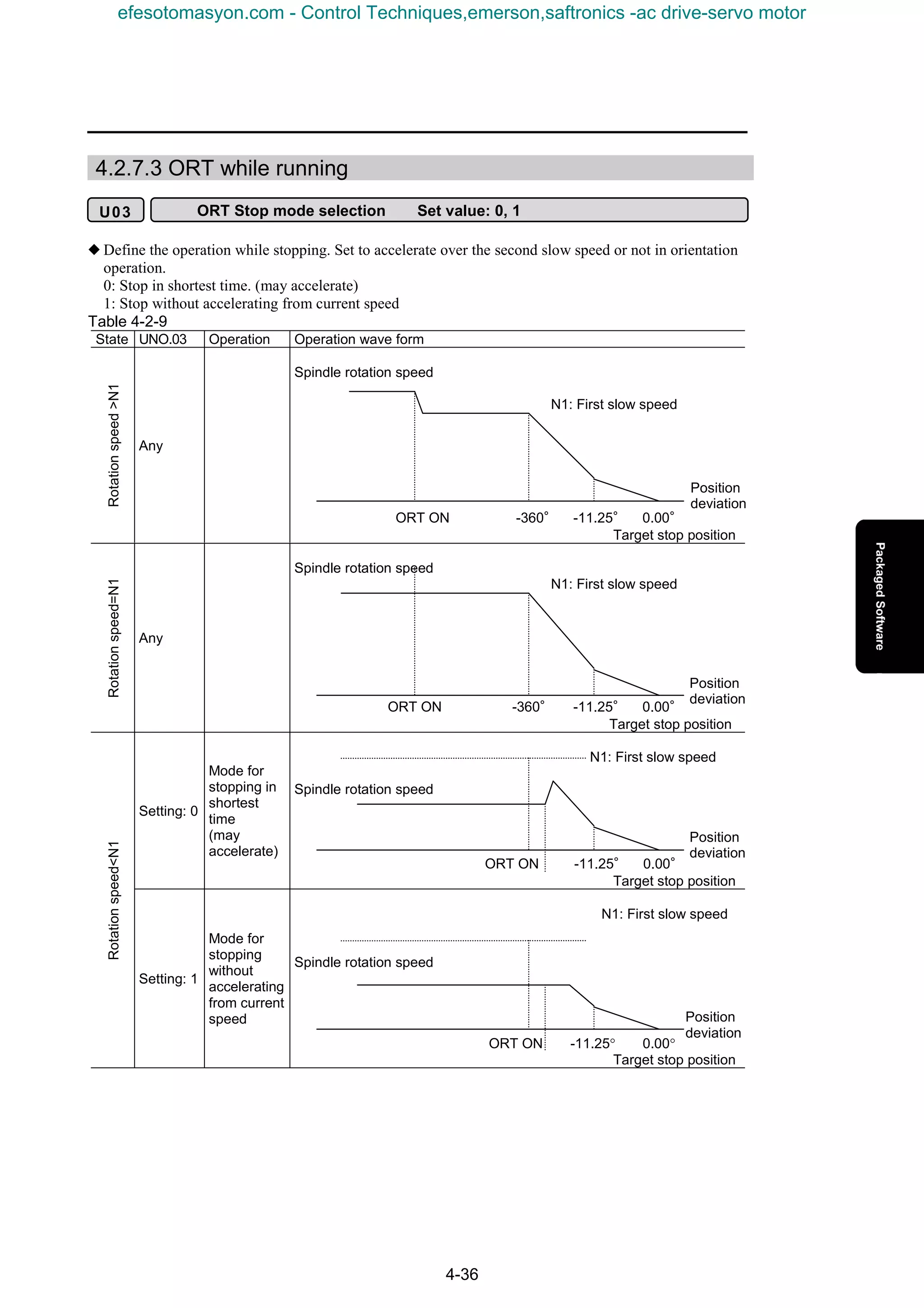
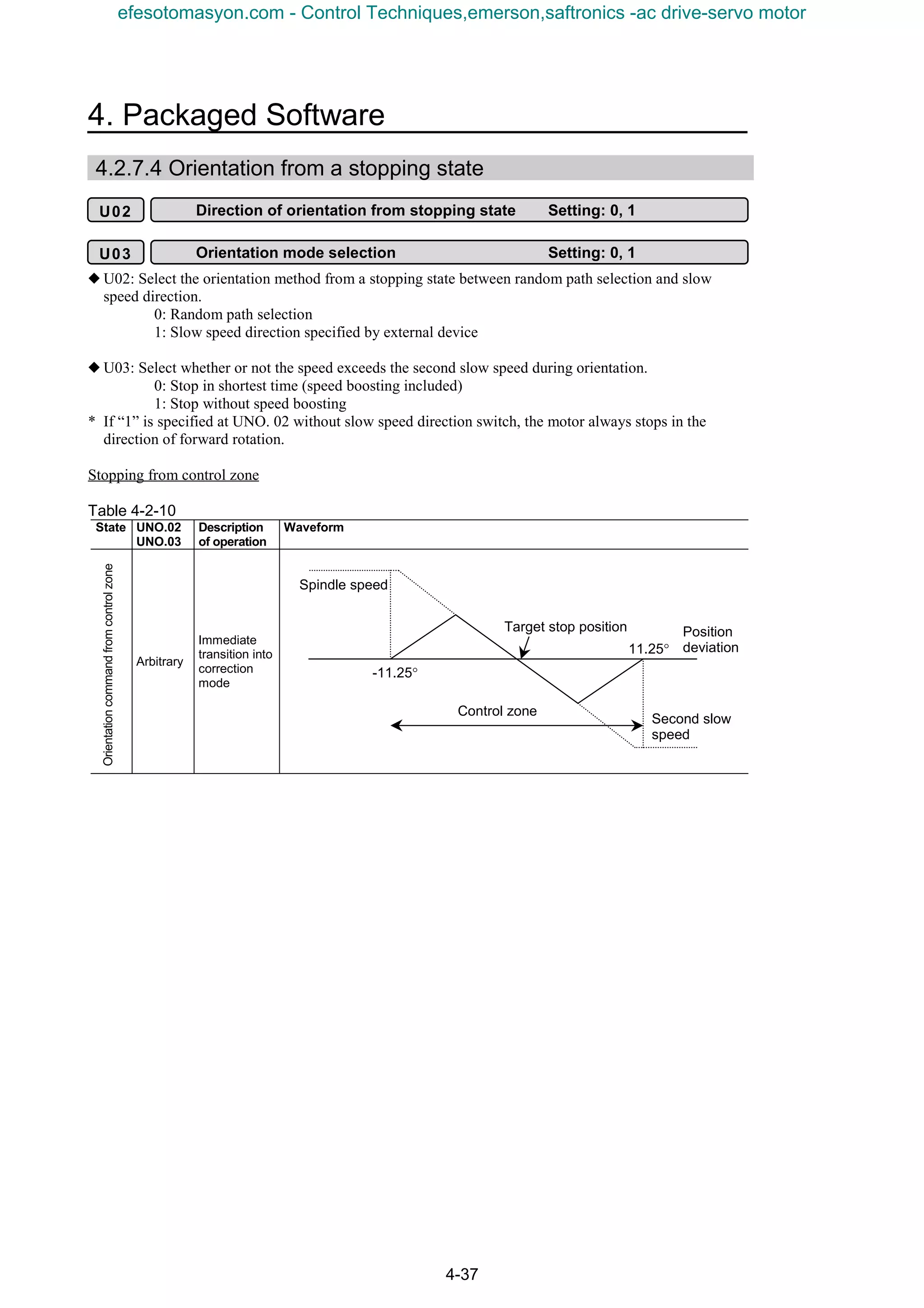
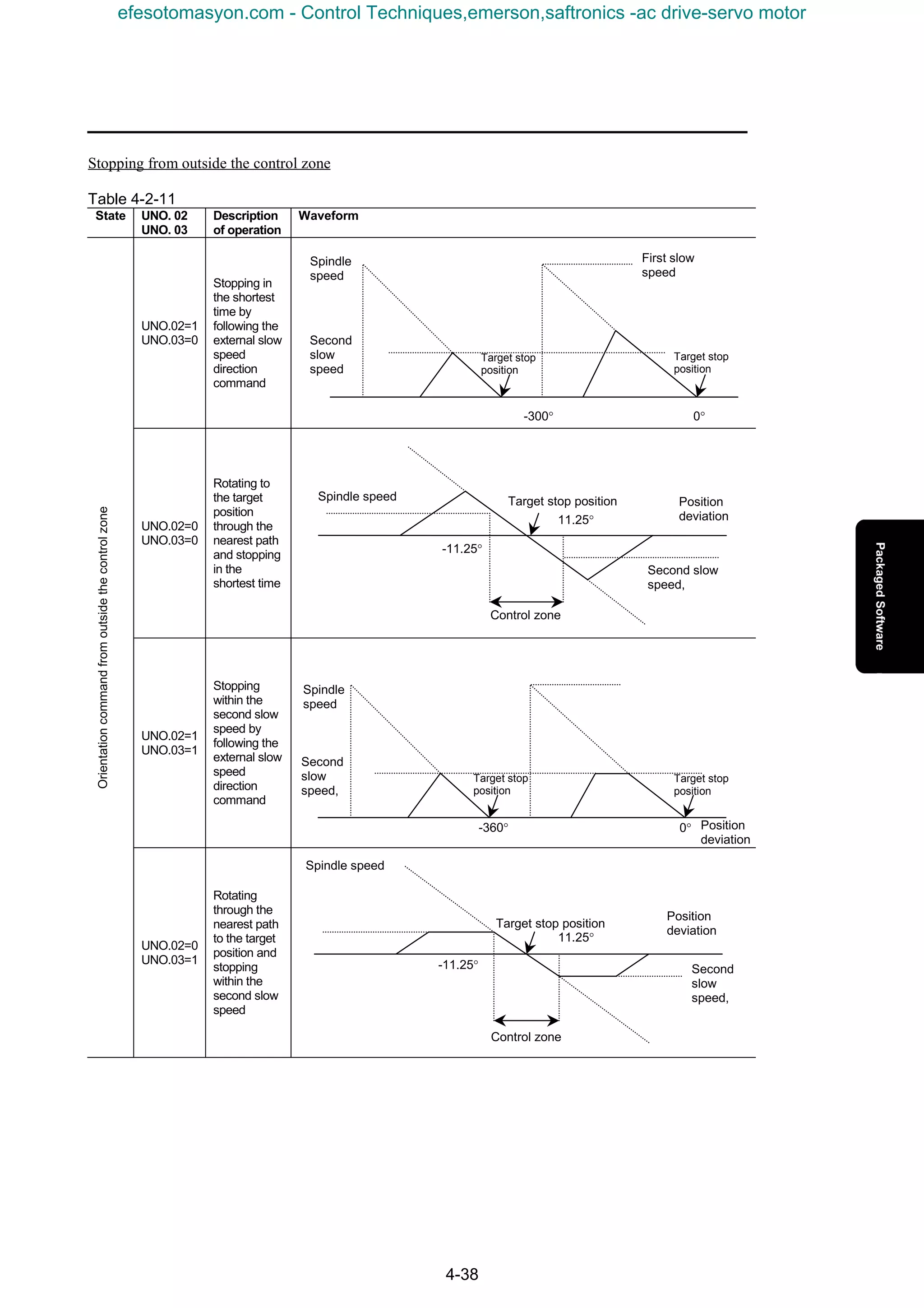
![4. Packaged Software
4-39
4.2.8 Input/Output Specification
4.2.8.1 Input signal
1) Control input
To use control inputs (orientation command, slow speed direction command, and position change
command) at general-purpose input terminals, assign the [X1], [X2] or [X3] terminal to universal DI.
2) Gear selection
Use [RT1] and [RT2] of standard functions to switch.
3) Stopping position selection
Assign [X6] and [X7] to universal DI to use the terminals for stopping position selection.
Table 4-2-12
Terminal Name of command Assignment Description
[X1]
Orientation command
(ORT ON)
Orientation signal
ON (1): Orientation
OFF (0): No orientation; regular operation
[X2]
Slow speed direction
command
Signal for designating the direction of rotation to reach the target
stopping position during orientation from a stopping state.
ON (1): Reverse rotation
OFF (0): Forward rotation
[X3]
Position change
command
Universal DI
Signal for latching data after a change in the external stop position
command
Rising edge (hold for at least 10 ms): Read external position command
[X4]
Gear selection 1
Selection between
acceleration /
deceleration and ASR
[X5]
Gear selection 2
Selection between
acceleration /
deceleration and ASR
[X4], [X5] = OFF, OFF → Acceleration / deceleration, ASR, ORT
gain, slow speed 1 valid
[X4], [X5] = ON, OFF → Acceleration / deceleration, ASR, ORT
gain, slow speed 2 valid
[X4], [X5] = OFF, ON → Acceleration / deceleration, ASR, ORT
gain, slow speed 3 valid
[X4], [X5] = ON, ON → Acceleration / deceleration, ASR, ORT gain,
slow speed 4 valid
[X6] Stopping position
selection 1
[X7] Stopping position
selection 2
Universal DI
[X6], [X7] = OFF, OFF → UNO. 20 stopping position setting 1 valid
[X6], [X7] = ON, OFF → UNO. 20 stopping position setting 2 valid
[X6], [X7] = OFF, ON →UNO. 20 stopping position setting 3 valid
[X6], [X7] = ON, ON → UNO. 20 stopping position setting 4 valid
[X8]
[X9]
Arbitrary
Fig. 4-2-16
Operation
command
Orientation command
Orientation completion
During orientation
Motorspeed
Time
Stop position command A Stop position command B Stop position command C Stop position command D
Motorspeed
Orientation command
Operation
command = ON
Slow speed direction command
Position change command
At least 10ms
Failure to operate
because of no change
in position
Orientation mode
Servo lock
Reverse rotation in slow
speed direction
A B C D
efesotomasyon.com - Control Techniques,emerson,saftronics -ac drive-servo motor](https://image.slidesharecdn.com/vg7upacmanual-140613044924-phpapp01/75/Vg7-upac-manual-183-2048.jpg)
![4-40
4.2.8.2 Output signal
The orientation completion signal and orientation signal can be output.
The off-delay and on-delay timers for these outputs can be specified.
These settings do not give effects on the positioning accuracy.
Table 4-2-13
Terminal Name of signal Assignment Description
[Y1] Orientation completion signal ON upon completion of orientation
[Y2] Orientation signal
Universal DO
[U-DO] ON during orientation
Specify the completion signal using the completion width setting function code.
Table 4-2-14
Name of parameter,
No.
Name Indication on keypad panel
Setting
range
Description of setting
UNO. 05
Orientation
completion
width
USER P05
0
to
511
0 to 511 pulses
The orientation completion signal is
output if the stop position after
orientation is within the pulse specified
as the target stop position with this
parameter.
UNO. 06
Completion
width after
orientation
USER P06
0
to
511
0 to 511 pulses
The orientation completion width is
replaced with this setting after stoppage
within the orientation completion width.
4.2.8.3 Output delay operation
Table 4-2-15
Name of parameter
No.
Name Indication on keypad panel
Setting
range
Description of setting
UNO. 07
Orientation
completion
signal
activation
timer
USER P07
0
to
1000
0 to 1000 (0.00 to 10.00s)
Timer setting of interval from completion
of orientation to issuance of orientation
completion signal
UNO. 08
Orientation
completion
signal
deactivation
timer
USER P08
0
to
1000
0 to 1000 (0.00 to 10.00s)
Timer setting of interval from cancellation
of orientation completion to deactivation
of orientation completion signal
(1) During regular operation
Fig. 4-2-17
Orientation
command
Orientation signal
Orientation
completion signal
Orientation
command
Orientation signal
Orientation
completion signal
Stopping in orientation
completion width
Stopping in orientation
completion width
Orientation completion signal
activation timer setting
Orientation completion signal
activation timer setting
Orientation completion signal
deactivation timer setting
(2) If the orientation signal is turned off
efesotomasyon.com - Control Techniques,emerson,saftronics -ac drive-servo motor](https://image.slidesharecdn.com/vg7upacmanual-140613044924-phpapp01/75/Vg7-upac-manual-184-2048.jpg)
![4. Packaged Software
4-41
4.2.8.4 Option monitor
Three types of data can be referred to from the keypad panel installed on the inverter.
Table 4-2-16
Option
monitor
Description of
indication
Data range Description
Option
monitor 3
Stopping position
command
Positive value
0 to 32767
Valid data of the stopping position setting
(internal + external) is displayed. For the
conversion method of the displayed data, refer
to the column below.
Option
monitor 4
Datum shaft
position in Z-phase
Positive value
0 to 32767
The position in the forward direction (counter-
clockwise rotation) from the Z-phase datum is
displayed.
The angle of rotation of the shaft in reference to
the direction of rotation is displayed in pulses.
To convert the data into degrees, follow the
description below.
Option
monitor 5
Position deviation
variable
(Internal stopping
position command
- current position)
Positive or negative
value
-500 to 500 pulses
-500 to 500
The deviation variable is displayed in the positive
or negative value.
Positive: If there is deviation in the forward
direction, reverse rotation reduces the deviation
to zero.
Negative: If there is deviation in the reverse
direction, forward rotation reduces the deviation
to zero.
(“0” is displayed for values exceeding +/-500.)
4.2.8.5 Gear selection
If a speed reduction means is installed between the motor and the shaft, the first slow speed, speed control
adjustment (gain, integration constant, etc.), position control gain (orientation gain), and S-curve
acceleration / deceleration time can be switched in four steps according to the gear ratio, using digital
inputs [RT1] and [RT2].
Table 4-2-17
Digital input
Effective functions
[RT2] [RT1]
Slow speed 1 Speed control
Position
control
Acceleration /
deceleration
time
S-curve setting
OFF OFF
Slow speed
1 (1)
ASR1-P (gain)
ASR1-I (integration constant)
ASR1-FF (gain)
ASR1 input filter
ASR1 detection filter
ASR1 output filter
Orientation
gain 1
Acceleration
time 1
Deceleration
time 1
S-curveacceleration onstartingside 1
S-curveacceleration onarrivalside1
S-curvedeceleration onstartingside1
S-curvedeceleration arrival side 1
OFF ON
Slow speed
1 (2)
ASR2-P (gain)
ASR2-I (integration constant)
ASR2-FF (gain)
ASR2 input filter
ASR2 detection filter
ASR2 output filter
Orientation
gain 2
Acceleration
time 2
Deceleration
time 2
S-curve on starting side 2
S-curve on arrival side 2
ON OFF
Slow speed
1 (3)
ASR2-P (gain)
ASR2-I (integration constant)
ASR2-FF (gain)
ASR2 input filter
ASR2 detection filter
ASR2 output filter
Orientation
gain 3
Acceleration
time 3
Deceleration
time 3
S-curve on starting side 3
S-curve on arrival side 3
ON ON
Slow speed
1 (4)
ASR2-P (gain)
ASR2-I (integration constant)
ASR2-FF (gain)
ASR2 input filter
ASR2 detection filter
ASR2 output filter
Orientation
gain 4
Acceleration
time 4
Deceleration
time 4
S-curve on starting side 4
S-curve on arrival side 4
The function for damping the shock during switching (C70: ASR switching time) can be used.
efesotomasyon.com - Control Techniques,emerson,saftronics -ac drive-servo motor](https://image.slidesharecdn.com/vg7upacmanual-140613044924-phpapp01/75/Vg7-upac-manual-185-2048.jpg)
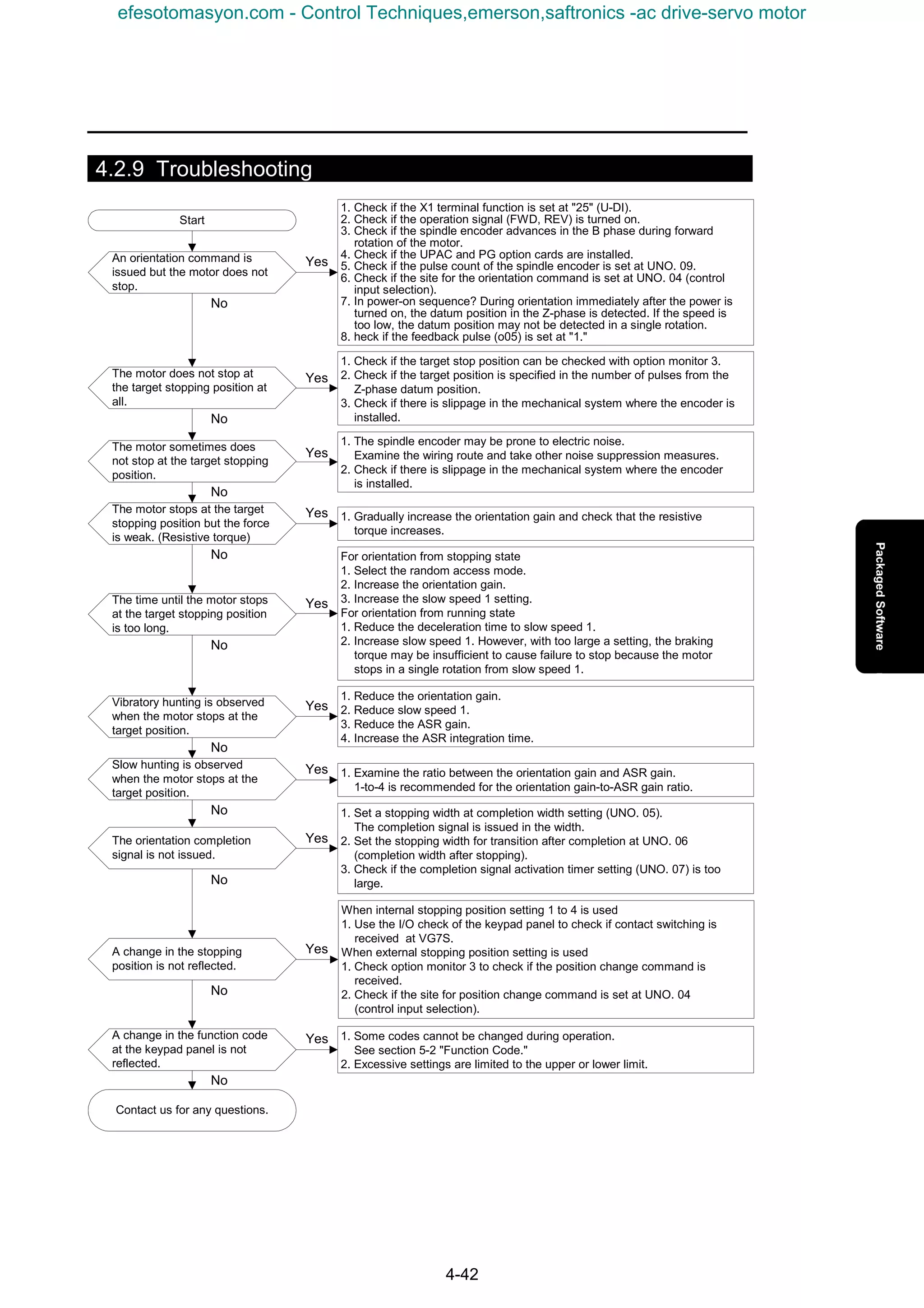
![4. Package Software
4-43
4.3 WPS-VG7-TEN
WPS-VG7-TEN is package software for tension control designed for a winding system.
(Windows Personal Computer Software Package-Tension control system on VG7S)
The feature of the package includes:
- Constant tension torque control with tension pickup detection
- Wound diameter calculation using a line speed command and winding motor speed
-Tension taper calculation
- Automatic sampling for mechanical torque by automatically measuring mechanical loss
- Interface for a POD or a PLC for setting tension, taper and various conditions. (Note that you need an additional
option card for interface)
This package software is provided for free on the CD-ROM for WPS-VG7-PCL (loader software). We would like
you to agree the following terms and conditions before you use this package to build your system.
[Terms of Agreement]
We would like you to agree the following confirmation terms.
Otherwise you should not use the WPS-VG7-TEN package software.
If you need information on the agreement, please contact our sales representative.
(1) When you use the analog interface to build your system, you should consult the "VG7 User's Manual" and
apply sufficient measures for preventing noise.
(2) All function codes U01 to 64 for tension control are set to '0' on delivery. For parameters you want to change
their values, you set these values.
(3) The battery included in the UPAC is used to back up the data. The lifetime of the battery is five years (at
25°C). When the atmospheric temperature for the power supply you use is high, the lifetime of the battery
becomes shorter than five years. When the lifetime of the battery expires, the UPAC alarm "ErA" shows up,
and an end user should be ready for immediately replacing the battery. Please refer to the appropriate section
described on the UPAC in the "VG7 User's Manual" for replacing the battery.
(4) Review and adjust your machine system when the machine system presents noise/vibration due to resonance or
backlash of gears. When you cannot adjust the machine system to restrain them, you should employ
electrical measures, and you should adjust the standard functions of the VG7, the gain and integration time of
the PID controller, and the parameters for the filter while you separate the inverter from the floor. Please
note that we cannot provide measures for adding dedicated control applications for the control of your UPAC
or VG7.
(5) It is not allowed by the copyright law to duplicate, rent or resell the entire or a part of the program.
(6) There is no limitation/restriction on adding, altering, or deleting the specification to develop your own program
based on this tension control program. We will provide technical support and consultation on developing
programs.
(7) Fuji is not responsible for direct or indirect damages caused by the program itself of WPS-VG7-TEN or
alteration, addition, or deletion made to the program by a customer.
I agree the terms above (Your signature here)
efesotomasyon.com - Control Techniques,emerson,saftronics -ac drive-servo motor](https://image.slidesharecdn.com/vg7upacmanual-140613044924-phpapp01/75/Vg7-upac-manual-187-2048.jpg)
![4-44
4.3.1 System Consideration
4.3.1.1 Specifications
Table 4-3-1
Item Tension Control Specification
Option card type You need the OPC-VG7-UPAC and an additional card for interface.
Package software Tension control package. Version number "1200 " (Use function code UNo.64 for
display.)
Control type Constant tension PID control with a tension pick up: ATR (Auto Tension Regulator)
Input signal
[Ai1]: Tension detection signal 0 V to 10 V
[Ai2]: Line speed input 0 V to 10 V
Analog
Output
signal
[Ao1]: -10 V to 0 V to 10V
[Ao2]: -10 V to 0 V to 10V
[Ao3]: -10 V to 0 V to 10V
When defined as U-Ao, you can monitor the
following output.
1. Tension setting [N]
2. ATR correction [N]
3. Wound diameter [mm]
4. Torque corresponding to tension command
[%]
5. Acceleration/deceleration torque [%]
6. Mechanical loss torque [%]
Input signal
[X1]: Cancel torque command (CCL)
[X2]: ON on operation command (U-Di)
[X3]: OFF on stop command (U-Di)
[X4]: ON on tension ON command (U-Di)
[X5]: OFF on emergency stop (U-Di)
[X6]: Alarm reset (U-Di)
[X7]: Mechanical loss measuring command (U-Di)
[X8]: Reset wound diameter (U-Di)
[X9]: Coast-to-stop
Digital
Output
signal
[Y1]: ON on abnormal tension (U-Do)
[Y2]: Completion of mechanical loss measuring (U-Do)
[Y5]: ON on inverter error (U-Do)
Other
Set from POD, T-Link, or
KEYPAD panel
[U01]: Stall tension setting 0 - [N]/0 -
[U02]: Operation tension setting 0 - [N]/0 -
[U03]: Material thickness - [mm]/ - ×1000
[U04]: Material width - [mm]/ -
[U05]: Abnormal tension (Upper limit setting) 0 - 150[%]/0 - 150
[U06]: Abnormal tension (Lower limit setting) 0 - 150[%]/0 - 150
[U07]: Wound diameter (Initial value) 100 - 1500 [mm]/100 - 1500
[U08]: Material mass 500 - 2000 [kg/m3
]/500 - 2000
[U09]: Linear taper setting 0 - 150[%]/0 - 150
[U10]: Two-point taper setting 0 - 150[%]/0 - 150
[U11]: Two-point taper diameter setting 0 - 2000[mm]/0 - 2000
- When you use the POD to set the data, use an option card (OPC-VG7-RS: RS 485 extension card).
Though you can connect the POD to the integrated RS485, you need the extension card when you are
using the integrated RS485 for another application.
- When you use the PLC to set the data, use an option card (OPC-VG7-TL: T-Link I/F card).
TTTT
DmaxDmaxDmaxDmax
[mm][mm][mm][mm]
設定張力設定張力設定張力設定張力
[kg][kg][kg][kg]
DminDminDminDmin
[mm][mm][mm][mm]
【U10】%【U10】%【U10】%【U10】%
【U11】mm【U11】mm【U11】mm【U11】mm
【U09】%【U09】%【U09】%【U09】%
Set tension
[kg]
Dmin
[mm]
Dmax
[mm]
[U11] mm
[U10] %
[U09] %
T
efesotomasyon.com - Control Techniques,emerson,saftronics -ac drive-servo motor](https://image.slidesharecdn.com/vg7upacmanual-140613044924-phpapp01/75/Vg7-upac-manual-188-2048.jpg)
![4. Package Software
4-45
4.3.2 Input/Output Standard Interface (single inverter is used)
1) Bit Signal from Control Panel to UPAC POD address
(1) Tension command (ON on ON) %IX1.5.5 X4 Hardware/T-link/POD 401799-5
(2) Operation command
(ON on command) %IX1.5.3 X2 Hardware/T-link/POD 401799-3
(3) Stop command (OFF on stop) %IX1.5.4 X3 Hardware/T-link/POD 401799-4
(4) Emergency stop
(OFF on emergency stop) %IX1.5.6 X5 Hardware only
(5) Alarm reset (ON on reset) %IX1.5.7 X6 Hardware/T-link/POD 401799-7
(6) Mechanical loss automatic measuring command
(ON while command is active) %IX1.5.8 X7 Hardware/T-link/POD 401799-8
(7) Wound diameter reset (ON on reset) %IX1.5.9 X8 Hardware/T-link/POD 401799-9
2) Bit Signal from UPAC to Control Panel
(1) Inverter error (ON on error) %QX1.23.4 Y5 Relay output Hardware 401799-5
(2) Abnormal tension
(ON on abnormality) %QX1.23.0 Y1 Transistor output Hardware 401799-0
(3) Completion of measuring mechanical loss (ON for two seconds after completion)
%QX1.23.1 Y2 Transistor output Hardware 401799-1
3) Data Setting from POD and Control Panel to UPAC
(1) Line speed command Ai2 DC 0 - n V/0 - n m/min
(2) Tension feedback signal input Ai1 DC 0 – 10 V/0 - n N
(3) Stall tension setting [N] 0 - n N USER P1 POD 402818
(4) Operation tension setting [N] 0 - n N USER P2 POD 402819
(5) Abnormal tension setting
(Upper limit level) [N] 0 - n N USER P5 POD 402822
(6) Abnormal tension setting
(Lower limit level) [N] 0 - n N USER P6 POD 402823
(7) Initial wound diameter setting [mm] n - n mm USER P7 POD 402824
(8) Material width [mm] n - n mm USER P4 POD 402821
(9) Material thickness [mm] n - n mm (1000=1 mm) USER P3 POD 402820
(10) Material specific gravity (density) [kg/m3
] n - n kg/m3
USER P8 POD 402825
(11) Taper
Linear taper setting [%] 0 - n % USER P9 POD 402826
‚ Two-point taper setting [%] 0 - n % USER P10 POD 402827
ƒ Two-point taper diameter setting [mm] n - n mm USER P11 POD 402828
Tension
T
R [%] Q [%]
DS [mm]
Wound diameter
DmaxDmin
[Taper setting]
Tension set to (100-Q)%
(12) Load cell input 0 - n N USER P50 POD 402867
(13) Speed monitor 0 - n m/min(1000=100m/min) USER P49 POD 402866
efesotomasyon.com - Control Techniques,emerson,saftronics -ac drive-servo motor](https://image.slidesharecdn.com/vg7upacmanual-140613044924-phpapp01/75/Vg7-upac-manual-189-2048.jpg)
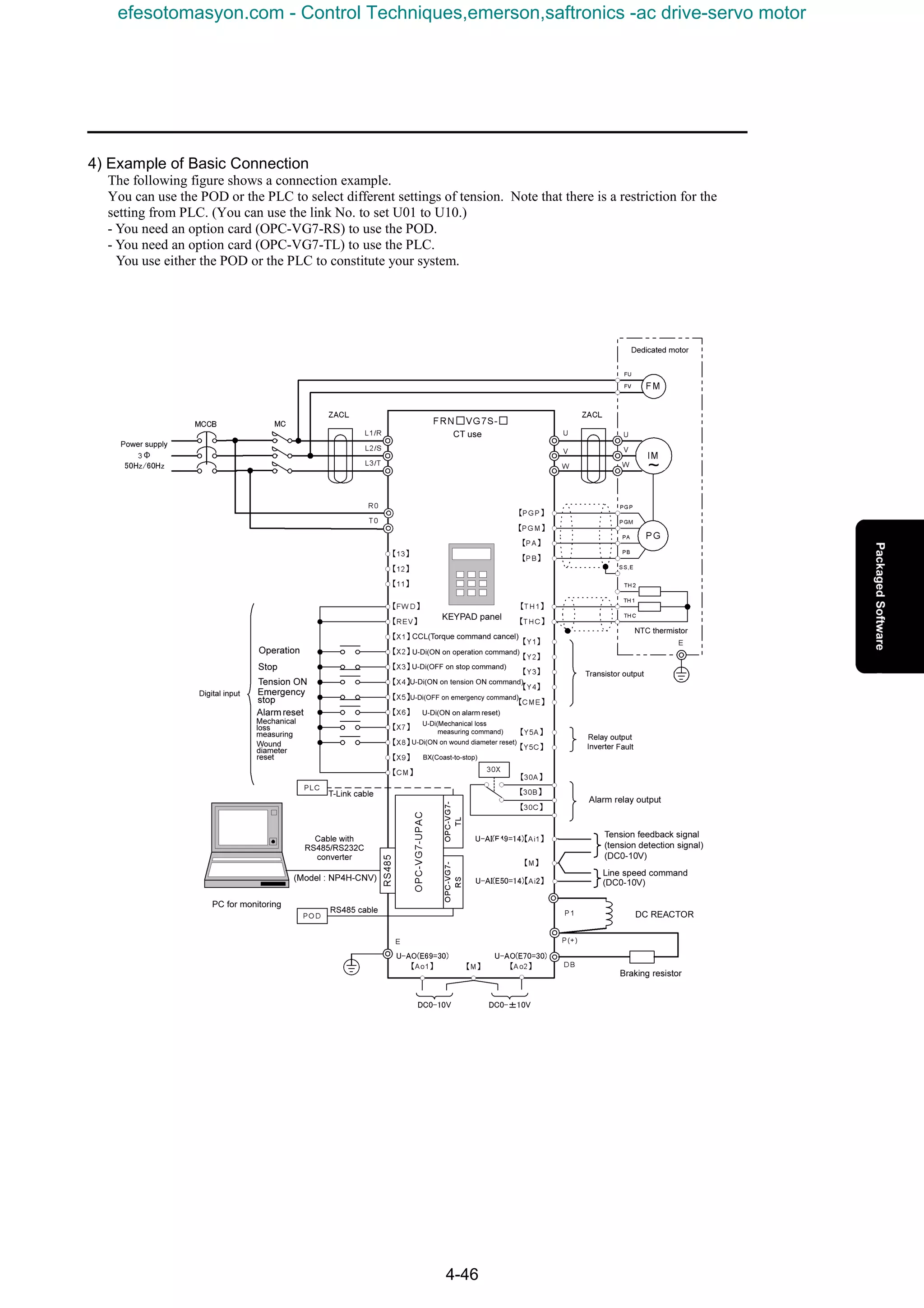
![4. Package Software
4-47
4.3.3 How to Adjust
Follow the steps below for adjusting.
1) Mechanical Loss Automatic Measuring
You can use the mechanical loss automatic measuring command to measure torques necessary for loads at
individual rotations of your motor, and store the data into the software. (Required time for the automatic
measuring is about eight minutes.)
<Mechanical conditions>
- Operate while a paper tube is attached. (Raw material is not required.)
<Mechanical loss measuring>
- Operate at the maximum motor rotation speed determined by the maximum line speed, the minimum wound
diameter and the speed reduction ratio.
- The rotation speed is automatically measured at 20 points while the speed is reduced stepwise.
- After the mechanical loss is measured, the motor accelerates to the maximum rotation speed again to
automatically measure the acceleration torque. It is dangerous, and you should watch for eight minutes until the
measuring is completed. Keep away from your winding machine.
2) Set/Check Fixed Constants
- Start the UPAC and check the constants. (o38: "1" or "2")
- To prevent a malfunction, reset the I/O definition for UPAC=>INV.
[Uncheck the check marks for the individual output in the I/O group setting in System_Definition. (Record the
existing setting for later recovery.)]
(1) Dedicated Software for Winding Machines
The current software is configured for a winding machine.
(2) I/O Check
- Experimentally apply external DI's, and use the online monitor of the UPAC to check their state.
- Use the online monitor of the UPAC to check whether external analog inputs are received as correct values.
(3) Checking Individual Constants
Check ifinput values set by using the user parameters are received in the UPAC as correct values.
If you can experimentally provide the tension command value and the like, check the calculated torque value.
3) Adjusting Control Parameters
- Conduct individual adjusting with an actual operation while raw material is mounted.
- Set the I/O definition for UPAC=>INV.
[Uncheck the check marks for the individual output in the I/O group setting in System_Definition. (Record the
existing setting for later recovery.)]
(1) Setting Individual Conditions
Set the subjects to adjusting: U01, U02, U03, U04, U05, U06, U07, U08, U09, U10, U11, U12, U13, U14,
U15, U27, U28, U31, and U48.
Acceleration/deceleration time: F07 and F08 (Set the times to reach the speeds described above, and set the
pitch of rising speed. Note that set the same values as the rising/falling of the line speed.)
(2) Tension Control (PID) Parameters
Base parameters for the tension control.
Subjects to adjusting: U20, U21, U25, U26, U29, U30, U44, and U56 to U61
Proportional term (P): U17 and U22
Integral term (I): U18 and U23
Differential term (D): U19 and U24
Adjust tension control parameters during the stall operation.
‚ Adjust slack on start.
Adjust what corresponds to dynamic mechanical loss torque.
Set U38, U39, U45, and U46.
ƒ Adjust the tension control parameters at a constant speed.
„ Adjust the acceleration/deceleration compensation torque.
Conduct a line operation after adjusting the stall tension, and adjust while increasing/decreasing the speed.
Set U33, U34 to U42, U45 to U48, U62, and U63.
efesotomasyon.com - Control Techniques,emerson,saftronics -ac drive-servo motor](https://image.slidesharecdn.com/vg7upacmanual-140613044924-phpapp01/75/Vg7-upac-manual-191-2048.jpg)
![4-48
4.3.4 Parameter Description
1) Functions for Setting Tension and Material Conditions
Sets the tension setting value while stalling. (Stall tension is present while the tension is ON and the operation
command is OFF.)
Sets the tension set value while operating. (Operation tension is present while the tension is ON and the operation
command is ON.)
2) Functions Relevant to Setting Material Conditions
When these set values are exceeded, a signal for stopping the line operation is provided externally, and the winding
machine stops.
Sets the initial wound diameter of the winding machine.
Enter a mass per 1 m3
in [kg].
Sets for calculating the acceleration/deceleration torque. (Used for GD2
conversion corresponding to the material)
3) Taper Setting
See the figure below.
See the figure below.
See the figure below.
U01 Stall tension setting Set value: 0 - 980/0 - 980 [N] (without limiter)
U02 Operation tension setting Set value: 0 - 980/0 - 980 [N] (without limiter)
U03
Material thickness setting Set value: 1 - 30000/0.001 - 30 [mm]
(without limiter)
U04
Material width setting Set value: 100 - 1000/100 - 1000 [mm]
(without limiter)
U05
Abnormal tension (Upper limit setting) Set value: 0 - 1960/0 - 1960 [N]
(without limiter)
U06
Abnormal tension (Lower limit setting) Set value: 0 - 1960/0 - 1960 [N]
(without limiter)
U07
Wound diameter (Initial value) Set value: 100 - 1500/100 - 1500 [mm]
(without limiter)
U08
Material mass Set value: 500 - 2000 /500 - 2000 [kg/m3
]
(without limiter)
U10 Two-point taper setting Set value: 0- 150/0 - 150 [%] (without limiter)
U09 Linear taper setting Set value: 0 - 150/0 - 150 [%] (without limiter)
U11
Two-point taper diameter setting Set value: 0 - 2000/0 - 2000 [mm]
(without limiter)
T
Dmax
U10
U11
Tension[N]
Dmin
Wound
diameter
[mm ]
U09 %
%
Set tension value at the
maximum diameter:
T (100-U09)÷÷÷÷100[N]
U12
U28
×
φ
efesotomasyon.com - Control Techniques,emerson,saftronics -ac drive-servo motor](https://image.slidesharecdn.com/vg7upacmanual-140613044924-phpapp01/75/Vg7-upac-manual-192-2048.jpg)
![4. Package Software
4-49
4) Tension Conditions Setting
Enter the minimum value for the coil diameter. (Enter the bobbin diameter.)
Enter the maximum tension for scale conversion for the tension detection value.
Use N for entry.
Enter × 100.
Enter the maximum tension set value for scale conversion for the tension set value.
Use N for entry. (Enter kg × 9.8.)
5) Functions Relevant to Detecting Tension
These are terms set for the feed back control for a difference between the instructed tension and the detected
tension.
A proportional operation (P), an integral operation (I), and a differential operation (D) of the ATR as a control
type for eliminating a difference between a measured value and a reference value are used for a highly precise
tension feed back control.
Fixed to the PID control type described in the figure below.
P regulator
ATR output
Tension
feedback
U16=0::::PID Type
ATR output =(ATR-P)+(ATR-I)+(ATR-D)
I regulator
D regulator
Motor rotation speed
Machine shaft rotation speed
U14 Speed reduction ratio Set value: 0 - 10000/0 - 100.00 (without limiter)
U12
Coil diameter (Minimum diameter) Set value: 100 - 2000/100 - 2000 [mm]
(without limiter)
U13
Range setting for maximum value for tension detection value
Set value: 0 - 14700/0 - 1470 [N] (without limiter)
U15
Range setting for maximum tension set value Set value: 0 - 9800/0 - 980 [N]
(without limiter)
U16 PID control type selection Set value: Fixed to 000
efesotomasyon.com - Control Techniques,emerson,saftronics -ac drive-servo motor](https://image.slidesharecdn.com/vg7upacmanual-140613044924-phpapp01/75/Vg7-upac-manual-193-2048.jpg)
![4-50
6) Functions Relevant to Feedback Control
Sets P gain while the line speed is constant.
Sets I time while the line speed is constant.
Sets D time while the line speed is constant.
It will be the upper limit value for correction value of the ATR while the line speed is constant.
It will be the lower limit value for correction value of the ATR while the line speed is constant.
Sets P gain while accelerating/decelerating the line.
Sets I time while accelerating/decelerating the line.
Sets D time while accelerating/decelerating the line.
It will be the upper limit value for correction value of the ATR while accelerating/decelerating the line.
It will be the lower limit value for correction value of the ATR while accelerating/decelerating the line.
Enter the maximum speed for scale conversion for the line speed.
Enter the maximum diameter for scale conversion for the wound diameter.
Sets the upper limit value for the correction value by the ATR while stalling.
Increase this setting when you want to increase the correction value by the ATR while stalling.
U17
P gain for ATR (during constant speed) Set value: 0 - 10000 /0 - 10.000 [times]
(without limiter)
U18
I time for ATR (during constant speed) Set value: 0 - 10000/0 - 100.00 [sec]
(without limiter)
U19
D time for ATR (during constant speed) Set value: 0 - 10000/0 - 10.000 [sec]
(without limiter)
U20
Upper limit value for ATR (while constant speed)
Set value: -300 to 300/-300 to 300[[[[%]]]] (without limiter)
U21
Lower limit value for ATR (while constant speed)
Set value: -300 to 300/-300 to 300 [%] (without limiter)
U22
P gain for ATR (while accelerating/decelerating line)
Set value: 0 - 10000 /0 - 10.000 [times](without limiter)
U23
I time for ATR (while accelerating/decelerating line)
Set value: 0 - 10000/0 - 100.00 [sec] (without limiter)
U24
D time for ATR (while accelerating/decelerating line)
Set value: 0 - 10000/0 - 10.000 [sec] (without limiter)
U25
Upper limit value for ATR (while accelerating/decelerating line)
Set value: -300 to 300/-300 to 300[%] (without limiter)
U26
Lower limit value for ATR (while accelerating/decelerating line)
Set value: -300 to 300/-300 to 300[%] (without limiter)
U27
Maximum value setting for line speed
Set value: 0 - 20000/0 - 2000 [m/min] (without limiter)
U28
Maximum diameter setting
Set value: 100 - 2000/100 - 2000 [mm] (without limiter)
U29
Limit (upper limit) for ATR while stalling
Set value: -300 to 300/-300 to 300[%] (without limiter)
efesotomasyon.com - Control Techniques,emerson,saftronics -ac drive-servo motor](https://image.slidesharecdn.com/vg7upacmanual-140613044924-phpapp01/75/Vg7-upac-manual-194-2048.jpg)
![4. Package Software
4-51
2
Sets the upper limit value for the correction value by the ATR while stalling.
Increase this setting when you want to increase the correction value by the ATR while stalling.
Enter the minimum rotation speed of a winding motor when the wound diameter is the maximum at the maximum
line speed for calculating the wound diameter.
× Speed reduction ratio = calculate and enter minimum rotation speed of motor
Speed reduction ratio =
7) ATR Control Timing Adjusting
Sets the line speed for turning off the ATR correction. Sets to 0 when you want it active until complete stop.
Sets the time until the ATR control is turned off after the condition for turning off the ATR is met.
Sets the time for the timer for confirming that the machine is out of material.
Sets the time to start the ATR control after conditions for enabling the ATR are met.
Rotation speed calculated from the wound diameter + α is used as a reference for detecting the speed.
This function sets a value corresponding to the α.
Usually enter a value so as to fix this torque command limit to 150%.
Enter the width of a dead zone for the ATR control input.
8) Functions Relevant to Acceleration/Deceleration Compensation Torque
A level for setting a deviation from a previous value for detecting a change in the speed command value as a
detection flag for the acceleration.
(Sets so as to avoid a detection error at a constant speed.) The value is compared with the previous value with a 1
msec of calculation interval.
A level for setting a deviation from a previous value for detecting a change in the speed command value as a
detection flag for the deceleration.
(Sets so as to avoid a detection error at a constant speed.) The value is compared with the previous value with a 1
msec of calculation interval.
Sets a time for a filter through which the last output of the torque command passes. (Standard: 5 msec)
Motor rotation speed
Machine shaft rotation speed
Vmax m/min
Dmax m × π
U30
Limit (lower limit) for ATR while stalling
Set value: -300 to 300/-300 to 300[%] (without limiter)
U31
Minimum rotation speed
Set value: 15 - 1500/15 – 1500 [r/min](without limiter)
U44 Speed for turning off ATR Set value: 0 - 100/0 - 1 [m]
U56 Delay timer setting for ATR OFF Set value: 0 - 5000/0 - 5 [sec]
U57
Delay timer setting for detecting speed of out of material
Set value: 0 - 5000/0 - 5 [sec]
U58 Delay timer setting for enabling ATR PI Set value: 0 - 5000/0 - 5 [sec]
U59 Detecting speed of out of material Set value: 0 - 2000/0 - 2000 [r/min]
U60 Torque command limit Set value: 0 - 15000/0 - 150[%]
U61 ATR dead zone width Set value: 0 - 100/0 - 100 [N]
U33 Acceleration/deceleration detection level (dead zone) Set value: 0 - 1000
U34 Deceleration detection level (dead zone) Set value: 0 to -1000
U35 Torque command filter Set value: 0 - 1000/0 - 1000 [msec]
efesotomasyon.com - Control Techniques,emerson,saftronics -ac drive-servo motor](https://image.slidesharecdn.com/vg7upacmanual-140613044924-phpapp01/75/Vg7-upac-manual-195-2048.jpg)
![4-52
Calculates GD2
corresponding to a reel converted into the motor shaft.
Sets this correction value slightly smaller than 100 when a material is slightly slipping with respect to the line
speed set value.
Use this setting when you cannot adjust by using the acceleration/deceleration torque compensation.
Sets the time when the toque compensation corresponding to the dynamic mechanical loss is applied when starting
the operation. Sets 0 to disable.
Adjust this time when the tension decreases when starting the operation.
Use this setting when you cannot adjust to a set tension by using the stall operation.
Adjust this time when the tension decreases during the stall operation. Sets 0 to disable.
Use this setting after the wound diameter is reset to an initial value.
Used for calculating the deceleration compensation torque on an emergency stop.
[Example] dv/dt for stopping from 500 m/min in five seconds is –500÷5= –100.
Corrects an excess/deficiency of an acceleration/deceleration torque due to a material. Usually sets to 100%.
Corrects an excess/deficiency of an acceleration/deceleration torque due to reel (mechanical system). Usually sets
to 100%.
Enter a mechanical loss torque on staring the operation.
Enter a mechanical loss torque when starting stall.
Sets the filter time for the input of the detected tension. The standard setting is 5 msec.
Used for calculating a compensation torque during acceleration.
[Example] dv/dt for accelerating to 500 m/min in twenty seconds is 500÷20=25.
Usually used for calculating a compensation torque during deceleration.
[Example] dv/dt for decelerating from 500 m/min in ten seconds is –500÷10= –50.
U37 Speed setting correction Set value: 0 - 200/0 - 200[%]
U38
Active time of dynamic mechanical loss (while operating)
Set value: 0 - 5000/0 - 5 [sec]
U39
Active time of dynamic mechanical loss (while stalling)
Set value: 0 - 5000/0 - 5 [sec]
U41
Acceleration/deceleration torque correction corresponding to material
Set value: 0 - 150/0 - 150[%]
U40 Deceleration dv/dt on emergency stop Set value: 0 to -100/0 to -100 [m/min/sec]
U36 GD2
corresponding to reel [kg••••m2
] Set value: 1 - 32767/0.01 - 327.67 [kg••••m2
]
U42
Acceleration/deceleration torque correction corresponding to reel
Set value: 0 - 150/0 - 150[%]
U45
Torque setting corresponding to dynamic mechanical loss (while operating)
Set value: 0- 3000/0 - 30[%]
U46
Torque setting corresponding to dynamic mechanical loss (while stalling)
Set value: 0 - 3000/0 - 30[%]
U48 Tension feedback filter setting Set value: 0 - 5000/0 - 5 [sec]
U62 dv/dt during acceleration Set value: 0 - 100/0 - 100 [m/min/sec]
U63 dv/dt during deceleration Set value: 0 to -100/0 to -100 [m/min/sec]
efesotomasyon.com - Control Techniques,emerson,saftronics -ac drive-servo motor](https://image.slidesharecdn.com/vg7upacmanual-140613044924-phpapp01/75/Vg7-upac-manual-196-2048.jpg)
![4. Package Software
4-53
9) [Ao1 to Ao5] Monitor Output Selection
1: Final value for tension command [N] (10 V for the maximum tension setting)
2: Final value corresponding to the ATR correction [N] (10 V for the maximum tension setting)
3: Current value of wound diameter [mm] (10 V for the maximum diameter)
4: Torque corresponding to tension command [%] (10 V for 150%)
5: Torque for compensating acceleration/deceleration [%] (10 V for 150%)
6: Torque for compensating mechanical loss [%] (10 V for 150%)
1: Total corresponding to torque command [%] (10 V for 150%)
2: Final value corresponding to the ATR correction [N] (10 V for the maximum tension setting)
3: Current value of wound diameter [mm] (10 V for the maximum diameter)
4: Torque corresponding to tension command [%] (10 V for 150%)
5: Torque for compensating acceleration/deceleration [%] (10 V for 150%)
6: Torque for compensating mechanical loss [%] (10 V for 150%)
* When you use [Ao4] and [Ao5], you need an AI0 option (OPC-VG7-AI0).
U51 [Ao1] Output item selection for output monitor Set value: 1 - 6
U52 [Ao2] Output item selection for output monitor Set value: 1 - 6
U53 [Ao3] Output item selection for output monitor Set value: 1 - 6
U54 [A04] Output to output monitor Set value: 1 - 6
U55 [Ao5] Output item selection for output monitor Set value: 1 - 6
efesotomasyon.com - Control Techniques,emerson,saftronics -ac drive-servo motor](https://image.slidesharecdn.com/vg7upacmanual-140613044924-phpapp01/75/Vg7-upac-manual-197-2048.jpg)
![4-54
4.3.5 Table for Setting Relevant Parameters
1) U Code Parameters (Subject to setting/adjusting for UPAC tension control)
Category
Function
code
Name
LCD display
(English)
Valid setting range
(Note 1)
Unit Min. unit Initial value
Change
during
operation
Remark
See
U01 Stall tension setting U01 USERP1 0- 980 0- 980(N) (N) 1 POD,PLC Yes 4-49
U02 Operation tension setting U02 USERP2 0- 980 0- 980(N) (N) 1 POD,PLC Yes 4-49
U03 Material thickness U03 USERP3 1- 30000 0.001- 30(mm) (mm) 0.01 POD,PLC Yes 4-49
U04 Material width U04 USERP4 100- 2000
100-
2000(mm)
(mm) 1 POD,PLC
Yes
4-49
U05 Tensionupperlimit (error level) U05 USERP5 0- 1960 0- 1960(N) (N) 1 POD,PLC Yes 4-49
U06 Lowerlimit (errorlevel) U06 USERP6 0- 980 0- 980(N) (N) 1 POD,PLC Yes 4-49
U07 Wounddiameter(Initial value) U07 USERP7 100- 2000
100-
2000(mm)
(mm) 1 POD,PLC
Yes
4-49
U08 Material mass U08 USERP8 500- 2000
500-
2000(kg/m3
)
(kg/m3
) 1 POD,PLC
Yes
4-49
U09 Lineartaper setting U09 USERP9 0- 150 0- 150(%) (%) 1 POD,PLC Yes 4-49
U10 Two-point taper setting U10 USERP10 0- 150 0- 150(%) (%) 1 POD,PLC Yes 4-49
U11 Two-point taper diameter setting U11 USERP11 0- 2000 0- 2000(mm) (mm) 1 Yes 4-49
U12 Coil diameter(minimum diameter) U12 USERP12 100- 2000
100-
2000(mm)
(mm) 1 100
Yes
4-50
U13 Maximum tensionF B range120kgf U13 USERP13 0- 14700 0- 1470(N) (N) 1 Yes 4-50
U14
Speedreductionratio
(motor/machine×100)
U14 USERP14 0- 10000 0- 100.00 0.01
Yes
4-50
U15 Maximum tension setting range U15 USERP15 0- 14700 0- 1470(N) (N) 1 Yes 4-50
U16 (Unused) U16 USERP16 000 4-50
U17 ATR_CON: P gain U17 USERP17 0- 10000
0- 10.000
(times)
(times) 0.001 6000
Yes
4-51
U18 ATR_CON: I time U18 USERP18 0- 10000 0- 100.00(sec) (sec) 0.01 400 Yes 4-51
U19 ATR_CON: D time U19 USERP19 0- 10000 0- 10.000(sec) (sec) 0.01 1 Yes 4-51
U20 ATR_CON: Limit (upper) U20 USERP20 -300 to 300 -300 to 300(%) (%) 1 100 Yes 4-51
U21 ATR_CON: Limit (lower) U21 USERP21 -300 to 300 -300 to 300(%) (%) 1 -100 Yes 4-51
ATR_CON(accelerating/deceleratingline):
PgainU22
ATR_No.1: P gain
U22 USERP22 0- 10000
0-
10.000(times)
(times) 0.001 6000
Yes
4-51
ATR_CON(accelerating/deceleratingline):
I timeU23
ATR_No.1: I time
U23 USERP23 0- 10000 0- 100.00(sec) (sec) 0.01 400
Yes
4-51
ATR_CON(accelerating/deceleratingline):
DtimeU24
ATR_No.1: D time
U24 USERP24 0- 10000 0- 10.000(sec) (sec) 0.01 1
Yes
4-51
U25 ATR_No.1: Limit (upper) U25 USERP25 -300 to 300 -300 to 300(%) (%) 1 0 Yes 4-51
U26 ATR_No.1: Limit (lower) U26 USERP26 -300 to 300 -300 to 300(%) (%) 1 0 Yes 4-51
U27 Line speed U27 USERP27 0- 20000 0- 2000(m/min) (m/min) 1 Yes 4-51
U28 Maximum diameter U28 USERP28 10 - 2000
100-
2000(mm)
(mm) 1
Yes
4-51
U29 Limit (upper)forATR while stalling U29 USERP29 0- 500 0- 500(%) (%) 1 300 Yes 4-51
U30 Limit (lower)forATR while stalling U30 USERP30 0- 500 0- 500(%) (%) 1 -100 Yes 4-52
U31 Minimum rotation speed U31 USERP31 15 - 1500 15 - 1500(r/min) (r/min) 1 Yes 4-52
U32 (Unused) U32 USERP32 0 -
U33 Acceleration detectionlevel U33 USERP33 0- 1000 1 20 Yes 4-52
U34 Deceleration detectionlevel U34 USERP34 0to-1000 1 -20 Yes 4-52
U35 Torquecommandfilter U35 USERP35 0- 1000 0- 1000(ms) (ms) 1 5 Yes 4-52
U36 GD2
correspondingto reel [kg•m2
] U36 USERP36 0- 32767
0- 327.67
(kg•m2
)
(kg•m2
) 0.01
Yes
4-53
U37 Speed setting correction U37 USERP37 0- 200 0- 200(%) (%) 1 100 Yes 4-53
U38
Activetimeof dynamicmechanical loss
(while operating)
U38 USERP38 0- 5000 0- 5(sec) (sec) 0.001 0
Yes
4-53
U39
Activetimeof dynamicmechanical loss
(while stalling)
U39 USERP39 0- 5000 0- 5(sec) (sec) 0.001 2000
Yes
4-53
U40 Deceleration dv/dt on emergency stop U40 USERP40
0- 5.0
(m/min/sec)
(Enter a
negativevalue)
(m/min/sec) -1 -2
Yes
4-53
U41
Acceleration/deceleration torquecorrection
correspondingtomaterial
U41 USERP41 0- 150 0- 150(%) (%) 1 100
Yes
4-53
U42
Acceleration/deceleration torquecorrection
correspondingto reel
U42 USERP42 0- 150 0- 150(%) (%) 1 100
Yes
4-53
U43 (Unused) U43 USERP43 -
U44 Speedforturning off ATR U44 USERP44 0- 100 0- 1(m/min) (m/min) 1 125 Yes 4-52
U45
Torquecorrespondingtodynamic
mechanical loss(while operating)
U45 USERP45 0- 1500 0- 15(%) (%) 1 0
Yes
4-53
U46
Torquecorrespondingtodynamic
mechanical loss(while stalling)
U46 USERP46 0- 1500 0- 15(%) (%) 1 15
Yes
4-53
U47 (Unused) U47 USERP47 -
U48 Tensionfeedbackfilter setting U48 USERP48 0- 5000 0- 5(sec) (sec) 0.001 5 Yes 4-53
U49 Line speedmonitor (To POD) U49 USERP49 0- 20000 0- 2000(m/min) (m/min) - Monitor Yes Monitor only. Output asm/min×10. -
U50 Loadcell output (To POD) U50 USERP50 0- 1960 0- 1960(N) (N) - Monitor Yes Monitor only. Output asN. -
U51 Ao 1Monitor output selection U51 USERP51 0- 6 - 0 Yes 4-54
U52 Ao2Monitor output selection U52 USERP52 0- 6 - 3 Yes 4-54
U53 Ao3Monitor output selection U53 USERP53 0- 6 - 2 Yes 4-54
U54 Ao4Monitor output selection U54 USERP54 0- 6 - 5 Yes 4-54
U55 Ao5Monitor output selection U55 USERP55 0- 6 - 1 Yes 4-54
U56 ATRPi OFF delaytimer U56 USERP56 0- 5,000(ms) (ms) 1 200 Yes 4-52
U57
Delaytimerfor detecting speedfor out of
pipe
U57 USERP57 0- 5,000(ms) (ms) 1 0
Yes
4-52
U58 ATRPi enablingdelaytimer U58 USERP58 0- 5,000(ms) (ms) 1 0 Yes 4-52
U59
Speedlimiter+ ∆N
(Detecting speed of out of material)
U59 USERP59 0- 200(r/min) (r/min) 1 100
Yes
4-52
U60 + torquecommandlimit U60 USERP60 0- 15000 0- 150(%) (%) 1 15000 Yes 4-52
U61 ATR deadzone width U61 USERP61 0/20(N) (N) 1 Yes 4-52
U62 dv/dt duringacceleration U62 USERP62
0- 100
(m/min/sec)
(m/min/sec) 1 1
Yes
4-53
U63 dv/dt duringdeceleration U63 USERP63
0to-100
(m/min/sec)
(Enter a
negativevalue)
(m/min/sec) -1 -1
Yes
4-53
U64 Version U64 USERP64
Reference
only
1200 -
Note 1) Though setting in a range from -32768 to 32767 is possible for U01 to U64, set in the valid setting ranges
described in the table above.
efesotomasyon.com - Control Techniques,emerson,saftronics -ac drive-servo motor](https://image.slidesharecdn.com/vg7upacmanual-140613044924-phpapp01/75/Vg7-upac-manual-198-2048.jpg)
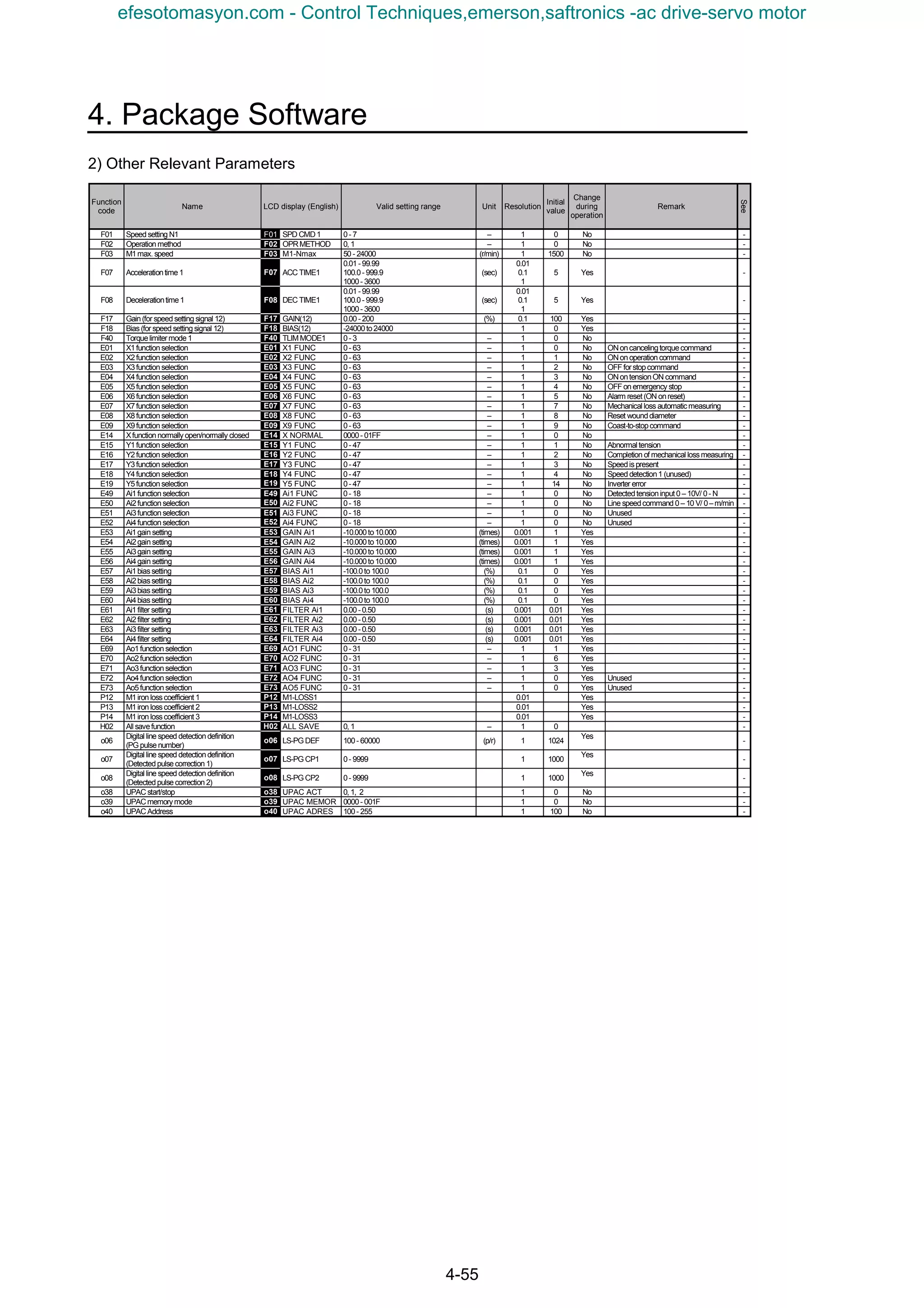
![4-56
4.3.6 Calculation Control Block Diagrams
1) Mechanical Loss Automatic Measuring Control Block
Mechanical loss
automatic measuring
Mechanical loss
torque data file
Speed command
Reads in torque
command
UPAC
Mechanical loss automatic
measuring command
X7
Y2
Automatic measuring
completion
(ON for two seconds on
completion)
- Use a hardware sequence to build a circuit which uses the completion command to turn off the
mechanical loss automatic measuring command .
- When you want to stop the automatic measuring on the way, turn off the mechanical loss automatic measuring
command .
Y2
X7
X7
2) Wound Diameter Calculation Control Block
Wound diameter
calculation
Output from
wound
diameter
calculation
*1
UPAC
Line speed command
Ai2
X8
Hardware
sequence or
T-Link
Line speed
(maximum)
Material thickness*
Minimum rotation
speed
Maximum diameter
Minimum coil
diameter
Initial diameter
POD
KEYPAD
panel
T-Link*
U03
U27
U31
U28
U12
U07
Reset to initial
diameter
Wound diameter reset
(ON on reset)
DC0-10V
100 to 2000/100 to 2000[mm]
100 to 2000/100 to 2000[mm]
100 to 2000/100 to 2000[mm]
15 to 1500/15 to 1500[r/min]
0 to 20000/0 to 2000[m/min]
1 to 30000/0.00 to 30[mm]
Actual rotation speed of
winding machine motor
U14
0 to 10000/0 to 100.00
Machine
rotation speed
Motor rotation
speed
Speed
reduction
ratio
Items marked by * can be set from the PLC after you add the T-Link I/F card.
efesotomasyon.com - Control Techniques,emerson,saftronics -ac drive-servo motor](https://image.slidesharecdn.com/vg7upacmanual-140613044924-phpapp01/75/Vg7-upac-manual-200-2048.jpg)
![4. Package Software
4-57
3) Tension Set Value Block
※2
Tension set
value calculation
Torque output
corresponding
to tension
UPAC
*4 ATR output
Maximum tension
setting range
Tension lower limit
(Alarm level)*
Tension upper limit
(Alarm level)*
Operation tension
setting*
Stall tension setting*
POD
KEYPAD
panel
T-Link*
U15
U14
U06
U05
U02
U01
0 to 980/0 to 980[N]
0 to 980/0 to 980[N]
0 to 1960/0 to 1960[N]
0 to 980/0 to 980[N]
0 to 10000/0 to 100.00
0 to 14700/0 to 1470[N]
*1 Output from wound
diameter calculation
*2 Output from taper
calculation
X2
X4
ON on tension ON
On during line operation
Machine
rotation speed
Motor rotation
speed
Speed
reduction
ratio
Items marked by * can be set from the PLC after you add the T-Link I/F card.
4) Taper Calculation Block
※2
Taper calculation
Output from
taper
calculation
*2
UPAC
Two-point taper
diameter setting
Two-point taper
setting
Linear taper setting*
U11
U10
U09
0 to 150/0 to 150[%]
0 to 150/0 to 150[%]
0 to 2000/0 to 2000[mm]
Output from wound
diameter calculation
*1
D
U10
U11
T
U09
Items marked by * can be set from the PLC after you add the T-Link I/F card.
efesotomasyon.com - Control Techniques,emerson,saftronics -ac drive-servo motor](https://image.slidesharecdn.com/vg7upacmanual-140613044924-phpapp01/75/Vg7-upac-manual-201-2048.jpg)
![4-58
5) ATR (Tension Feedback) Control
※2
ATR control
ATR
output
*4
UPAC
ATR ON delay timer
ATR OFF speed
Lower limit value while
stalling
Upper limit value
while stalling
Lower limit
value
While line is
at constant
speed
U58
U56
U44
U30
U29
U26
-300 to 300/-300 to 300[%]
0-100/0-1[m]
0 to 5000/0 to 5[sec]
U61
U48
0 to 100/0 to 100[N]
0 to 5000/0 to 5[sec]
ATR dead zone width
Tension feedback filter
setting
ATR OFF delay timer
0 to 5000/0 to 5[sec]
-300 to 300/-300 to 300[%]
-300 to 300/-300 to 300[%]
Upper limit
value
U25
-300 to 300/-300 to 300[%]
Lower limit
value
U24D time
U23I time
U22P gain
U21
-300 to 300/-300 to 300[%]
Upper limit
value
U20
-300 to 300/-300 to 300[%]
D time U19
0 to 10000/0 to 10.000[sec]
I time U18
0 to 10000/0 to 100.00[sec]
P gain U17
0 to 10000/0 to 10.000[times]
Maximum tension feedback
range setting
U13
0 to 14700/0 to 1470[N]
While line is
accelerating/
decelerating
Ai1Tension pickup value
DC0-10V
Set a value in [N] when Ai1
input is 10V
0 to 10000/0 to 10.000[times]
0 to 10000/0 to 100.00[sec]
0 to 10000/0 to 10.000[sec]
efesotomasyon.com - Control Techniques,emerson,saftronics -ac drive-servo motor](https://image.slidesharecdn.com/vg7upacmanual-140613044924-phpapp01/75/Vg7-upac-manual-202-2048.jpg)
![4. Package Software
4-59
6) Acceleration/Deceleration Compensation Torque Calculation Block
※2
Calculation for
acceleration/deceleration
compensation
Acceleration/
deceleration
compensation
torque
UPAC
Acceleration/deceleration
corresponding to material
Correction corresponding to torque
compensation
U42
U41
U36
U08
0 to 150/0 to 150[%]
0 to 32767/0 to 327.67[kg.m2
]
500 to 2000/500 to 2000[kg/m3]
U04
100 to 2000/100 to 2000[mm]
Torque setting corresponding to dynamic
mechanical loss (while operating)
U39
U38
U46
U45
0 to 3000/0 to 30[%]
U63
U62
Deceleration dv/dt on
emergency stop
U40
0 to -100/0 to -100[m/min/sec]
U34
0 to -1000
Acceleration detection level
(dead zone)
U33
0 to 1000
Ai2
Line speed
command
DC0-10V
0 to 3000/0 to 30[%]
0 to 5000/0 to 5[sec]
0 to 5000/0 to 5[sec]
Deceleration detection level
(dead zone)
dv/dt during acceleration
dv/dt during deceleration
Torque setting corresponding to dynamic
mechanical loss (while stalling)
Active time of dynamic mechanical loss
(while operating)
Material width setting*
Material mass setting*
Setting for GD2 corresponding to reel
Active time of dynamic mechanical loss
(while stalling)
Acceleration/deceleration
corresponding to reel
Correction corresponding to torque
compensation
0 to 150/0 to 150[%]
0 to 100/0 to 100[m/min/sec]
0 to -100/0 to -100[m/min/sec]
U14
0 to 10000/0 to 100.00
*1 Output from wound
diameter calculation
Machine
rotation speed
Motor rotation
speed
Speed
reduction
ratio
Items marked by * can be set from the PLC after you add the T-Link I/F card.
7) Mechanical Loss Compensation Torque Calculation Block
Calculation for
mechanical loss
compensation torque
Mechanical loss
compensation
torque
UPAC
*1 Output from wound
diameter calculation
Line speed command Ai2
DC0 to 10V
Mechanical loss
torque data file
N
U14
0 to 10000/0 to 100.00
Machine
rotation speed
Motor rotation
speed
Speed
reduction
ratio
τ
efesotomasyon.com - Control Techniques,emerson,saftronics -ac drive-servo motor](https://image.slidesharecdn.com/vg7upacmanual-140613044924-phpapp01/75/Vg7-upac-manual-203-2048.jpg)
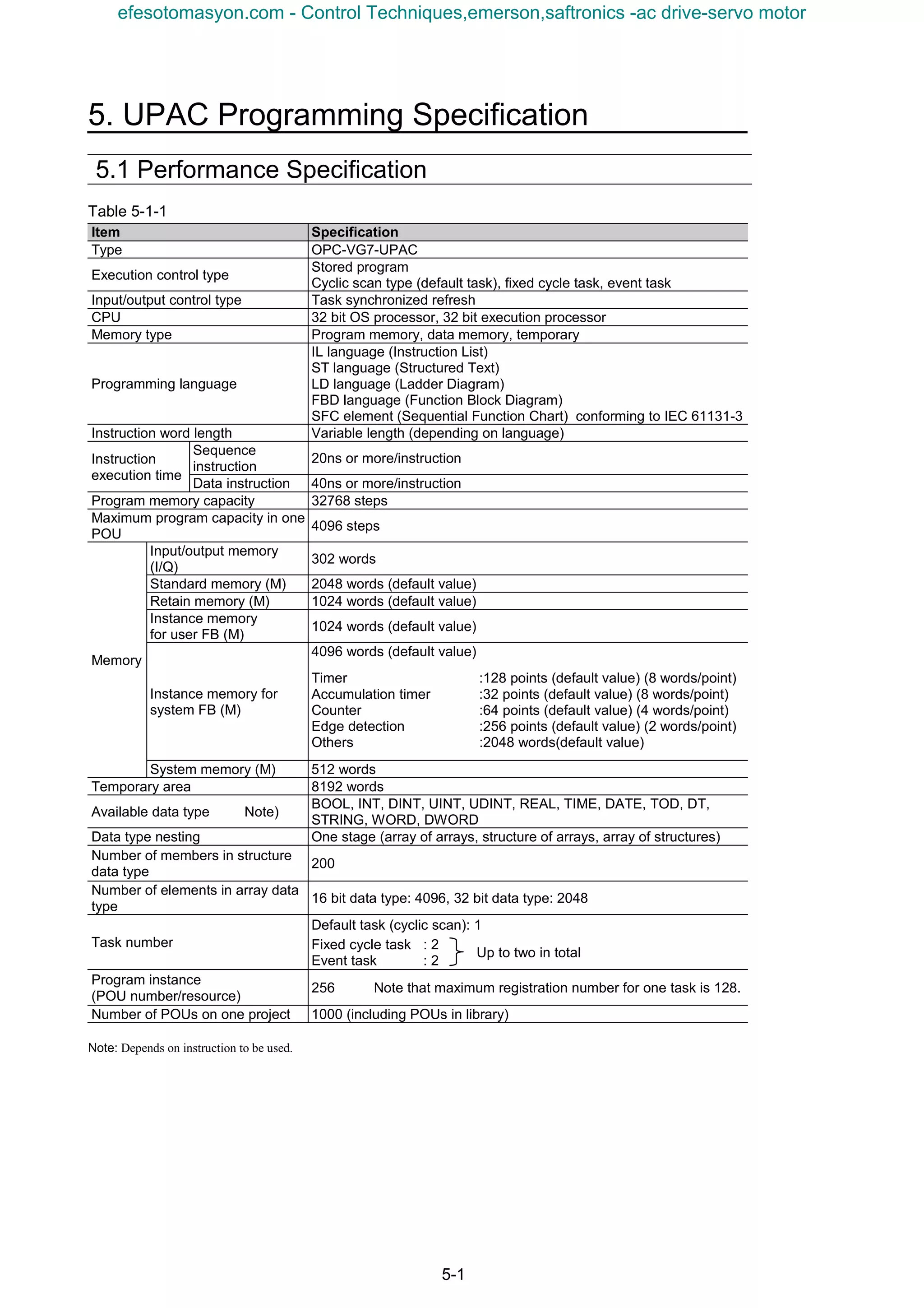
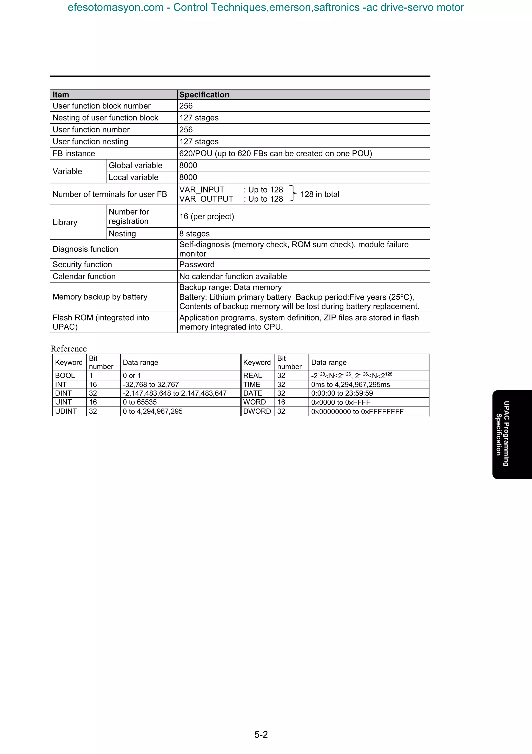
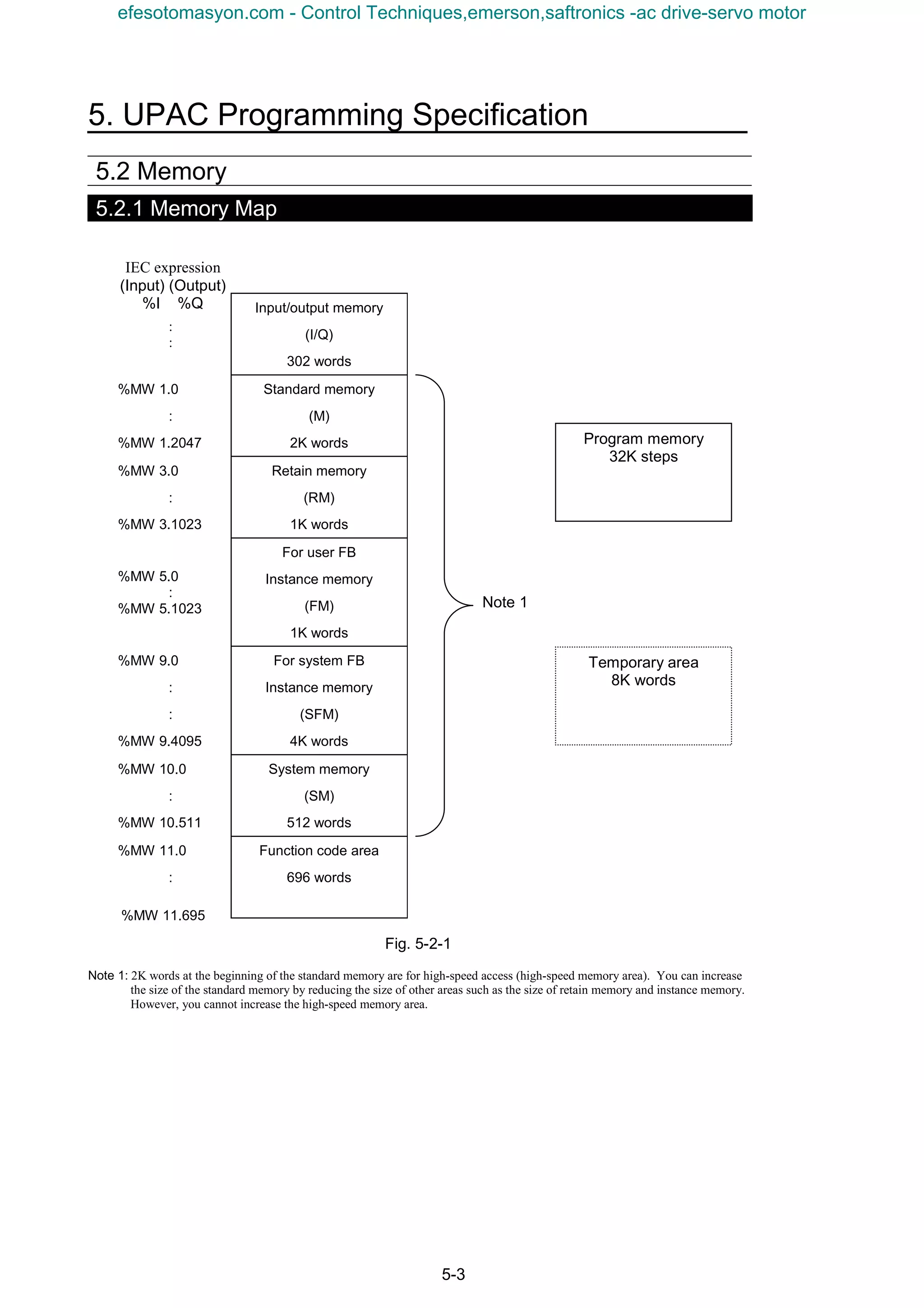
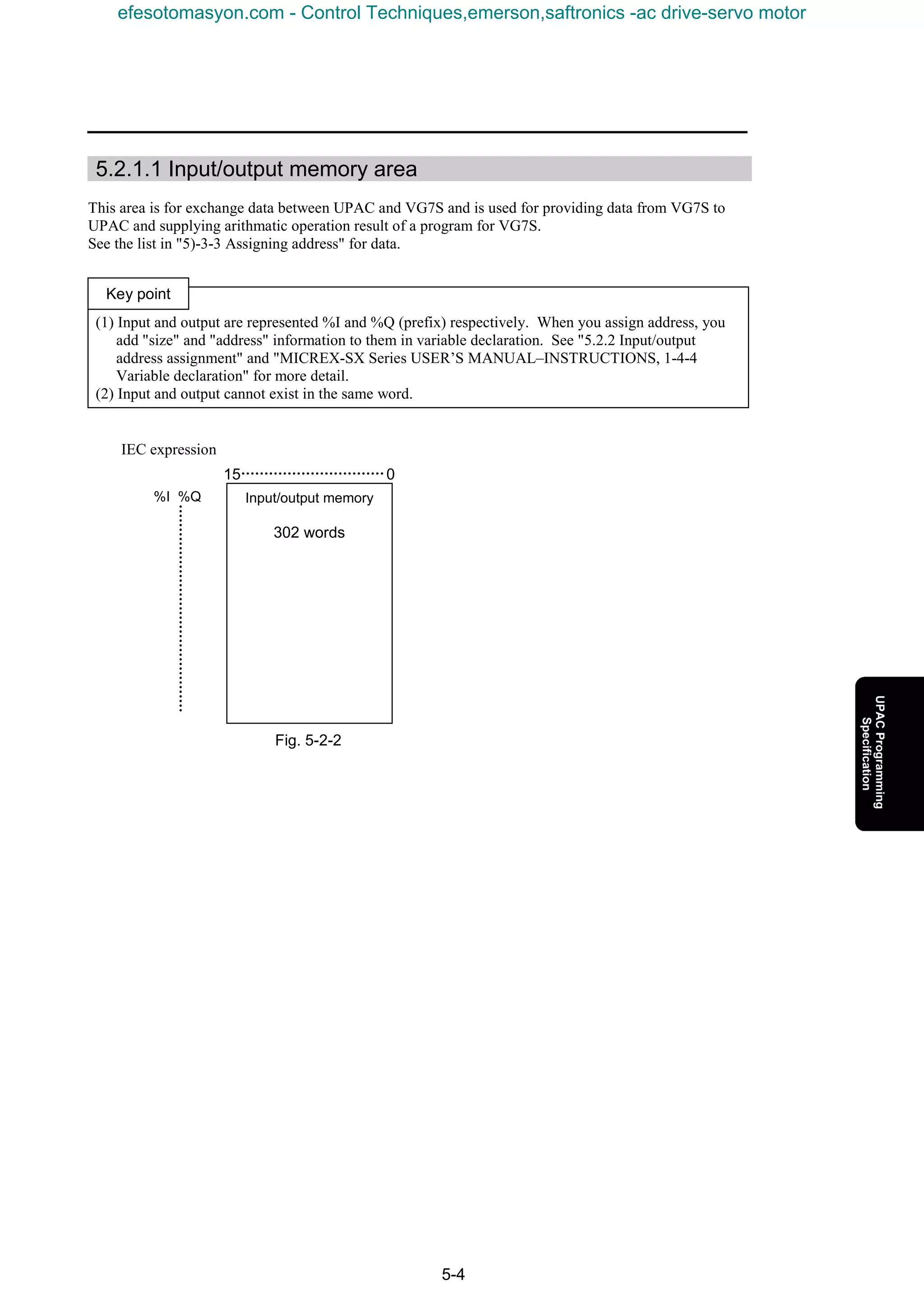
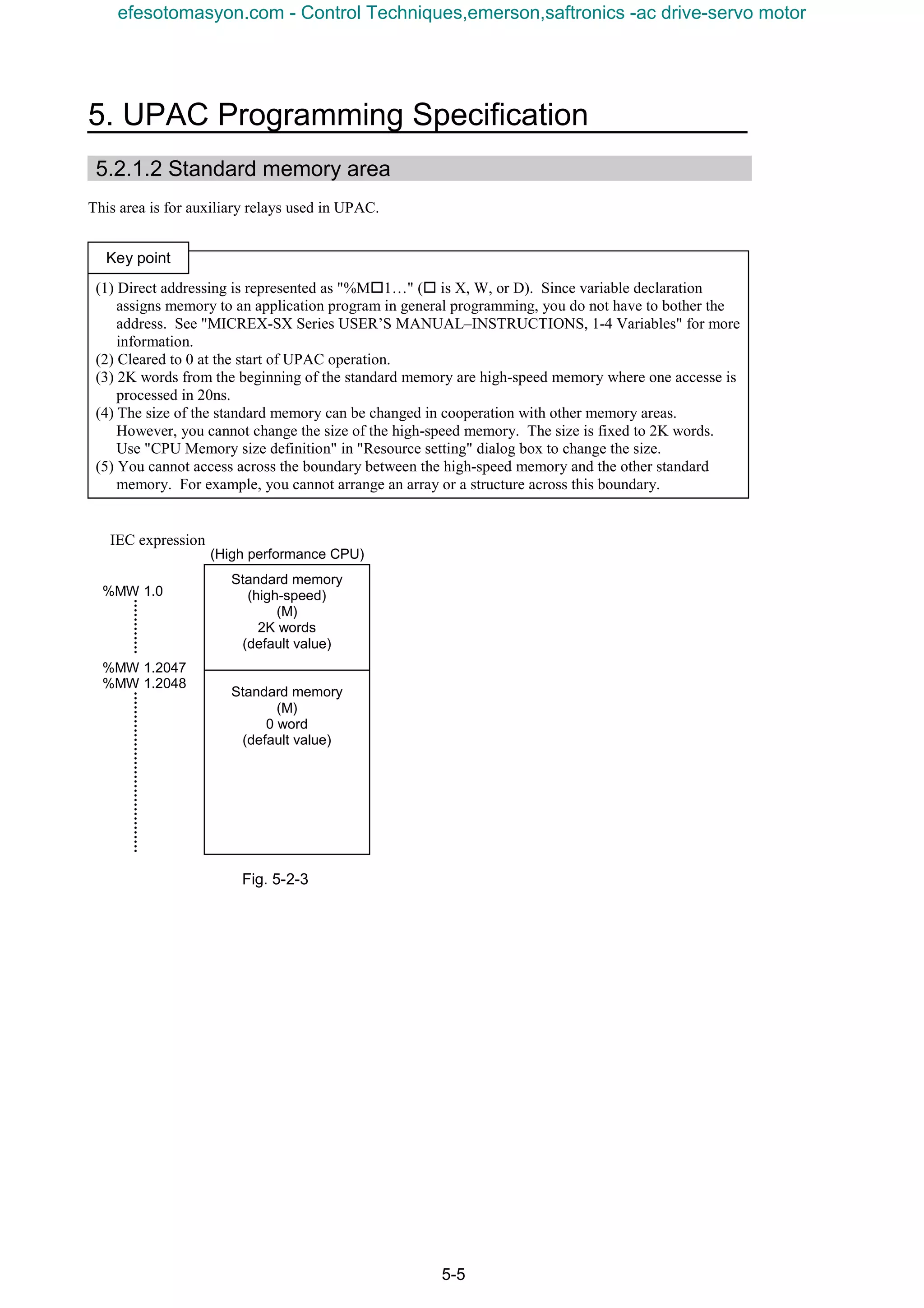
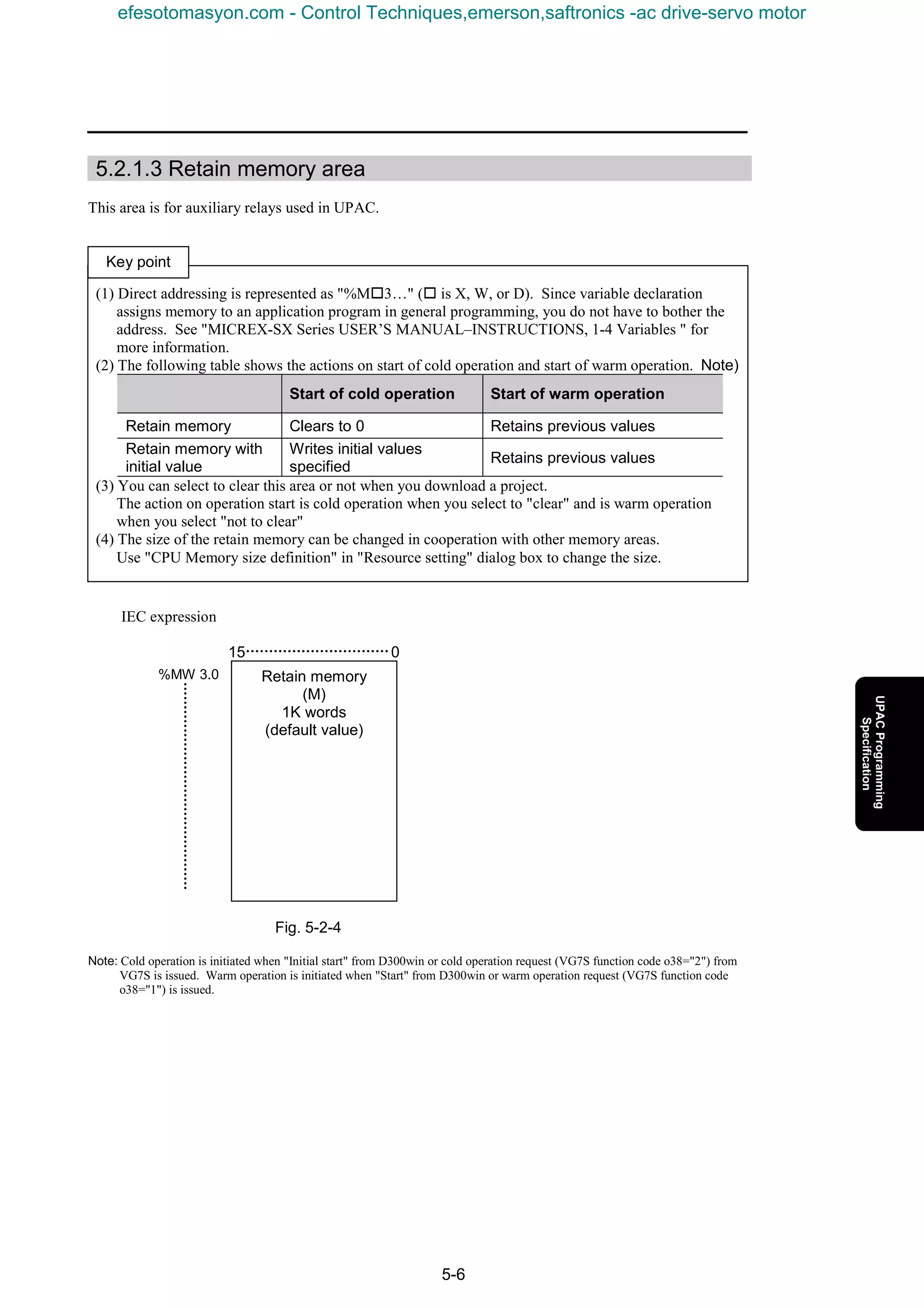
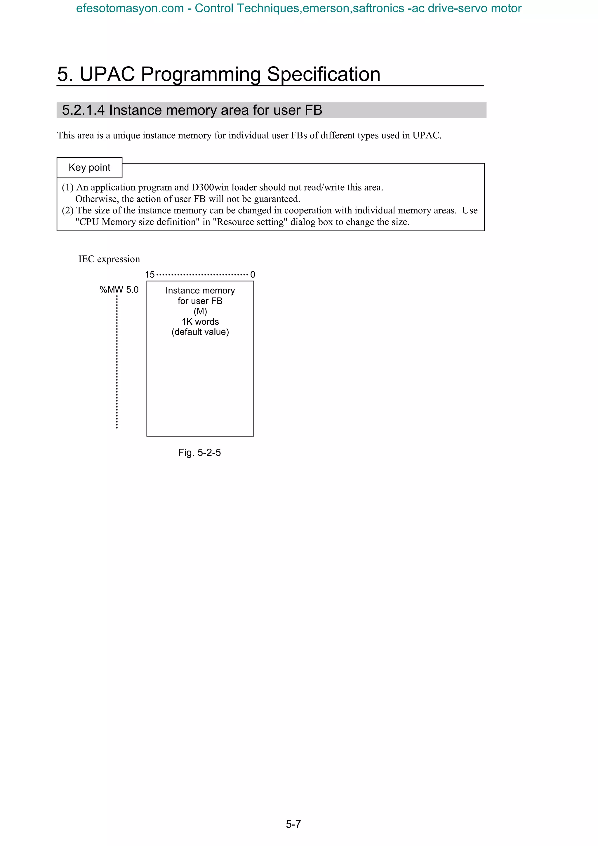
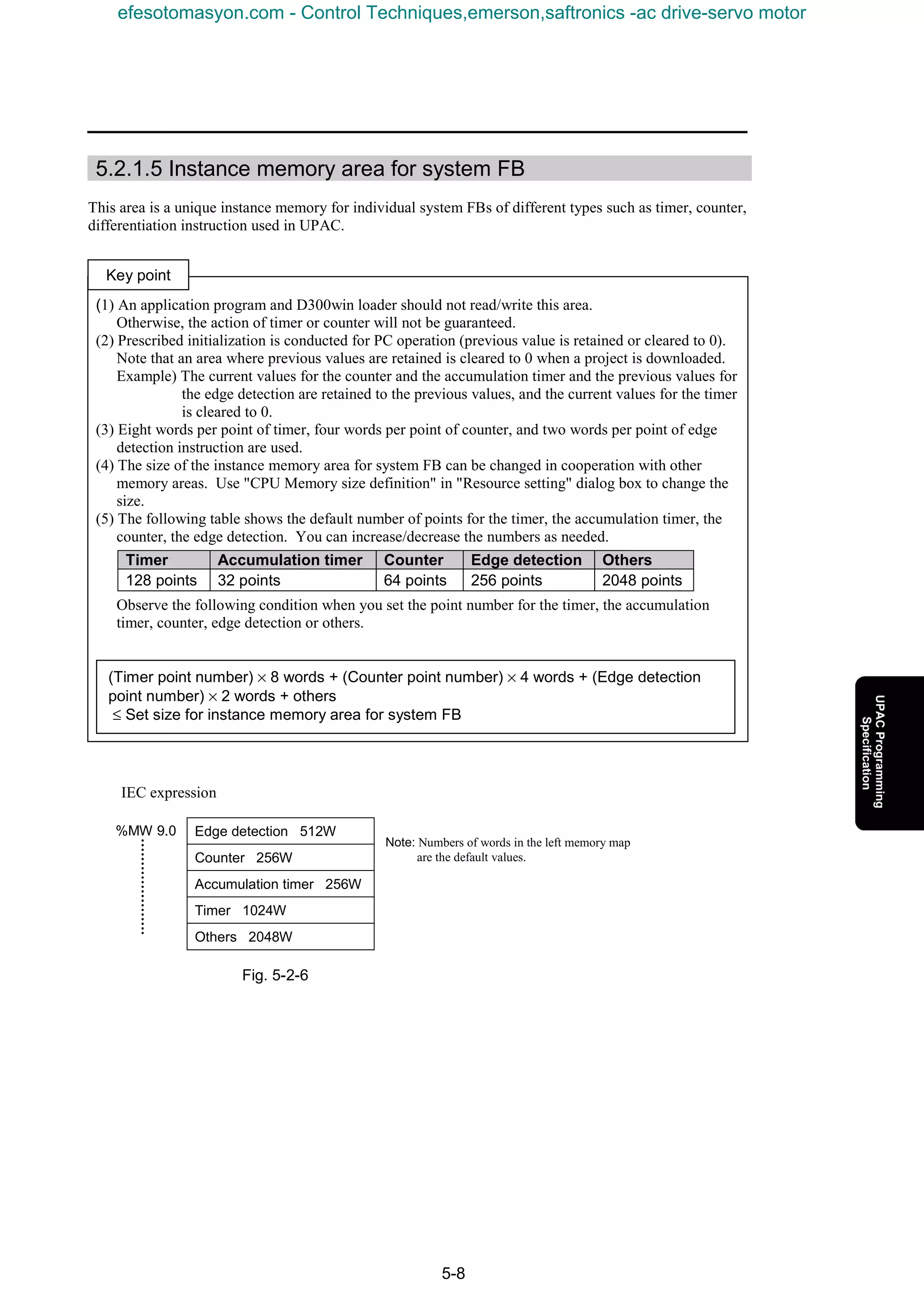
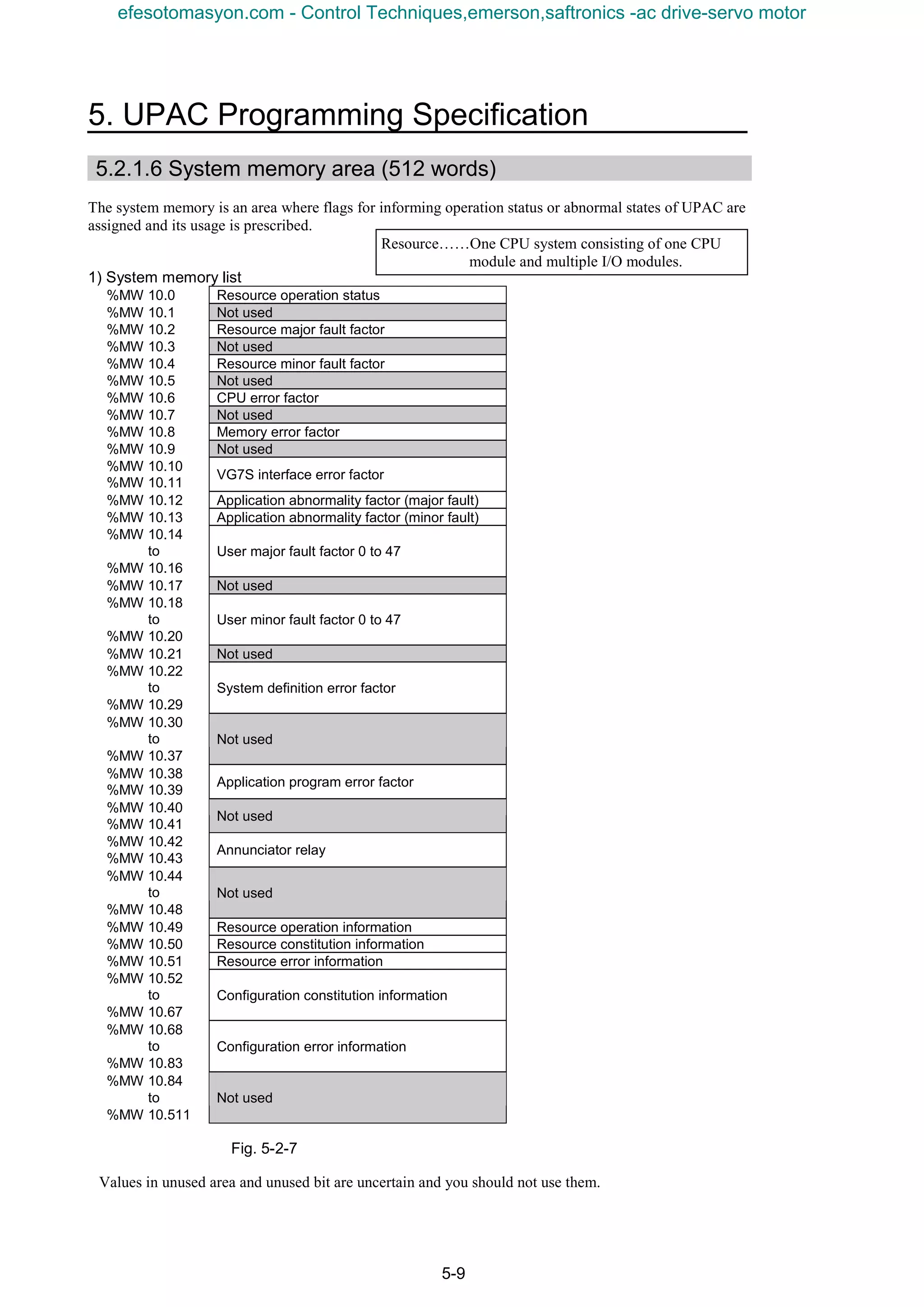
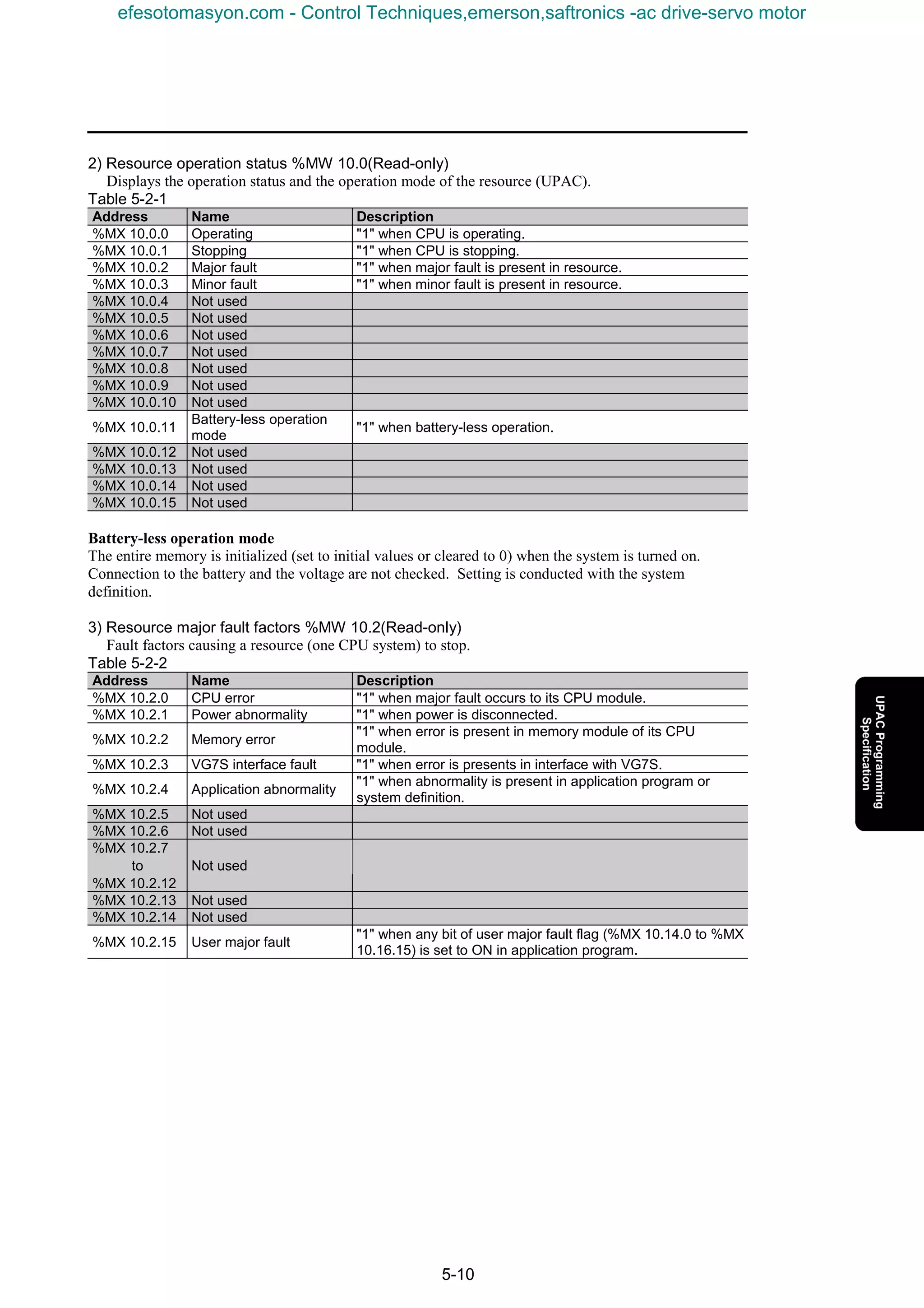
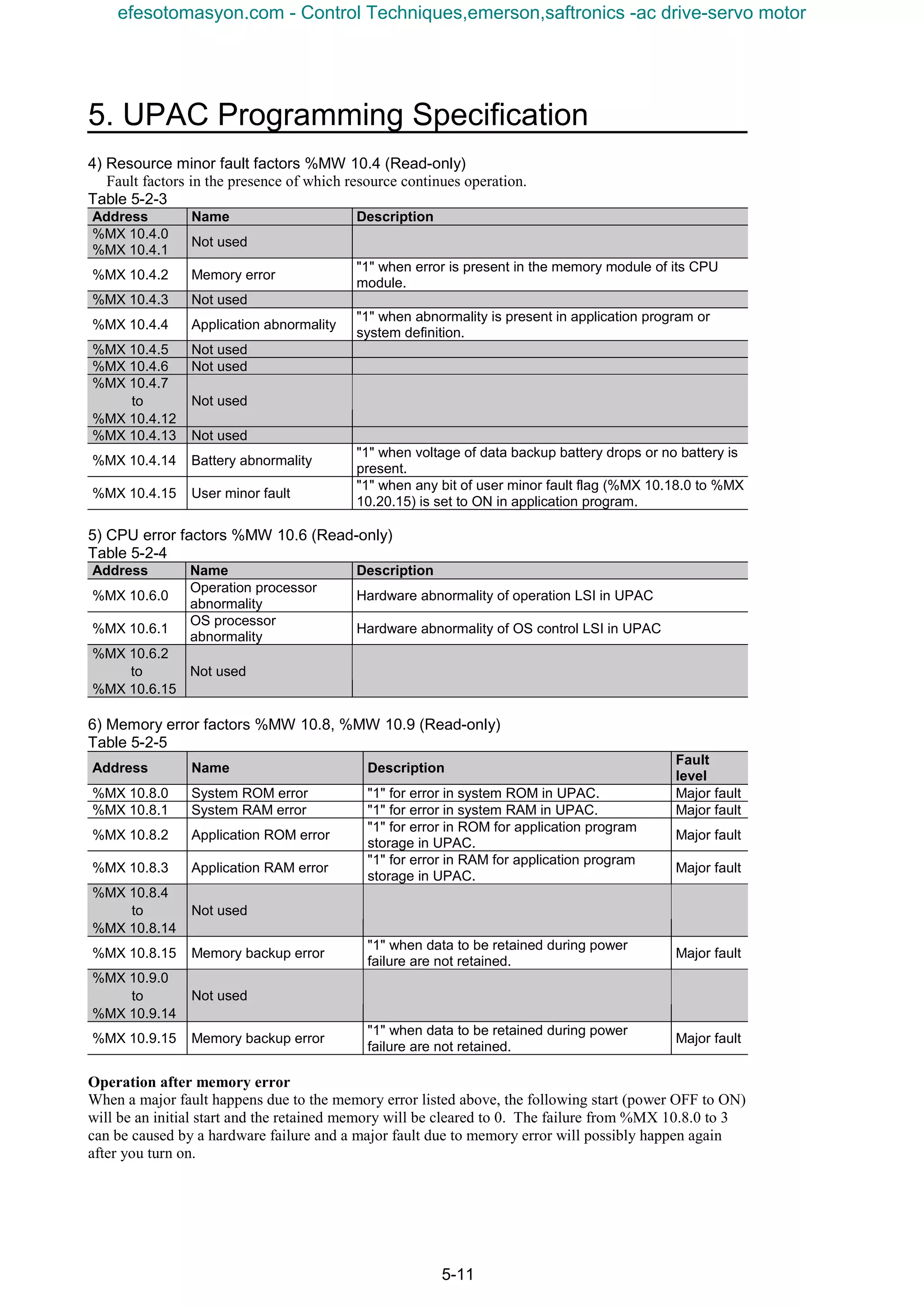
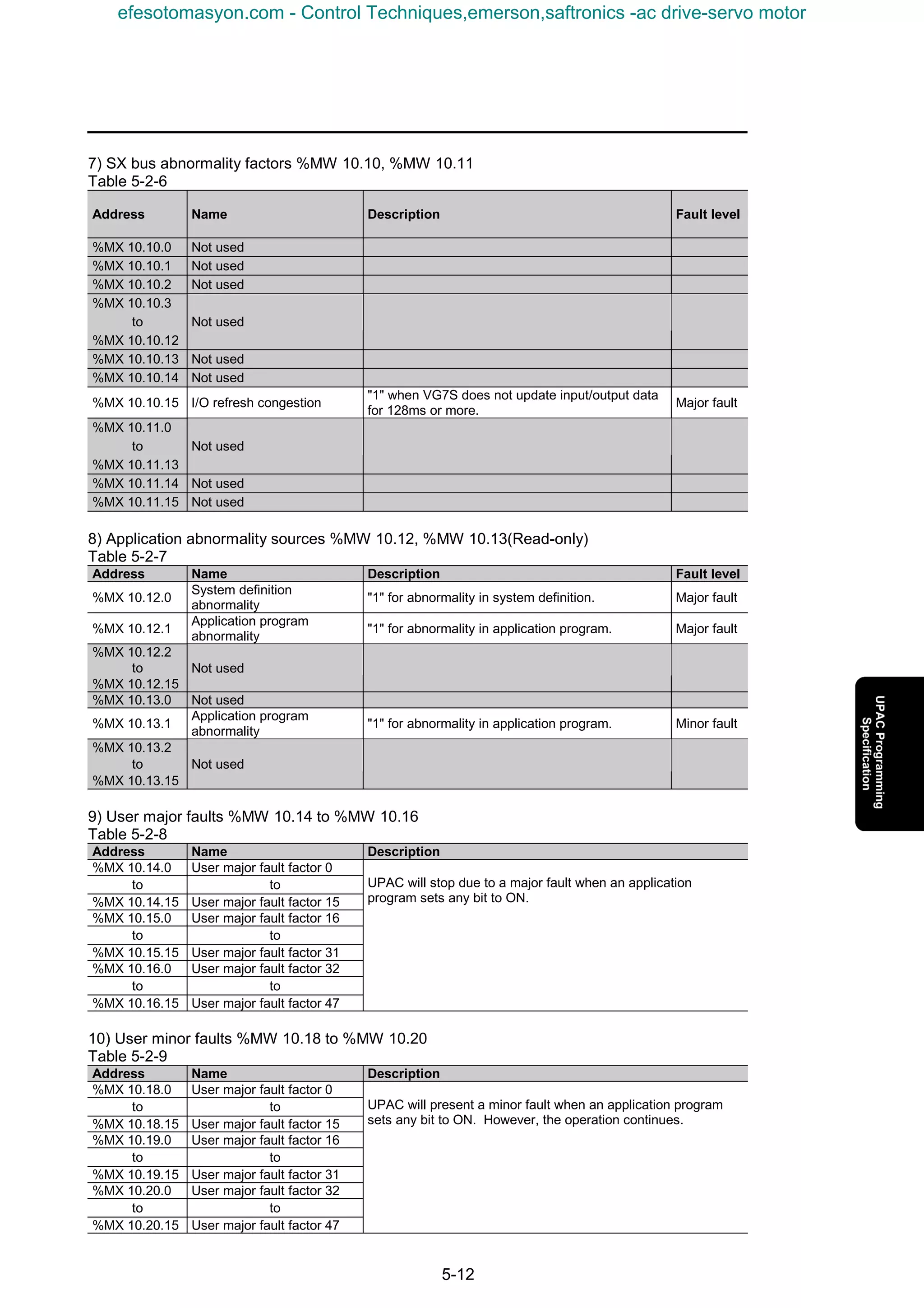
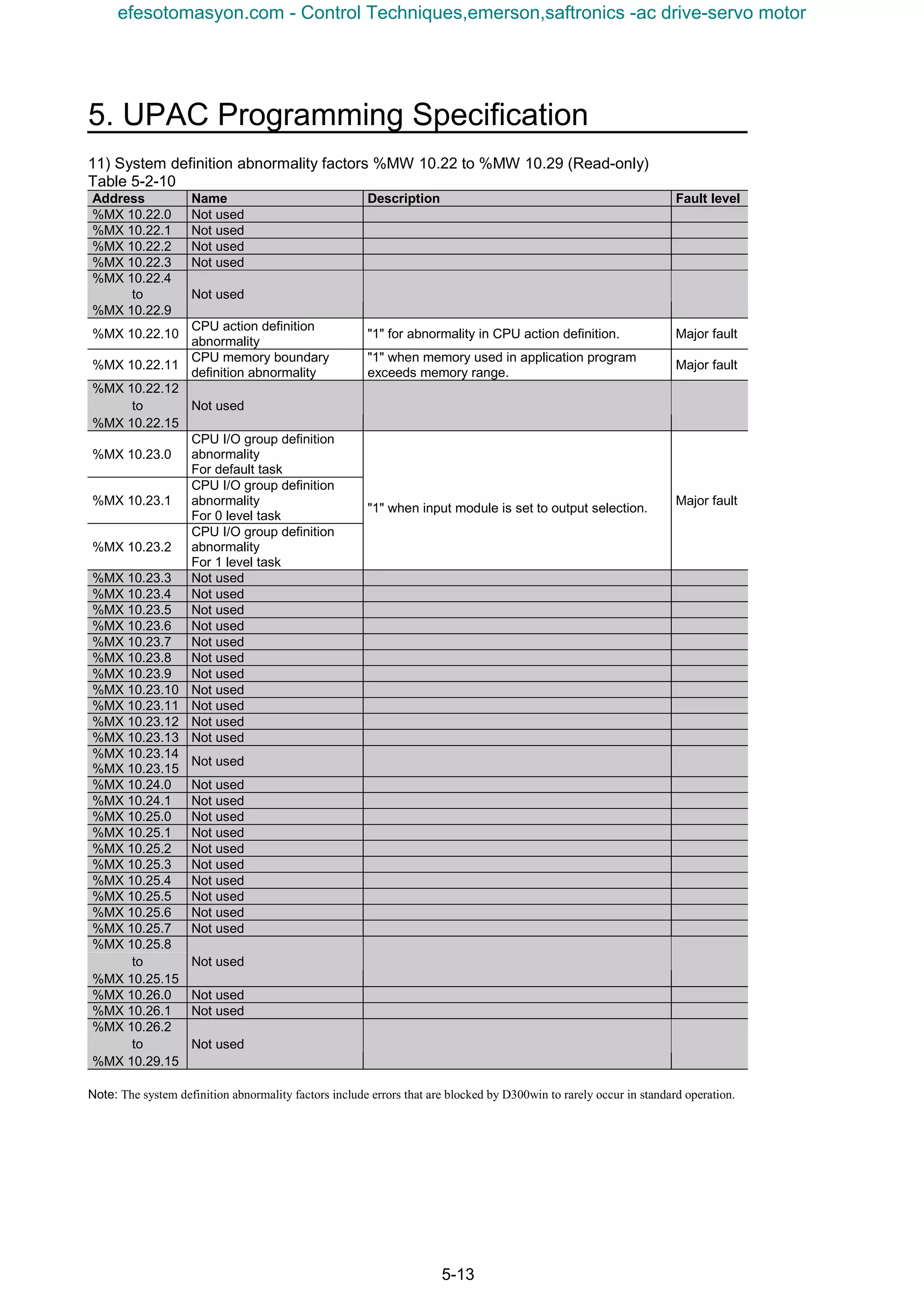
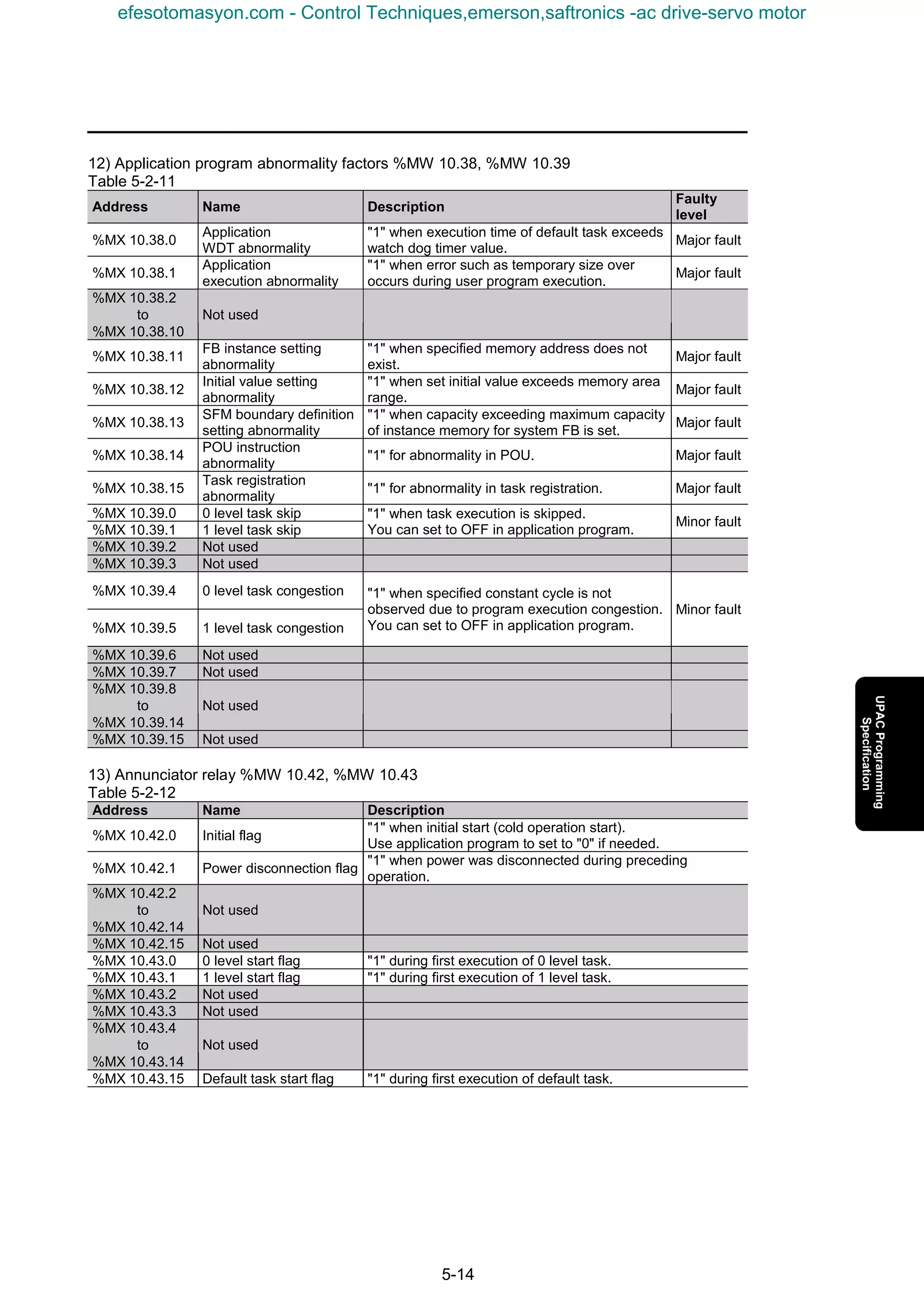
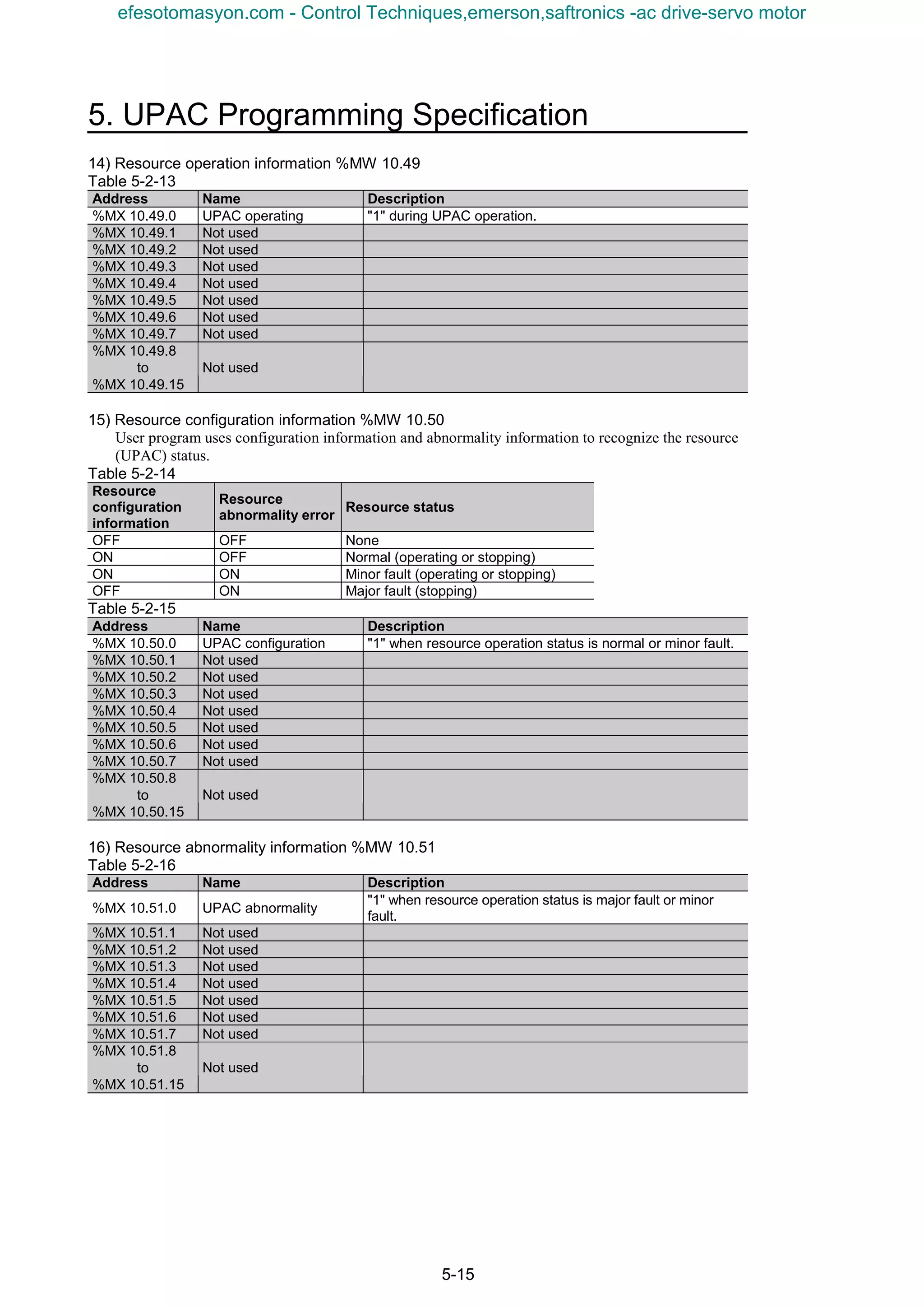
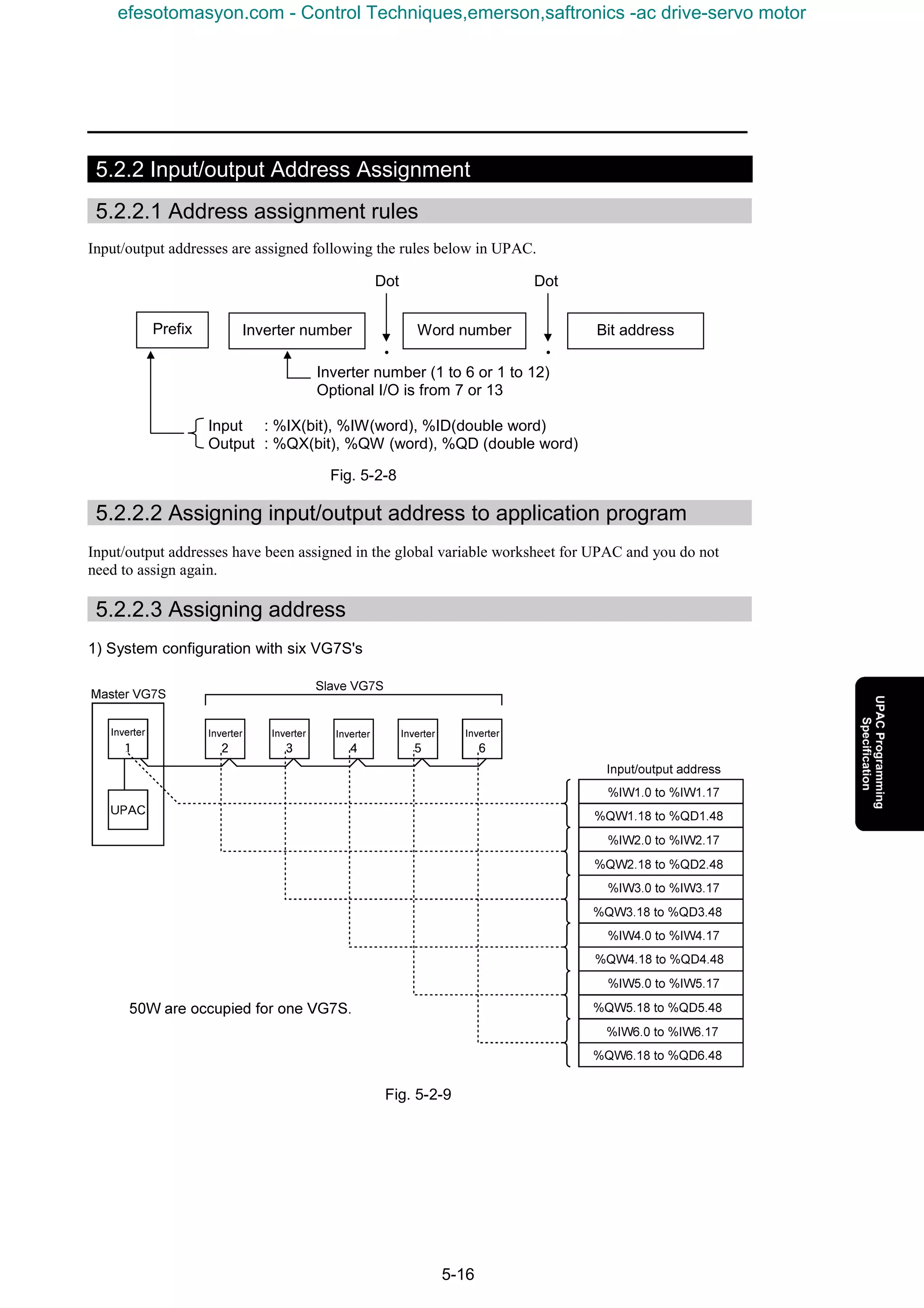
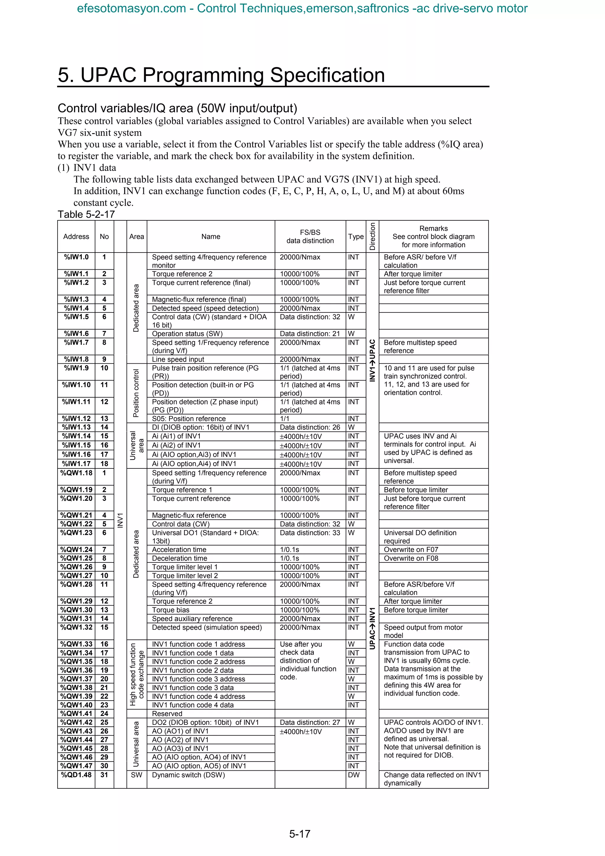
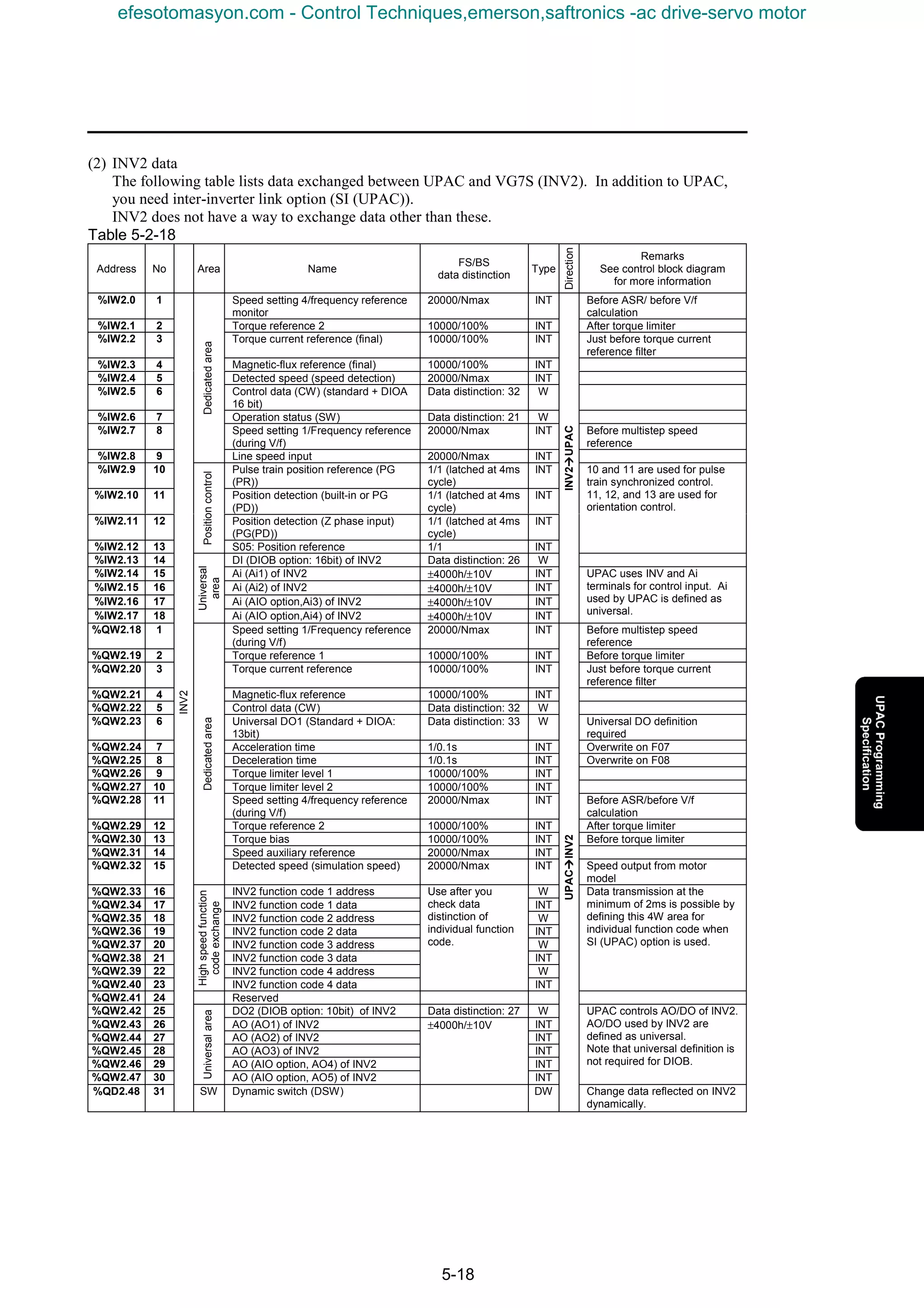
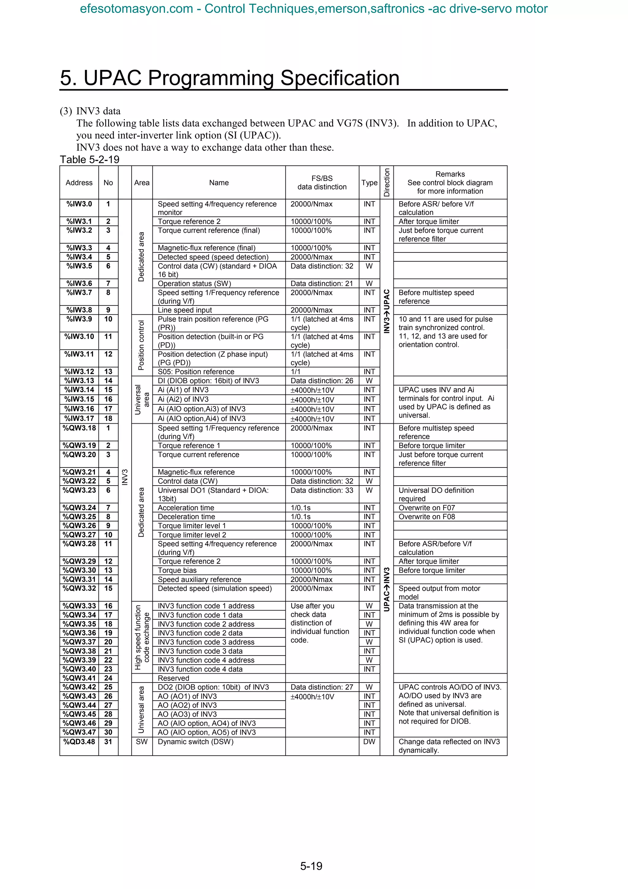
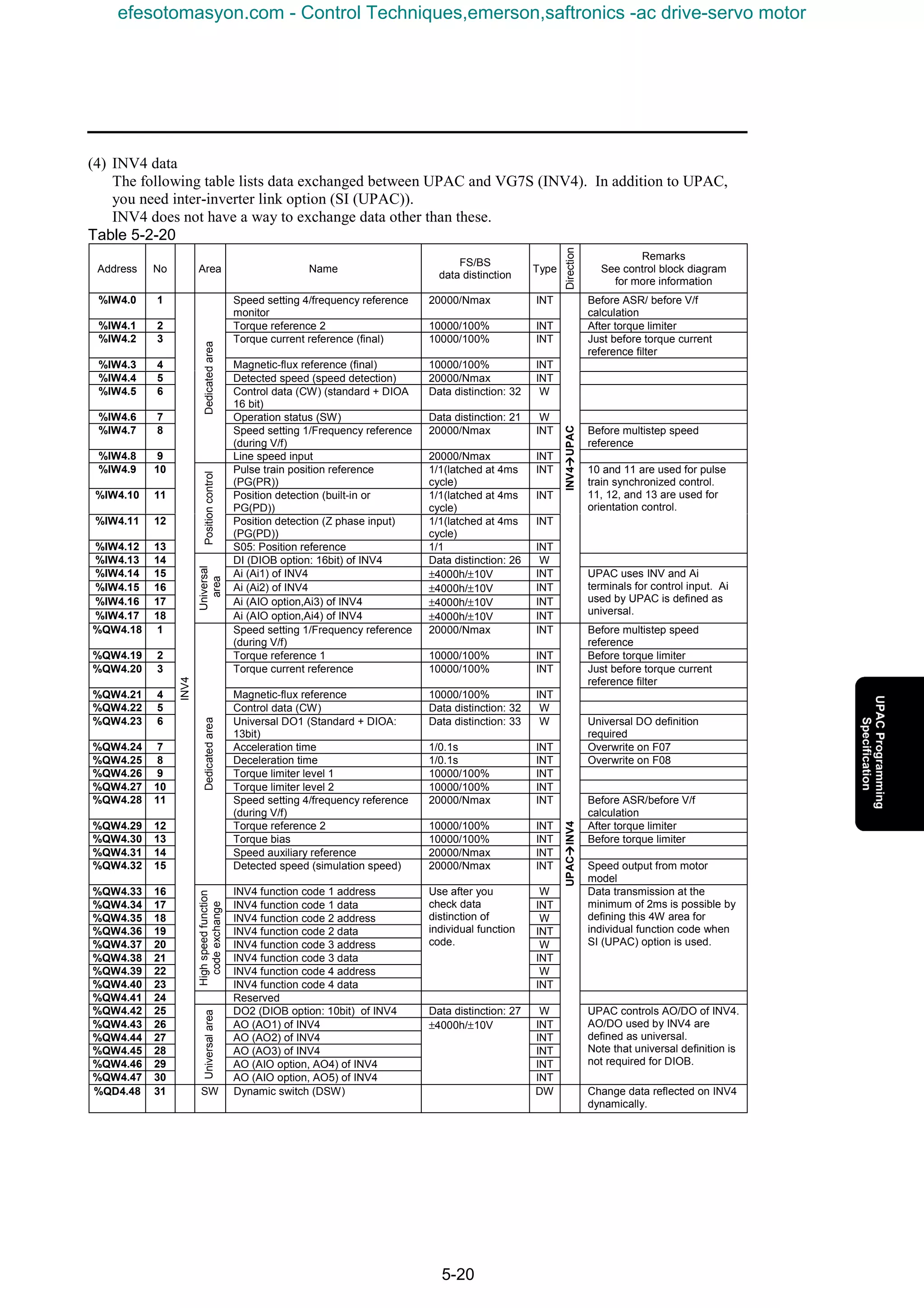
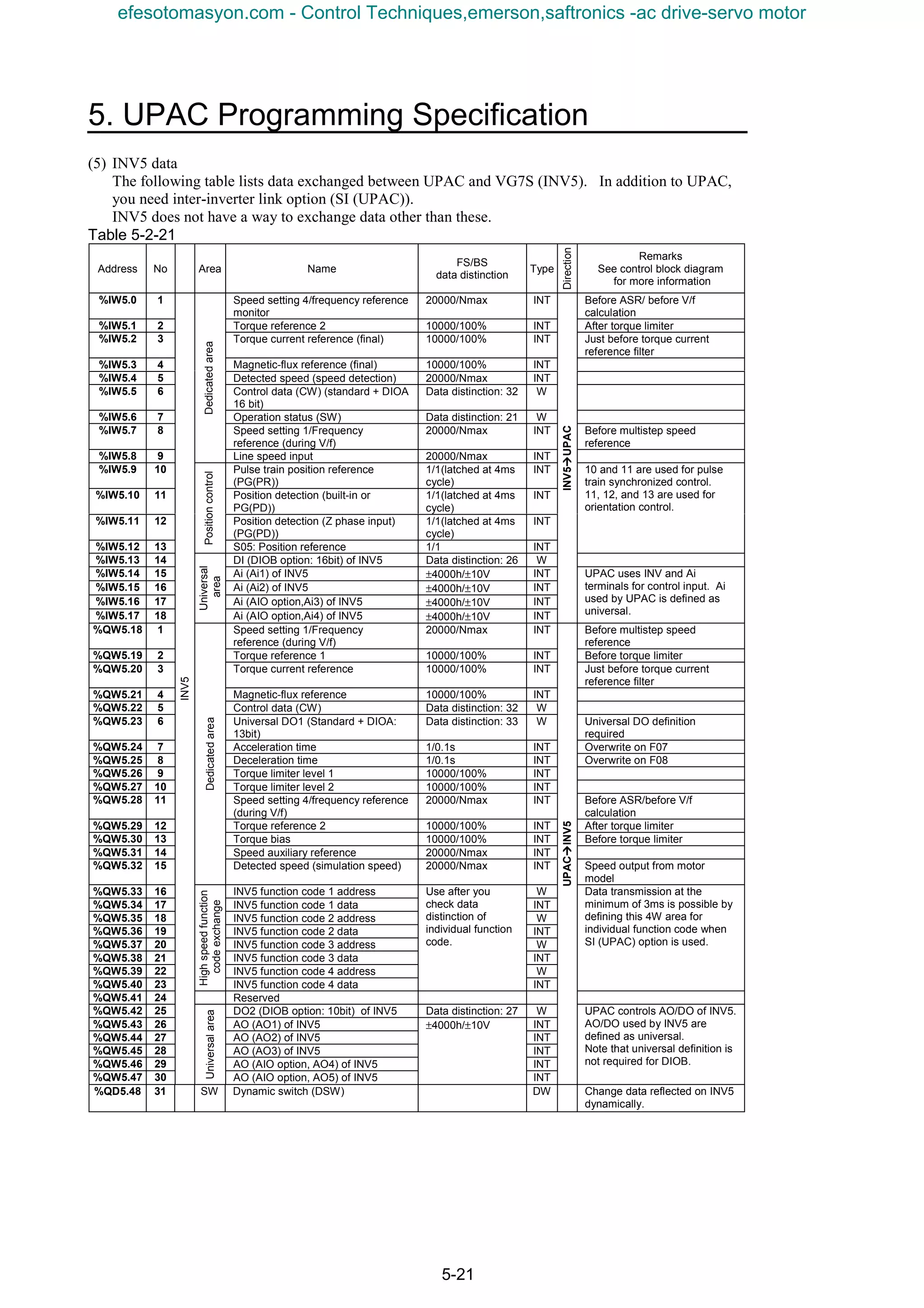

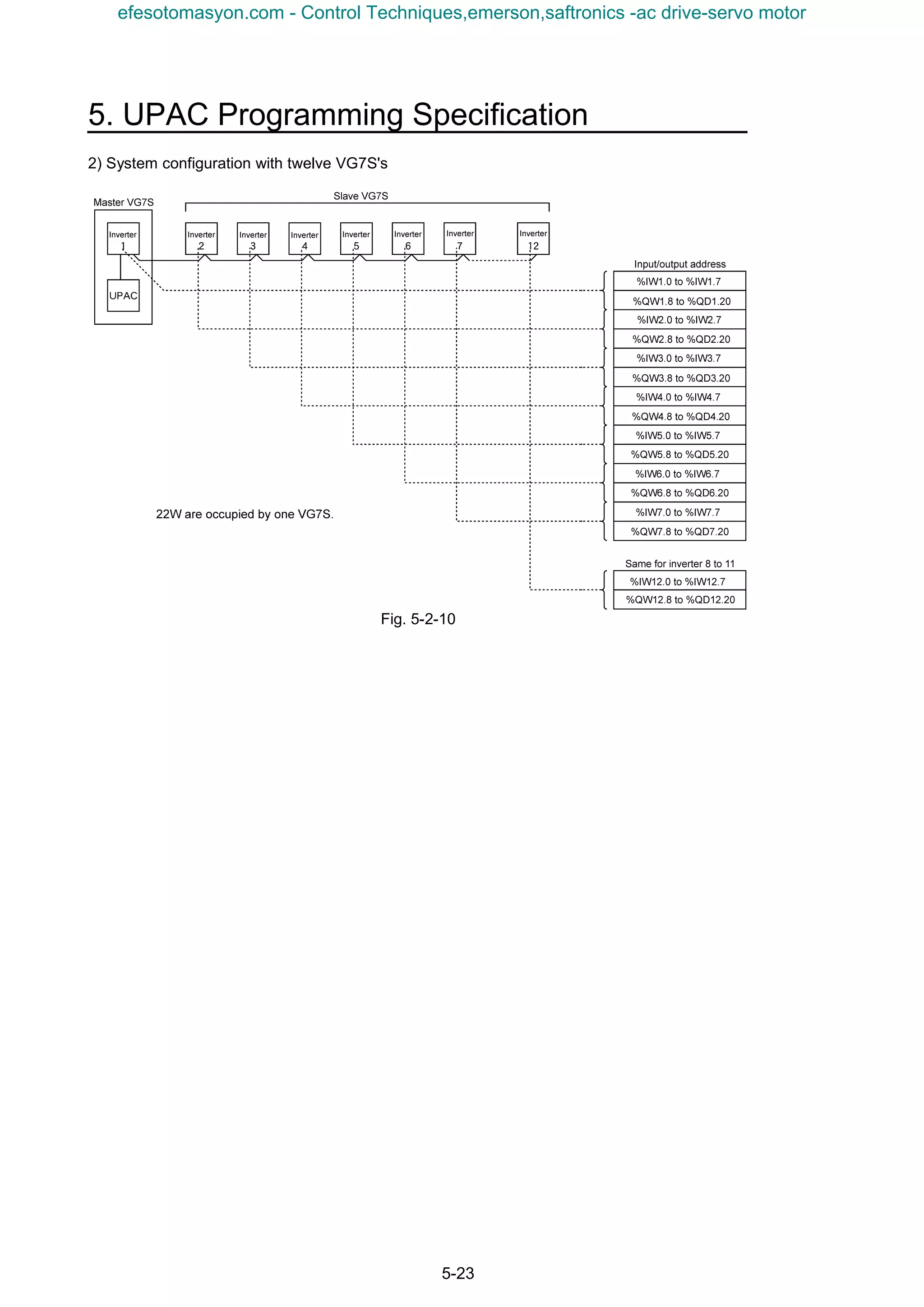
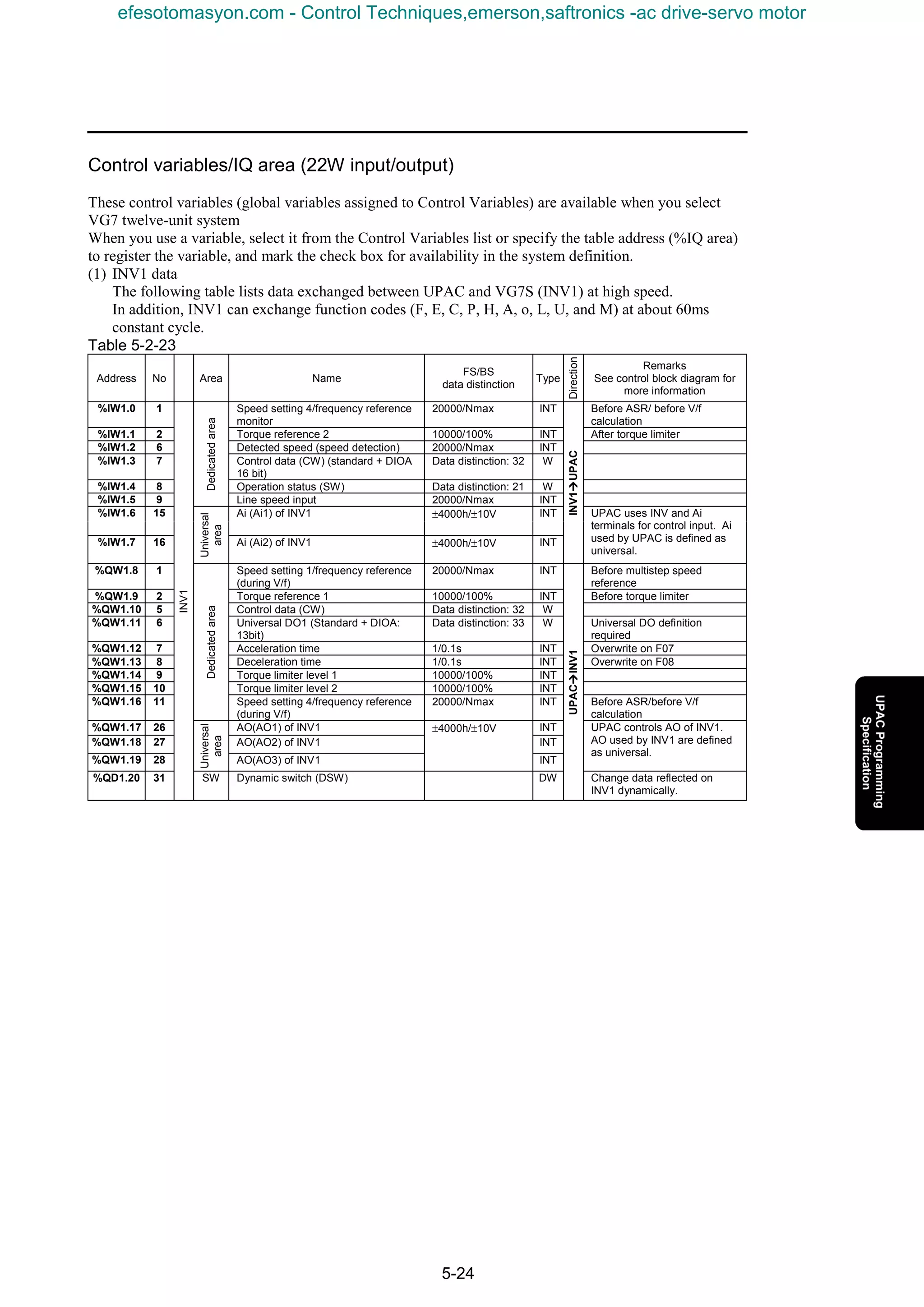
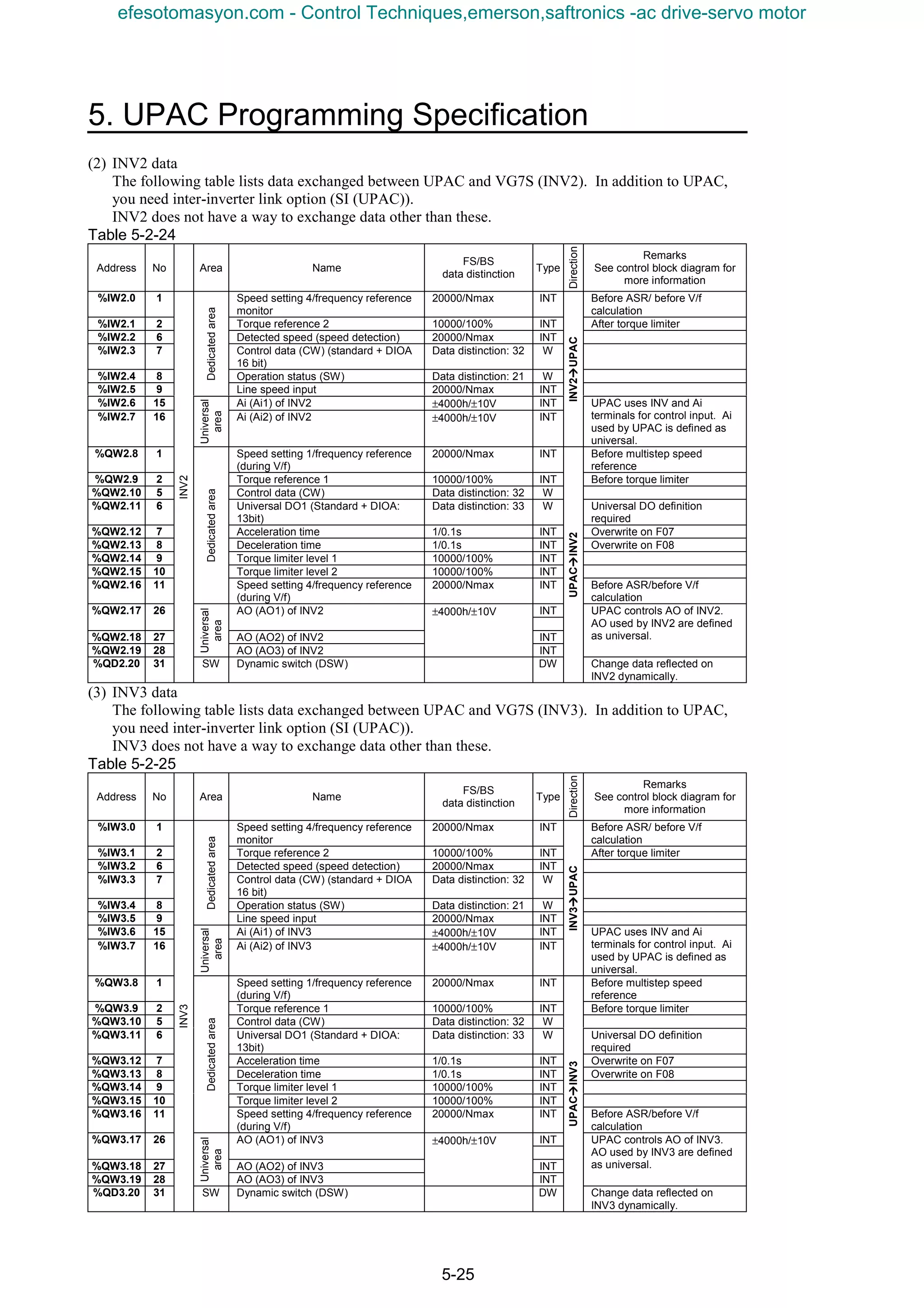
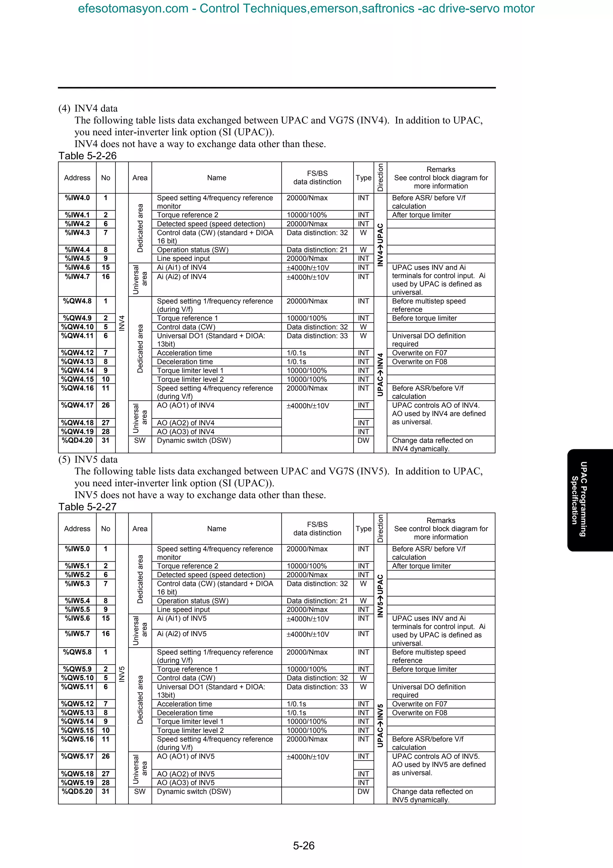
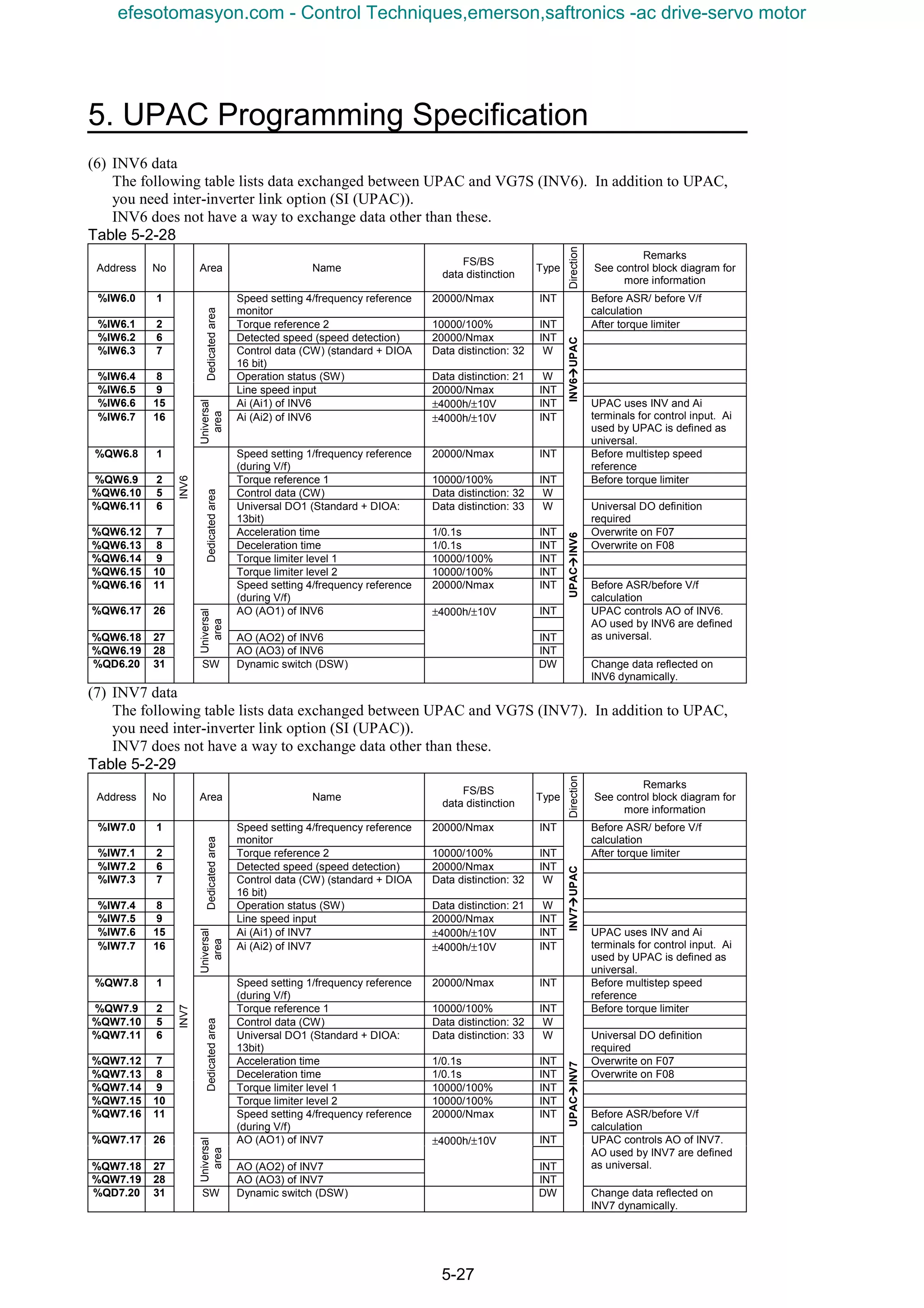


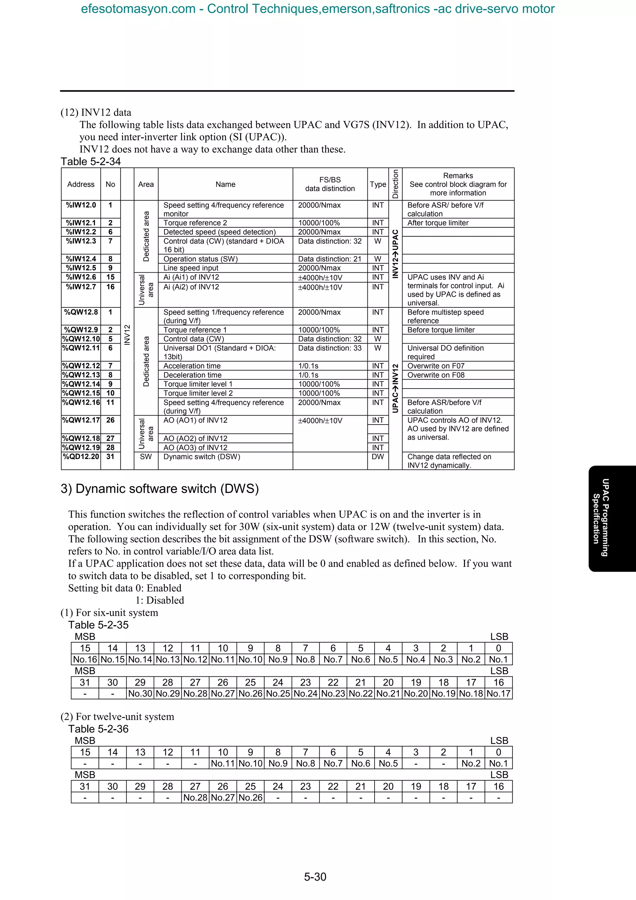
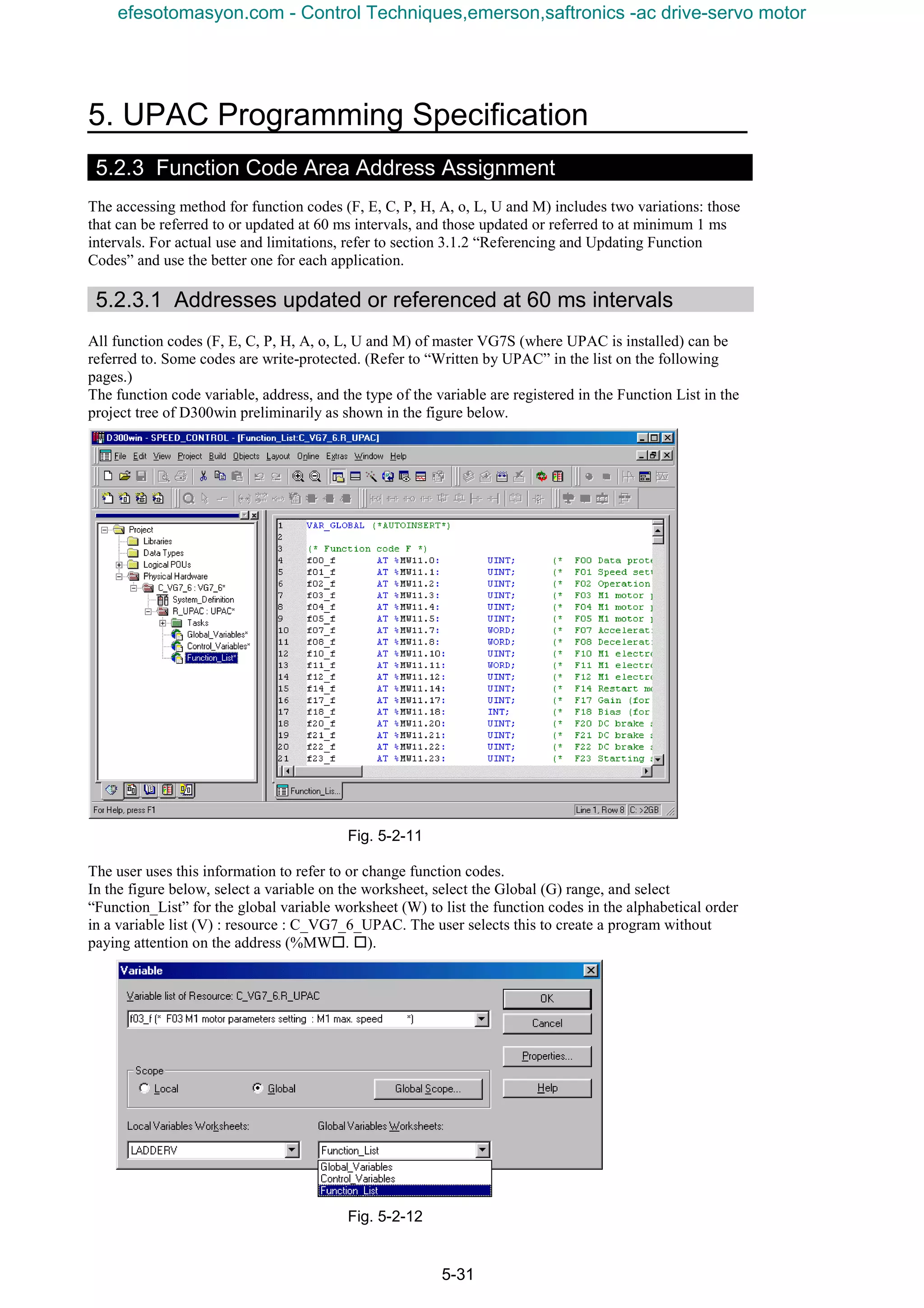
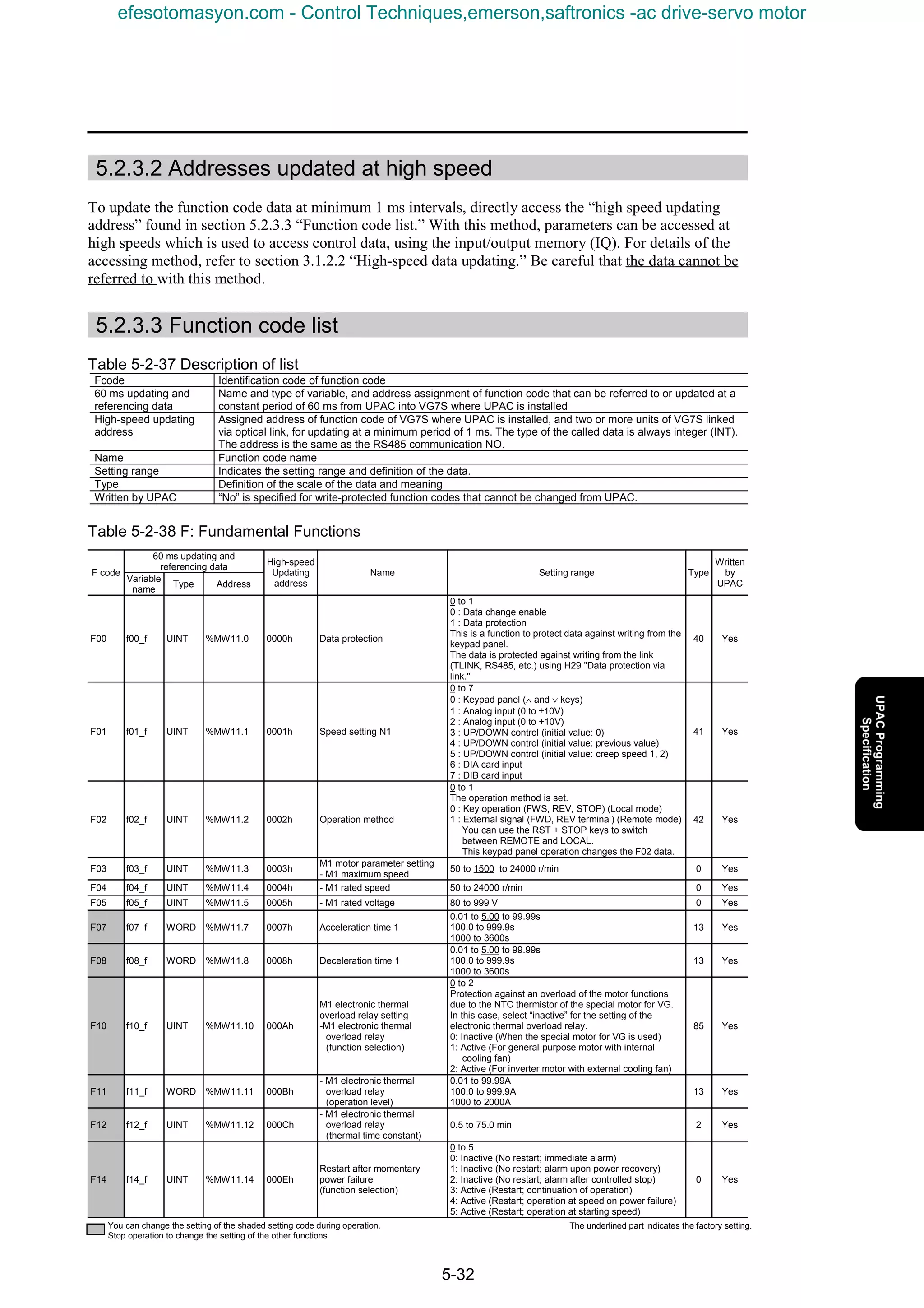
![5. UPAC Programming Specification
5-33
60 ms updating and
referencing data
F code
Variable
name
Type Address
High-speed
updating
address
Name Setting range Type
Written
by
UPAC
F17 f17_f UINT %MW11.17 0011h Gain (Speed setting signal 12) 0.0 to 100.0 to 200.0 % 2 Yes
F18 f18_f INT %MW11.18 0012h Bias (Speed setting signal 12) -24000 to 0 to 24000 r/min 5 Yes
F20 f20_f UINT %MW11.20 0014h
DC braking setting
- Starting speed
0 to 3600 r/min 0 Yes
F21 f21_f UINT %MW11.21 0015h - Operation level 0 to 100 % 16 Yes
F22 f22_f UINT %MW11.22 0016h - Braking time
0.0 to 30.0 s
0.0 : Inactive
0.1 to 30.0 s
2 Yes
F23 f23_f UINT %MW11.23 0017h Starting speed
0.0 to 150.0 r/min
The frequency is limited so as not to fall below 0.1 Hz
(sensorless or under V/f control).
2 Yes
F24 f24_f UINT %MW11.24 0018h Starting speed (holding time) 0.00 to 10.00 s 3 Yes
F26 f26_f UINT %MW11.26 001Ah
Motor sound
(carrier frequency)
0.75 to 7 to 15 kHz 10 Yes
F27 f27_f UINT %MW11.27 001Bh Motor sound (tone)
0 to 3
0 : Level 0
1 : Level 1
2 : Level 2
3 : Level 3
0 Yes
F36 f36_f UINT %MW11.36 0024h 30RY operation mode
0 to 1
0 : Excitation upon alarm
1 : Excitation during regular operation
43 Yes
F37 f37_f UINT %MW11.37 0025h
Stopping speed setting
- Stopping speed
0.0 to 10.0 to 150.0 r/min
The frequency is limited so as not to fall below 0.1 Hz
(sensorless or under V/f control).
2 Yes
F38 f38_f UINT %MW11.38 0026h
- Stopping speed
(detection method)
0 to 1
0 : Detected speed
1 : Commanded speed
However, the setting is fixed at 1 under V/f control.
90 Yes
F39 f39_f UINT %MW11.39 0027h
- Stopping speed
(zero speed holding time)
0.00 to 0.50 to 10.00 s 3 Yes
F40 f40_f UINT %MW11.40 0028h
Toque limit setting
- Torque limit mode 1
0 to 3
0 : Torque limit invalid
1 : Torque limit
2 : Power limit
3 : Torque and current limit
44 Yes
F41 f41_f UINT %MW11.41 0029h - Torque limit mode 2
0 to 3
0 : Same limiting level (level 1) for 4 quadrants
1 : Drive torque (level 1) braking (level 2)
2 : Upper limit (level 1), lower limit (level 2)
3 : Same limiting level for four quadrants with
changeover between level 1 and level 2
Level 1 and Level 2 indicate the data of destination of
settings 42 and 43.
45 Yes
F42 f42_f UINT %MW11.42 002Ah
- Torque limit (level 1)
selection
0 to 5
0 : Function code (F44)
1 : Ai[TL-REF1]
2 : DIA card
3 : DIB card
4 : Link valid
5 : PID output
46 Yes
F43 f43_f UINT %MW11.43 002Bh
- Torque limit (level 2)
selection
0 to 5
0 : Function code (F45)
1 : Ai[TL-REF2]
2 : DIA card
3 : DIB card
4 : Link valid
5 : PID output
47 Yes
F44 f44_f INT %MW11.44 002Ch - Torque limit (level 1) -300 to 150 to 300 % 5 Yes
F45 f45_f INT %MW11.45 002Dh - Torque limit (level 2) -300 to 10 to 300 % 5 Yes
F46 f46_f INT %MW11.46 002Eh
- Mechanical loss
compensation
-300.00 to 0.00 to 300.00 %
Used to compensate for mechanical loss of the load.
7 Yes
F47 f47_f INT %MW11.47 002Fh - Torque bias T1
-300.00 to 0.00 to 300.00 %
This setting can be added to the torque reference.
Use DI to switch among torque bias T1, T2 and T3.
7 Yes
F48 f48_f INT %MW11.48 0030h - Torque bias T2
-300.00 to 0.00 to 300.00 %
This setting can be added to the torque reference.
Use DI to switch among torque bias T1, T2 and T3.
7 Yes
F49 f49_f INT %MW11.49 0031h - Torque bias T3
-300.00 to 0.00 to 300.00 %
This setting can be added to the torque reference.
Use DI to switch among torque bias T1, T2 and T3.
7 Yes
F50 f50_f UINT %MW11.50 0032h - Torque bias starting timer
0.00 to 1.00 s
( 300% / 1.00s )
Set the time to reach 300%.
3 Yes
F51 f51_f UINT %MW11.51 0033h
- Torque command monitor
(polarity selection)
0 to 1
Polarity selection of data output related to torque (AO,
keypad panel, code M)
0 : Torque polarity
1 : A positive value for driving, and a negative value for
braking.
48 Yes
F52 f52_f WORD %MW11.52 0034h
Keypad panel LED, LCD
monitor setting
- LED monitor (display
coefficient A)
-999.00 to 1.00 to 999.00
Set the conversion coefficient for determining the load
shaft speed and line speed displayed on the LED.
Displayed value = motor speed x (0.01 to 200.00)
The setting is effective only in the 0.01 to 200.00 range
and values out of the allowable range are restricted.
12 Yes
You can change the setting of the shaded setting code during operation.
Stop operation to change the setting of the other functions.
The underlined part indicates the factory setting.
efesotomasyon.com - Control Techniques,emerson,saftronics -ac drive-servo motor](https://image.slidesharecdn.com/vg7upacmanual-140613044924-phpapp01/75/Vg7-upac-manual-237-2048.jpg)
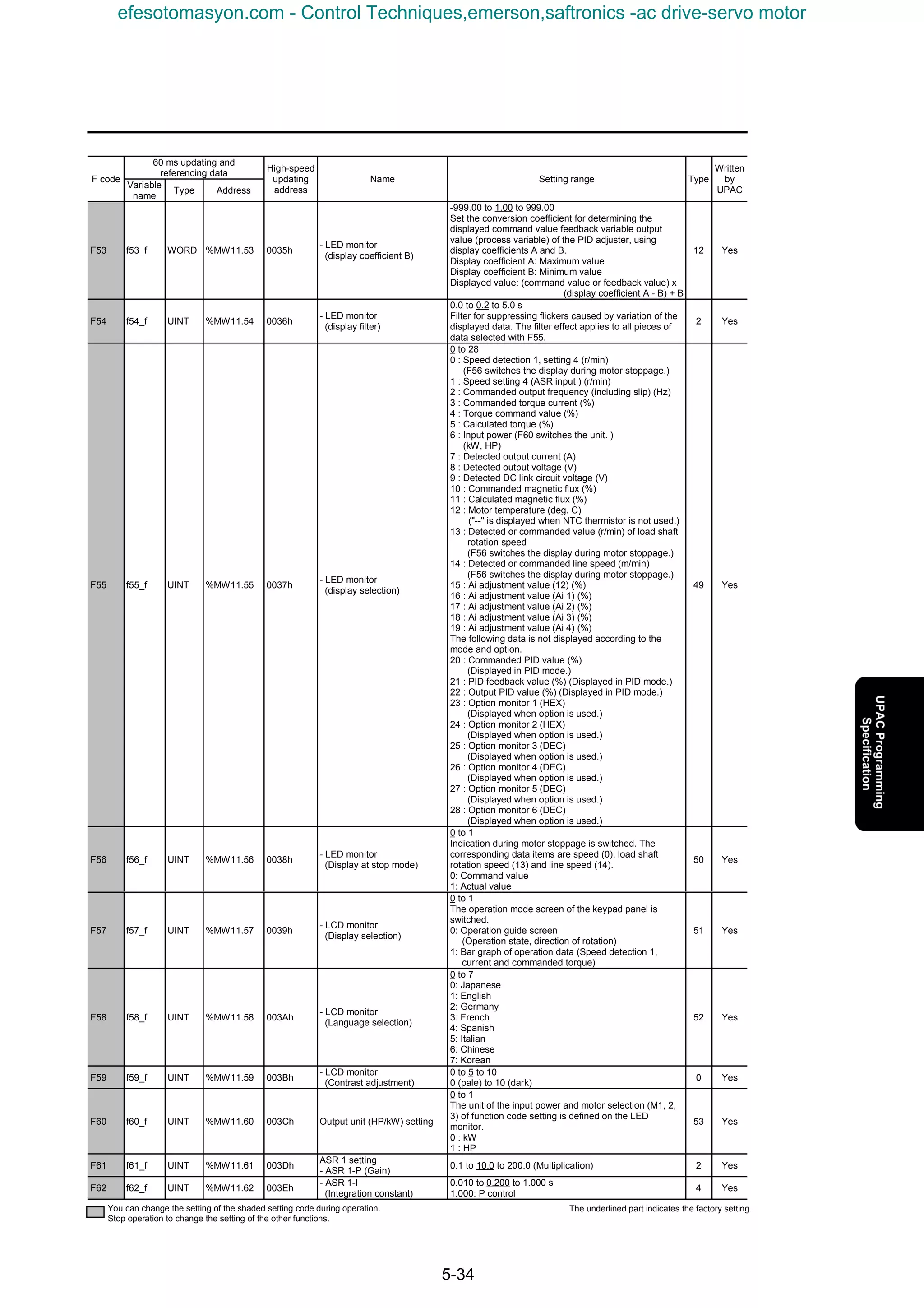
![5. UPAC Programming Specification
5-35
60 ms updating and
referencing data
F code
Variable
name
Type Address
High-speed
updating
address
Name Setting range Type
Written
by
UPAC
F63 f63_f UINT %MW11.63 003Fh - ASR 1-FF (Gain) 0.000 to 9.999 s 4 Yes
F64 f64_f UINT %MW11.64 0040h - ASR 1 input filter 0.000 to 0.040 to 5.000 s 4 Yes
F65 f65_f UINT %MW11.65 0041h - ASR 1 detection filter 0.000 to 0.005 to 0.100 s 4 Yes
F66 f66_f UINT %MW11.66 0042h - ASR 1 output filter 0.000 to 0.002 to 0.100 s 4 Yes
F67 f67_f UINT %MW11.67 0043h
- S-curve
(Acceleration start side 1)
0 to 50 % 0 Yes
F68 f68_f UINT %MW11.68 0044h
- S-curve
(Acceleration end side 1)
0 to 50 % 0 Yes
F69 f69_f UINT %MW11.69 0045h
- S-curve
(Deceleration start side 1)
0 to 50 % 0 Yes
F70 f70_f UINT %MW11.70 0046h
- S-curve
(Deceleration end side 1)
0 to 50 % 0 Yes
F73 f73_f UINT %MW11.73 0049h
Magnetic flux level setting
- Magnetic flux level at light
load
10 to 100 % 16 Yes
F74 f74_f UINT %MW11.74 004Ah - Pre-exciting time 0.0 to 10.0 s 2 Yes
F75 f75_f UINT %MW11.75 004Bh - Pre-excitation initial level 100 to 400 % 0 Yes
F76 f76_f UINT %MW11.76 004Ch
Speed limit setting
- Speed limit (Mode selection)
0 to 3
0 : Limit level 1 for forward rotation and limit level 2 for
reverse rotation
1 : Limit level 1 for both forward and reverse rotation
2 : Limit level 1 for upper limit and limit level 2 for lower
limit
3 : Limit level 1 for forward rotation and limit level 2 for
reverse rotation. Add the [12] input as a bias.
91 Yes
F77 f77_f INT %MW11.77 004Dh - Speed limit level 1 -110.0 to 100.0 to 110.0 % 6 Yes
F78 f78_f INT %MW11.78 004Eh - Speed limit level 2 -110.0 to 100.0 to 110.0 % 6 Yes
F79 f79_f UINT %MW11.79 004Fh Motor selection (M1, M2, M3)
0 to 2
The effective motor (M1, 2 or 3) is selected with the
function code or contact.
0 : M1 selection
However, the contact switching is given priority.
M1 selection : (MCH2, MCH3) = (OFF, OFF) (ON, ON)
(without assignment)
M2 selection : (MCH2, MCH3) = (ON, OFF)
M3 selection : (MCH2, MCH3) = (OFF, ON)
1 : M2 selection (X function invalid)
2 : M3 selection (X function invalid)
54 Yes
F80 f80_f UINT %MW11.80 0050h Current rating switching
0 to 2
0 : CT (Overload current 150%)
1 : VT (Overload current 110%)
2 : HT (Overload torque 200/170%)
56 Yes
You can change the setting of the shaded setting code during operation.
Stop operation to change the setting of the other functions.
The underlined part indicates the factory setting.
efesotomasyon.com - Control Techniques,emerson,saftronics -ac drive-servo motor](https://image.slidesharecdn.com/vg7upacmanual-140613044924-phpapp01/75/Vg7-upac-manual-239-2048.jpg)
![5-36
Table 5-2-39 E: Extension Terminal Functions
60 ms updating and
referencing data
F code
Variable
name
Type Address
High-speed
updating
address
Name Setting range Type
Written
by
UPAC
E01 e01_f UINT %MW11.97 0101h
X terminal function
- X1 terminal function
0 to 63
0, 1, 2, 3 : Multistep speed selection
(1 to 15 steps) [0:SS1, 1:SS2, 2:SS4, 3:SS8]
4, 5 : ASR, acceleration / deceleration selection
(4 steps) [4:RT1, 5:RT2]
6 : 3 wire operation stop command [HLD]
7 : Coast-to-stop command [BX]
8 : Alarm reset [RST]
9 : External alarm [THR]
10 : Jogging operation [JOG]
11 : Speed setting N2 / speed setting N1 [N2 / N1]
12 : Motor M2 selection [M-CH2]
13 : Motor M3 selection [M-CH3]
14 : DC brake command [DCBRK]
15 : ACC/DEC cleared to zero [CLR]
16 : Creep speed switching in UP/DOWN control
[CRP-N2 /N1]
17 : UP command in UP/DOWN control [UP]
18 : DOWN command in UP/DOWN control [DOWN]
19 : Write enable for keypad [WE-KP]
20 : PID control cancel [KP / PID]
21 : Inverse mode changeover [IVS]
22 : Interlock (52-2) [IL]
23 : Write enable through link [WE-LK]
24 : Operation selection through link [LE]
25 : Universal DI [U-DI]
26 : Pickup start mode [STM]
27 : Synchronized operation command
(PG (PR) option) [SYC]
28 : Zero speed locking command [LOCK]
29 : Pre-exciting command [EXITE]
30 : Speed reference value limiter cancel
(relevant codes: F76, F77, F78) [N-LIM]
31 : H41 [torque command] cancel [H41-CCL]
32 : H42 [torque current command] cancel [H42-CCL]
33 : H43 [magnetic flux command] cancel [H43-CCL]
34 : F40 [torque limiting mode 1] cancel [H40-CCL]
35 : Torque limit (level 1 / 2 selection)[TL2 / TL1]
36 : Bypass [BPS]
37, 38 : Torque bias command 1 / 2 [37:TB1, 38:TB2]
39 : Droop selection [DROOP]
40 : Ai 1 zero hold [ZH-AI1]
41 : Ai 2 zero hold [ZH-AI2]
42 : Ai 3 zero hold (AIO option) [ZH-AI3]
43 : Ai 4 zero hold (AIO option) [ZH-AI4]
44 : Ai 1 polarity inversion [REV-AI1]
45 : Ai 2 polarity inversion [REV-AI2]
46 : Ai 3 polarity inversion (AIO option) [REV-AI3]
47 : Ai 4 polarity inversion (AIO option) [REV-AI4]
48 : PID output inversion selection [PID-INV]
49 : PG alarm cancel [PG-CCL]
50 : Under voltage cancel [LU-CCL]
51 : Ai torque bias hold [H-TB]
52 : STOP 1
(The motor decelerates and stops in normal
deceleration time.) [STOP1]
53 : STOP 2
(The motor decelerates and stops in “deceleration
time 4.”) [STOP2]
54 : STOP 3
(The motor decelerates and stops with max. torque
without relations to deceleration time setting.)
[STOP3]
55 : DIA data latch (DIA option) [DIA]
56 : DIB data latch (DIB option) [DIB]
57 : Multi-winding motor cancel
(SI (MWS) option) [MT-CCL]
58, 59, 60, 61, 62, 63: OptionDi 1/2/3/4/5/6 [0-DI1 to 6]
57 Yes
E02 e02_f UINT %MW11.98 0102h - X2 terminal function 0 to 1 to 63 (Refer to X1 terminal function.) 57 Yes
E03 e03_f UINT %MW11.99 0103h - X3 terminal function 0 to 2 to 63 (Refer to X1 terminal function.) 57 Yes
E04 e04_f UINT %MW11.100 0104h - X4 terminal function 0 to 3 to 63 (Refer to X1 terminal function.) 57 Yes
E05 e05_f UINT %MW11.101 0105h - X5 terminal function 0 to 4 to 63 (Refer to X1 terminal function.) 57 Yes
E06 e06_f UINT %MW11.102 0106h - X6 terminal function 0 to 5 to 63 (Refer to X1 terminal function.) 57 Yes
E07 e07_f UINT %MW11.103 0107h - X7 terminal function 0 to 7 to 63 (Refer to X1 terminal function.) 57 Yes
E08 e08_f UINT %MW11.104 0108h - X8 terminal function 0 to 8 to 63 (Refer to X1 terminal function.) 57 Yes
E09 e09_f UINT %MW11.105 0109h - X9 terminal function 0 to 9 to 63 (Refer to X1 terminal function.) 57 Yes
E10 e10_f UINT %MW11.106 010Ah - X11 terminal function 0 to 25 to 63 (Refer to X1 terminal function.) 57 Yes
E11 e11_f UINT %MW11.107 010Bh - X12 terminal function 0 to 25 to 63 (Refer to X1 terminal function.) 57 Yes
E12 e12_f UINT %MW11.108 010Ch - X13 terminal function 0 to 25 to 63 (Refer to X1 terminal function.) 57 Yes
E13 e13_f UINT %MW11.109 010Dh - X14 terminal function 0 to 25 to 63 (Refer to X1 terminal function.) 57 Yes
E14 e14_f WORD %MW11.110 010Eh
X terminal function normally
open/closed
0000 to 01FF
Designate the normal state of X1 through X9.
0 : Normally open
1 : Normally closed
35 Yes
You can change the setting of the shaded setting code during operation.
Stop operation to change the setting of the other functions.
The underlined part indicates the factory setting.
efesotomasyon.com - Control Techniques,emerson,saftronics -ac drive-servo motor](https://image.slidesharecdn.com/vg7upacmanual-140613044924-phpapp01/75/Vg7-upac-manual-240-2048.jpg)
![5. UPAC Programming Specification
5-37
60 ms updating and referencing
data
F code
Variable
name
Type Address
High-speed
updating
address
Name Setting range Type
Written
by
UPAC
E15 e15_f UINT %MW11.111 010Fh
Y terminal function
- Y1 terminal function
0 to 1 to 47 0 : Inverter running [RUN]
1 : Speed existence [N-EX]
2 : Speed agreement [N-AG]
3 : Speed arrival [N-AR]
4 : Speed detection 1 [N-DT1]
5 : Speed detection 2 [N-DT2]
6 : Speed detection 3 [N-DT3]
7 : Stopped upon under voltage [LU]
8 : Torque polarity detection (braking / driving) [B/D]
9 : Torque limiting [TL]
10 : Torque detection 1 [T-DT1]
11 : Torque detection 2 [T-DT2]
12 : Keypad operation mode [KP]
13 : Inverter stopping [STOP]
14 : Operation ready [RDY]
15 : Magnetic flux detection signal [MF-DT]
16 : Motor M2 selection status [SW-M2]
17 : Motor M3 selection status [SW-M3]
18 : Brake release signal [BRK]
19 : Alarm indication [AL1]
20 : Alarm indication [AL2]
21 : Alarm indication [AL4]
22 : Alarm indication [AL8]
23 : Cooling fan operation [FAN]
24 : Auto-resetting [TRY]
25 : Universal DO [U-DO]
26 : Heat sink overheat early warning[INV-OH]
27 : Synchronization completion [SY-C]
28 : Life alarm [LIFE]
29 : Accelerating [U-ACC]
30 : Decelerating [U-DEC]
31 : Inverter overload early warning [INV-OL]
32 : Motor overheat early warning [M-OH]
33 : Motor overload early warning [M-OL]
34 : DB overload early warning [DB-OL]
35 : Link transmission error [LK-ERR]
36 : Load adaptive control being limited [ANL]
37 : Load adaptive control being calculated [ANC]
38 : Analog torque bias hold [TBH]
39 to 47 : Option Do 1 to 9 [O-DO1 to O-DO9]
58 Yes
E16 e16_f UINT %MW11.112 0110h - Y2 terminal function 0 to 2 to 47 (Refer to Y1 terminal function.) 58 Yes
E17 e17_f UINT %MW11.113 0111h - Y3 terminal function 0 to 3 to 47 (Refer to Y1 terminal function.) 58 Yes
E18 e18_f UINT %MW11.114 0112h - Y4 terminal function 0 to 4 to 47 (Refer to Y1 terminal function.) 58 Yes
E19 e19_f UINT %MW11.115 0113h - Y5 terminal function 0 to 14 to 47 (Refer to Y1 terminal function.) 58 Yes
E20 e20_f UINT %MW11.116 0114h - Y11 terminal function 0 to 26 to 47 (Refer to Y1 terminal function.) 58 Yes
E21 e21_f UINT %MW11.117 0115h - Y12 terminal function 0 to 26 to 47 (Refer to Y1 terminal function.) 58 Yes
E22 e22_f UINT %MW11.118 0116h - Y13 terminal function 0 to 26 to 47 (Refer to Y1 terminal function.) 58 Yes
E23 e23_f UINT %MW11.119 0117h - Y14 terminal function 0 to 26 to 47 (Refer to Y1 terminal function.) 58 Yes
E24 e24_f UINT %MW11.120 0118h - Y15 terminal function 0 to 26 to 47 (Refer to Y1 terminal function.) 58 Yes
E25 e25_f UINT %MW11.121 0119h - Y16 terminal function 0 to 26 to 47 (Refer to Y1 terminal function.) 58 Yes
E26 e26_f UINT %MW11.122 011Ah - Y17 terminal function 0 to 26 to 47 (Refer to Y1 terminal function.) 58 Yes
E27 e27_f UINT %MW11.123 011Bh - Y18 terminal function 0 to 26 to 47 (Refer to Y1 terminal function.) 58 Yes
E28 e28_f WORD %MW11.124 011Ch
Y terminal function normally
open/closed
0000 to 001F
Set the normal state of Y1 through Y5.
0 : Normally open
1 : Normally closed
36 Yes
E29 e29_f UINT %MW11.125 011Dh PG pulse output selection
0 to 9
0 : No division
1 : 1/2
2 : 1/4
3 : 1/8
4 : 1/16
5 : 1/32
6 : 1/64
0 to 6 : Inputs to built-in PG are divided and output.
7 : Pulse oscillation mode (AB 90° phase difference)
Internal speed command is converted into pulses and
output.
8 : PG (PD)
Position detection pulse input is output as it is.
9 : PG (PR)
The position command pulse input is output as it is.
92 Yes
E30 e30_f UINT %MW11.126 011Eh
Protective function setting
- Motor overheat protection
(temp.)
100 to 150 to 200 °C
Valid when NTC thermistor is used for selected motor
(M1 or M2) or when motor temperature [M-TMP] is
selected with analog input.
0 Yes
E31 e31_f UINT %MW11.127 011Fh
- Motor overheat early
warning (temp.)
50 to 75 to 200 °C
Valid when NTC thermistor is used for selected motor
(M1 or M2) or when motor temperature [M-TMP] is
selected with analog input.
0 Yes
E32 e32_f UINT %MW11.128 0120h
- M1 to M3 PTC operation
level
0.00 to 1.60 to 5.00 V 3 Yes
E33 e33_f UINT %MW11.129 0121h
- Inverter overload early
warning
25 to 90 to 100 % 0 Yes
E34 e34_f UINT %MW11.130 0122h
- Motor overload early
warning
25 to 90 to 100 % 0 Yes
E35 e35_f UINT %MW11.131 0123h - DB overload protection 0 to 10 to 100 % 0 Yes
You can change the setting of the shaded setting code during operation.
Stop operation to change the setting of the other functions.
The underlined part indicates the factory setting.
efesotomasyon.com - Control Techniques,emerson,saftronics -ac drive-servo motor](https://image.slidesharecdn.com/vg7upacmanual-140613044924-phpapp01/75/Vg7-upac-manual-241-2048.jpg)
![5-38
60 ms updating and
referencing data
F code
Variable
name
Type Address
High-speed
updating
address
Name Setting range Type
Written
by
UPAC
E36 e36_f UINT %MW11.132 0124h - DB overload early warning 0 to 80 to 100 % 0 Yes
E37 e37_f UINT %MW11.133 0125h - DB thermal time constant 0 to 300 to 1000 s 0 Yes
E38 e38_f WORD %MW11.134 0126h
Speed detection setting
- Speed detection method
000 to 111
(Detection method of E39) (Detection method of E40)
(Detection method of E41)
0 : Speed detection
1 : Speed setting
The command value only is valid during V/f control.
9 Yes
E39 e39_f UINT %MW11.135 0127h - Speed detection level 1 0 to 1500 to 24000 r/min 0 Yes
E40 e40_f INT %MW11.136 0128h - Speed detection level 2 -24000 to 1500 to 24000 r/min 5 Yes
E41 e41_f INT %MW11.137 0129h - Speed detection level 3 -24000 to 1500 to 24000 r/min 5 Yes
E42 e42_f UINT %MW11.138 012Ah - Speed arrival (hysteresis) 1.0 to 3.0 to 20.0 % 2 Yes
E43 e43_f UINT %MW11.139 012Bh
- Speed agreement
(hysteresis)
1.0 to 3.0 to 20.0 % 2 Yes
E44 e44_f UINT %MW11.140 012Ch
- Speed agreement
(off-delay timer)
0.000 to 0.100 to 1.000 s 4 Yes
E45 e45_f UINT %MW11.141 012Dh - Speed disagreement alarm
0 to 21
Units digit: speed disagreement alarm (Er9)
0 : Not used
1 : Used
Tenth digit : Lin phase lack detection
0 : No-DCR level
1 : DCR level
2 : For manufacturer (Do not specify.)
9 Yes
E46 e46_f UINT %MW11.142 012Eh
Torque / magnetic flux
detection level setting
- Torque detection level 1
0 to 30 to 300 %
Calculated value during V/f control
16 Yes
E47 e47_f UINT %MW11.143 012Fh - Torque detection level 2
0 to 30 to 300 %
Calculated value during V/f control
16 Yes
E48 e48_f UINT %MW11.144 0130h - Magnetic flux detection level 10 to 100 % 16 Yes
E49 e49_f UINT %MW11.145 0131h
Ai terminal function
- Ai1 terminal function
0 to 18
0 : Input signal shutoff [OFF] -
1 : Auxiliary speed setting 1 [AUX-N1] ±10V/±Nmax
2 : Auxiliary speed setting 2 [AUX-N2] ±10V/±Nmax
3 : Torque limit (level 1) [TL-REF1]±10V/±150%
4 : Torque limit (level 2) [TL-REF2]±10V/±150%
5 : Torque bias [TB-REF] ±10V/±150%
6 : Torque command [T-REF] ±10V/±150%
7 : Torque current command [IT-REF] ±10V/±150%
8 : Creep speed 1 in UP/DOWN control
[CRP-N1] ±10V/±Nmax
9 : Creep speed 2 in UP/DOWN control
[CRP-N2] ±10V/±Nmax
10 : Magnetic flux command [MF-REF] ±10V/±100%
11 : Line speed detection [LINE-N] ±10V/±Nmax
12 : Motor temperature [M-TMP] ±10V/200°C
13 : Speed override [N-OR] ±10V/±50%
14 : Universal Ai [U-AI] ±10V/±4000(h)
15 : PID feedback value [PID-FB] ±10V/±20000(d)
16 : PID reference value [PID-REF] ±10V/±20000(d)
17 : PID correction gain [PID-G] ±10V/±4000(h)
18 : Option Ai [O-AI] ±10V/±7FFF(h)
59 Yes
E50 e50_f UINT %MW11.146 0132h - Ai2 terminal function 0 to 18 (Refer to Ai1 terminal function.) 59 Yes
E51 e51_f UINT %MW11.147 0133h - Ai3 terminal function
0 to 18 (Refer to Ai1 terminal function.)
(Displayed for models with AIO option.)
59 Yes
E52 e52_f UINT %MW11.148 0134h - Ai4 terminal function
0 to 18 (Refer to Ai1 terminal function.)
(Displayed for models with AIO option.)
59 Yes
E53 e53_f INT %MW11.149 0135h
Ai gain setting
- Ai1 gain setting
-10.000 to 1.000 to 10.000 (Multiplication.) 8 Yes
E54 e54_f INT %MW11.150 0136h - Ai2 gain setting -10.000 to 1.000 to 10.000 (Multiplication.) 8 Yes
E55 e55_f INT %MW11.151 0137h - Ai3 gain setting
-10.000 to 1.000 to 10.000 (Multiplication.)
(Displayed for models with AIO option)
8 Yes
E56 e56_f INT %MW11.152 0138h - Ai4 gain setting
-10.000 to 1.000 to 10.000 (Multiplication.)
(Displayed for models with AIO option.)
8 Yes
E57 e57_f INT %MW11.153 0139h
Ai bias setting
- Ai1 bias setting
-100.0 to 0.0 to 100.0 % 6 Yes
E58 e58_f INT %MW11.154 013Ah - Ai2 bias setting -100.0 to 0.0 to 100.0 % 6 Yes
E59 e59_f INT %MW11.155 013Bh - Ai3 bias setting
-100.0 to 0.0 to 100.0 %
(Displayed for models with AIO option.)
6 Yes
E60 e60_f INT %MW11.156 013Ch - Ai4 bias setting
-100.0 to 0.0 to 100.0 %
(Displayed for models with AIO option.)
6 Yes
E61 e61_f UINT %MW11.157 013Dh
Ai filter setting
- Ai1 filter setting
0.000 to 0.010 to 0.500 s 4 Yes
E62 e62_f UINT %MW11.158 013Eh - Ai2 filter setting 0.000 to 0.010 to 0.500 s 4 Yes
E63 e63_f UINT %MW11.159 013Fh - Ai3 filter setting
0.000 to 0.010 to 0.500 s
(Displayed for models with AIO option.)
4 Yes
E64 e64_f UINT %MW11.160 0140h - Ai4 filter setting
0.000 to 0.010 to 0.500 s
(Displayed for models with AIO option.)
4 Yes
E65 e65_f UINT %MW11.161 0141h
Increment / decrement limiter
(Ai) setting
- Increment / decrement
limiter (Ai1)
0.00 to 60.00 s 3 Yes
E66 e66_f UINT %MW11.162 0142h
- Increment / decrement
limiter (Ai2)
0.00 to 60.00 s 3 Yes
E67 e67_f UINT %MW11.163 0143h
- Increment / decrement
limiter (Ai3)
0.00 to 60.00 s
(Displayed for models with AIO option.)
3 Yes
E68 e68_f UINT %MW11.164 0144h
- Increment / decrement
limiter (Ai4)
0.00 to 60.00 s
(Displayed for models with AIO option.)
3 Yes
You can change the setting of the shaded setting code during operation.
Stop operation to change the setting of the other functions.
The underlined part indicates the factory setting.
efesotomasyon.com - Control Techniques,emerson,saftronics -ac drive-servo motor](https://image.slidesharecdn.com/vg7upacmanual-140613044924-phpapp01/75/Vg7-upac-manual-242-2048.jpg)
![5. UPAC Programming Specification
5-39
60 ms updating and referencing
data
F code
Variable
name
Type Address
High-speed
updating
address
Name Setting range Type
Written
by
UPAC
E69 e69_f UINT %MW11.165 0145h
AO terminal function setting
- AO1 terminal function
0 to 1 to 31
0 : Detected speed 1
(speedometer, swing on single side)
[N-FB1+] ±Nmax/10V
1 : Detected speed 1
(speedometer, swing on both sides)
[N-FB1±] ±Nmax/±10V
2 : Speed setting 2
(before acceleration / deceleration calculation)
[N-REF2] ±Nmax/±10V
3 : Speed setting 4 (ASR input)
[N-REF4] ±Nmax/±10V
4 : Detected speed 2 (ASR input)
[N-FB2±] ±Nmax/±10V
5 : Detected line speed [LINE-N±] ±Nmax/±10V
6 : Torque current command
(torque ammeter, swing on both sides)
[IT-REF±] ±150%/±10V
7 : Torque current command
(torque ammeter, swing on single side)
[IT-REF+] ±150%/10V
8 : Torque command
(torque meter, swing on both sides)
[T-REF±] ±150%/±10V
9 : Torque command
(torque meter, swing on single side)
[T-REF+] ±150%/10V
10 : Motor current [I-AC] 200%/10V
11 : Motor voltage [V-AC] 200%/10V
12 : Input power [PWR] 200%/10V
13 : DC link circuit voltage [V-DC]800V/10V
14 : +10V output test [P10], output equivalent to +10V
15 : -10V output test [N10], output equivalent to -10V
60 Yes
E70 e70_f UINT %MW11.166 0146h - AO2 terminal function 0 to 6 to 31 (Refer to AO1 terminal function.) 60 Yes
E71 e71_f UINT %MW11.167 0147h - AO3 terminal function 0 to 3 to 31 (Refer to AO1 terminal function.) 60 Yes
E72 e72_f UINT %MW11.168 0148h - AO4 terminal function
0 to 31 (Refer to AO1 terminal function.)
(Displayed for models with AIO option.)
60 Yes
E73 e73_f UINT %MW11.169 0149h - AO5 terminal function
0 to 31 (Refer to AO1 terminal function.)
(Displayed for models with AIO option.)
60 Yes
E74 e74_f INT %MW11.170 014Ah
AO gain setting
- AO1 gain setting
-100.00 to 1.00 to 100.00 ((Multiplication) 7 Yes
E75 e75_f INT %MW11.171 014Bh - AO2 gain setting -100.00 to 1.00 to 100.00 (Multiplication) 7 Yes
E76 e76_f INT %MW11.172 014Ch - AO3 gain setting -100.00 to 1.00 to 100.00 (Multiplication) 7 Yes
E77 e77_f INT %MW11.173 014Dh - AO4 gain setting
-100.00 to 1.00 to 100.00 (Multiplication)
(Displayed for models with AIO option.)
7 Yes
E78 e78_f INT %MW11.174 014Eh - AO5 gain setting
-100.00 to 1.00 to 100.00 (Multiplication)
(Displayed for models with AIO option.)
7 Yes
E79 e79_f INT %MW11.175 014Fh
AO bias setting
- AO1 bias setting
-100.0 to 0.0 to 100.0 % 6 Yes
E80 e80_f INT %MW11.176 0150h - AO2 bias setting -100.0 to 0.0 to 100.0 % 6 Yes
E81 e81_f INT %MW11.177 0151h - AO3 bias setting -100.0 to 0.0 to 100.0 % 6 Yes
E82 e82_f INT %MW11.178 0152h - AO4 bias setting
-100.0 to 0.0 to 100.0 %
(Displayed for models with AIO option)
6 Yes
E83 e83_f INT %MW11.179 0153h - AO5 bias setting
-100.0 to 0.0 to 100.0 %
(Displayed for models with AIO option)
6 Yes
E84 e84_f UINT %MW11.180 0154h AO1-5 filter setting 0.000 to 0.010 to 0.500 s 4 Yes
Table 5-2-40 C: Control Functions of Frequency
60 ms updating and
referencing data
F code
Variable
name
Type Address
High-speed
updating
address
Name Setting range Type
Written
by
UPAC
C01 c01_f UINT %MW11.193 0201h
Jump speed setting
- Jump speed 1
0 to 24000 r/min 0 Yes
C02 c02_f UINT %MW11.194 0202h - Jump speed 2 0 to 24000 r/min 0 Yes
C03 c03_f UINT %MW11.195 0203h - Jump speed 3 0 to 24000 r/min 0 Yes
C04 c04_f UINT %MW11.196 0204h - Jump width 0 to 1000 r/min 0 Yes
C05 c05_f UINT %MW11.197 0205h
Multistep speed setting
- Multistep speed 1
0 to 24000 r/min / 0.00 to 100.00 % / 0.0 to 999.9 m/min
(Switched according to C21.)
0 Yes
C06 c06_f UINT %MW11.198 0206h - Multistep speed 2
0 to 24000 r/min / 0.00 to 100.00 % / 0.0 to 999.9 m/min
(Switched according to C21.)
0 Yes
C07 c07_f UINT %MW11.199 0207h - Multistep speed 3
0 to 24000 r/min / 0.00 to 100.00 % / 0.0 to 999.9 m/min
(Switched according to C21.)
0 Yes
C08 c08_f UINT %MW11.200 0208h - Multistep speed 3
0 to 24000 r/min / 0.00 to 100.00 % / 0.0 to 999.9 m/min
(Switched according to C21.)
0 Yes
C09 c09_f UINT %MW11.201 0209h - Multistep speed 5
0 to 24000 r/min / 0.00 to 100.00 % / 0.0 to 999.9 m/min
(Switched according to C21.)
0 Yes
C10 c10_f UINT %MW11.202 020Ah - Multistep speed 6
0 to 24000 r/min / 0.00 to 100.00 % / 0.0 to 999.9 m/min
(Switched according to C21.)
0 Yes
C11 c11_f UINT %MW11.203 020Bh - Multistep speed 7
0 to 24000 r/min / 0.00 to 100.00 % / 0.0 to 999.9 m/min
(Switched according to C21.)
0 Yes
C12 c12_f UINT %MW11.204 020Ch - Multistep speed 8
0 to 24000 r/min / 0.00 to 100.00 % / 0.0 to 999.9 m/min
(Switched according to C21.)
0 Yes
You can change the setting of the shaded setting code during operation.
Stop operation to change the setting of the other functions.
The underlined part indicates the factory setting.
efesotomasyon.com - Control Techniques,emerson,saftronics -ac drive-servo motor](https://image.slidesharecdn.com/vg7upacmanual-140613044924-phpapp01/75/Vg7-upac-manual-243-2048.jpg)
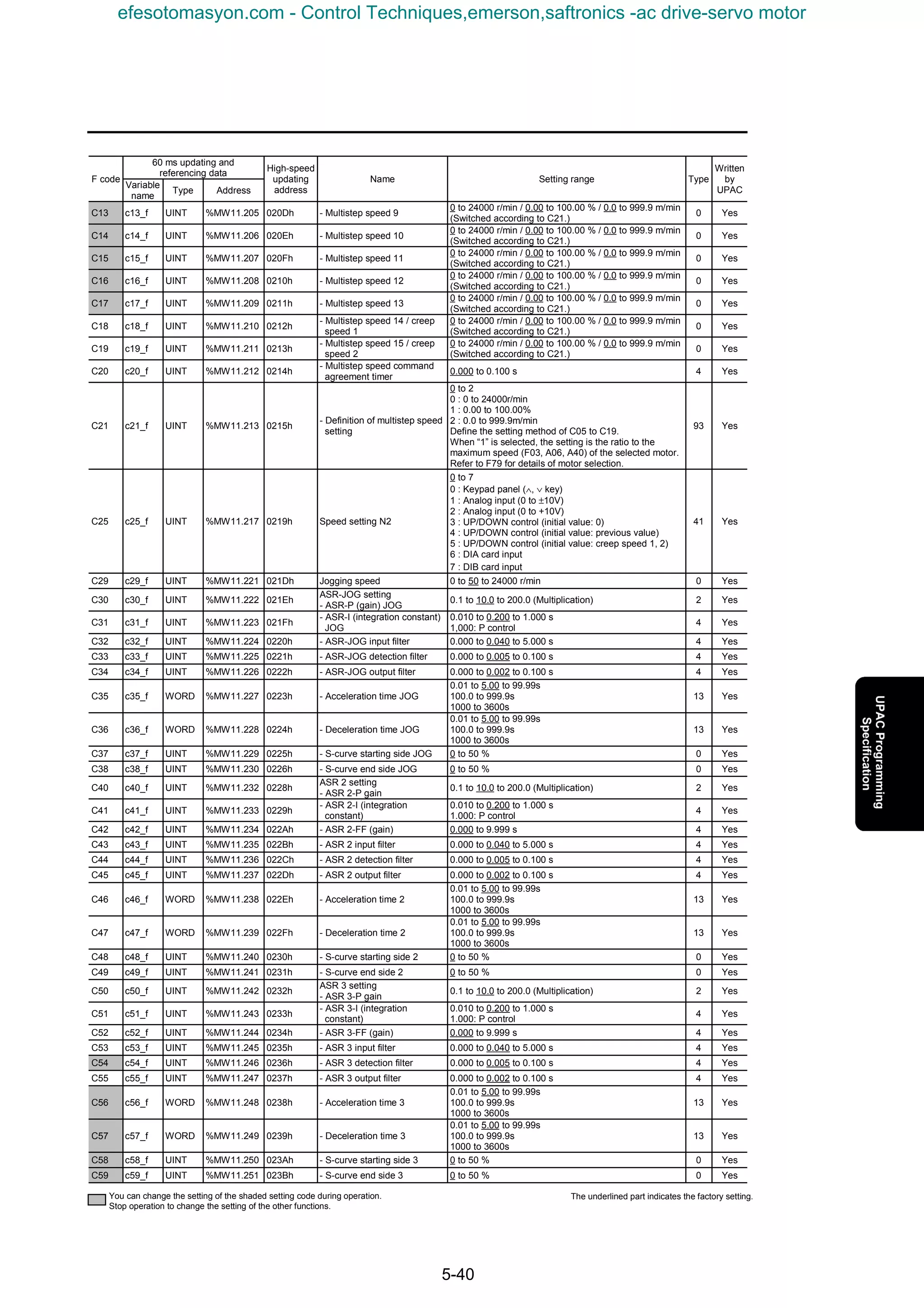
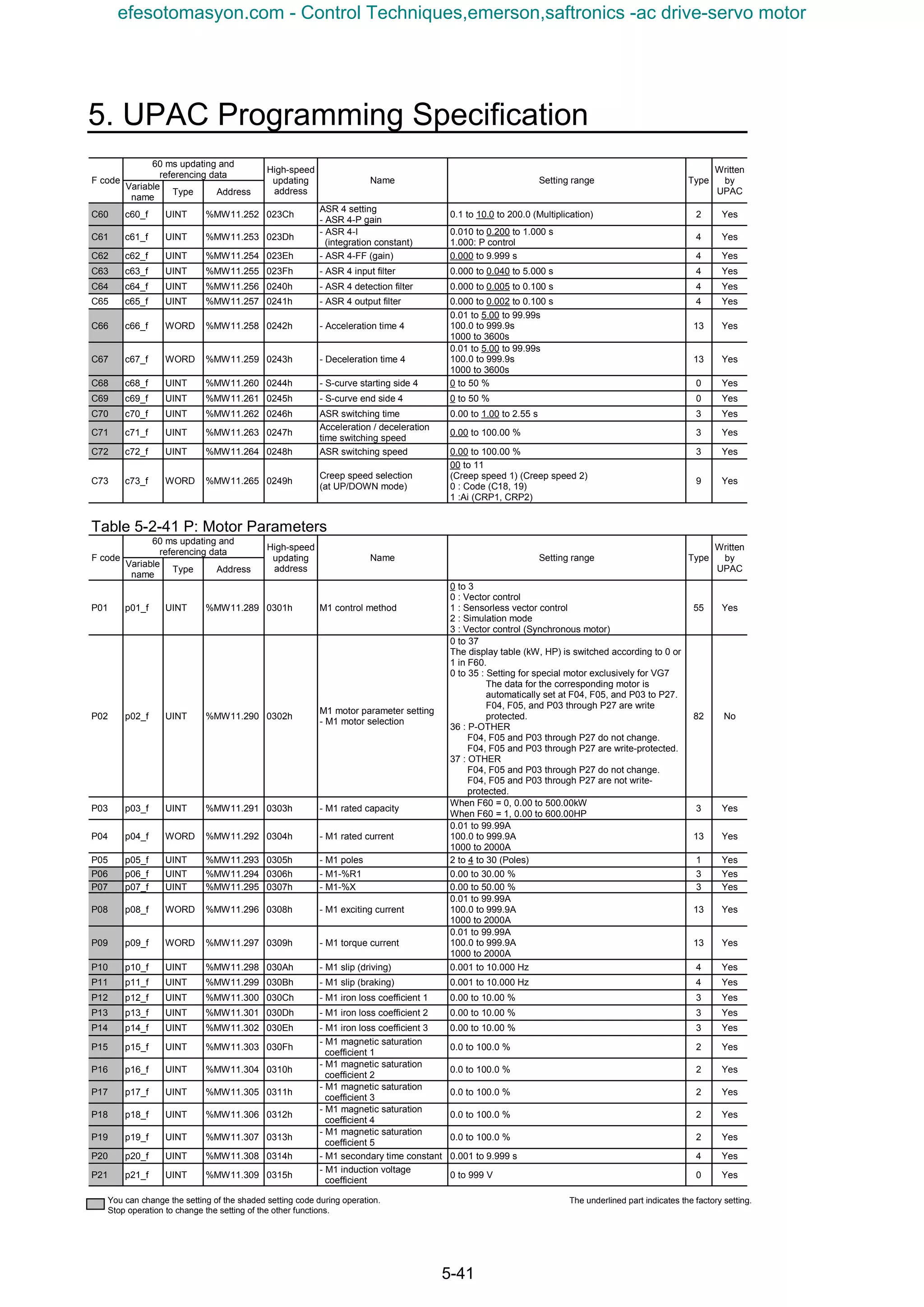
![5-42
60 ms updating and
referencing data
F code
Variable
name
Type Address
High-speed
updating
address
Name Setting range Type
Written
by
UPAC
P22 p22_f UINT %MW11.310 0316h
- M1 - R2 correction
coefficient 1
0.500 to 5.000 4 Yes
P23 p23_f UINT %MW11.311 0317h
- M1 - R2 correction
coefficient 2
0.500 to 5.000 4 Yes
P24 p24_f UINT %MW11.312 0318h
- M1 - R2 correction
coefficient 3
0.010 to 5.000 4 Yes
P25 p25_f UINT %MW11.313 0319h
- M1 exciting current
correction coefficient
0.000 to 5.000 4 Yes
P26 p26_f UINT %MW11.314 031Ah - M1 - ACR-P (gain) 0.1 to 20.0 2 Yes
P27 p27_f UINT %MW11.315 031Bh - M1 - ACR-I (integration time) 0.5 to 100.0 ms 2 Yes
P28 p28_f UINT %MW11.316 031Ch M1-PG pulses 100 to 1024 to 60000 0 Yes
P29 p29_f WORD %MW11.317 031Dh
M1 external PG correction
coefficient
0000 to 4000 to 4FFF 9 Yes
P30 p30_f UINT %MW11.318 031Eh M1 thermistor selection
0 to 1 to 3
0: No thermistor
1: NTC thermistor selection
2: PTC thermistor selection
3: Ai [M-TMP]
Set the protection level of the motor
84 Yes
Table 5-2-42 H: High Performance Functions
60 ms updating and
referencing data
F code
Variable
name
Type Address
High-speed
updating
address
Name Setting range Type
Written
by
UPAC
H01 h01_f UINT %MW11.321 0401h Tuning operation selection
0 to 4: Automatically reset to zero after data is written.
0 : Inactive
1 : ASR auto tuning
2 : Motor auto tuning; R1, Lσ
3 : Motor stoppage auto tuning
4 : Motor rotation auto tuning
The data after tuning evaporates when the power is
turned off. To retain the data, validate H02 (all save
function).
61 No
H02 h02_f UINT %MW11.322 0402h All save function
0 to 1
If H01 (auto tuning) is used to change internal data, or if
data is changed through the link (TLINK, field path,
RS485, etc.), the data evaporates when the inverter is
turned off. To retain data, activate this function.
The setting is automatically reset to zero after data is
written.
11 No
H03 h03_f UINT %MW11.323 0403h Data initialization
0 to 1
The data changed by the customer is initialized to the
default factory setting.
The initialized code includes all the F, E, C, H, o, L and
U codes excluding the motor parameters (P and A),
F04, F05, and F10 through F12.
The setting is automatically reset to zero after the data
is written.
11 No
H04 h04_f UINT %MW11.324 0404h Retry (times)
0 to 10
0 : Inactive
1 to 10 times
The retry operation signal can be output to the output
terminal.。
0 Yes
H05 h05_f UINT %MW11.325 0405h Retry (interval) 0.01 to 5.00 to 20.00 s 3 Yes
H06 h06_f UINT %MW11.326 0406h Cooling fan ON/OFF control
0 to 1
The cooling fan inside the inverter is detected for
automatic ON/OFF control of the cooling fan. The fan
always rotates if “inactive” is selected.
0 : Inactive
1 : Active
The cooling fan operation signal can be output in
interlock with this function.
68 Yes
H08 h08_f UINT %MW11.328 0408h Reverse phase sequence lock
0 to 1
0: Ineffective
1: Effective
68 Yes
H09 h09_f UINT %MW11.329 0409h
Starting characteristic
(rotating motor pick-up)
0 to 2
0: Inactive
1: Active (only when restarting after momentary power
failure)
2: Active
Fixed at inactive during V/f control.
0 Yes
H10 h10_f UINT %MW11.330 040Ah
Automatic energy-saving
operation
0 to 1
0: Ineffective
1: Effective
68 Yes
H11 h11_f UINT %MW11.331 040Bh
Automatic operation OFF
function
0 to 2
Operation is automatically stopped at a speed lower
than the stopping speed setting.
0: Operation OFF upon disconnection across FWD-CM,
REV-CM
1: Operation OFF at speeds lower than F37 stopping
speed even if connection across FWD-CM and REV-
CM is ON.
2: Coast-to-stop upon disconnection across FWD-CM or
REV-CM.
0 Yes
You can change the setting of the shaded setting code during operation.
Stop operation to change the setting of the other functions.
The underlined part indicates the factory setting.
efesotomasyon.com - Control Techniques,emerson,saftronics -ac drive-servo motor](https://image.slidesharecdn.com/vg7upacmanual-140613044924-phpapp01/75/Vg7-upac-manual-246-2048.jpg)
![5. UPAC Programming Specification
5-43
60 ms updating and
referencing data
F code
Variable
name
Type Address
High-speed
updating
address
Name Setting range Type
Written
by
UPAC
H13 h13_f UINT %MW11.333 040Dh
Start after momentary power
failure
- Delay
0.1 to 0.5 to 5.0 s 2 Yes
H14 h14_f UINT %MW11.334 040Eh - Speed fall rate 1 to 500 to 3600 ( r/m/s) 0 Yes
H15 h15_f UINT %MW11.335 040Fh
- Holding voltage on
continuous operation
3-phase 200 V: 200 to 235 to 300V
3-phase 400 V: 400 to 470 to 600V
0 Yes
H16 h16_f UINT %MW11.336 0410h
- Operation command self-
hold setting
0 to 1
0: Designation at H17
1: Maximum time (The inverter judges momentary
power failure and holds the operation command while
the control power is established in the inverter or until
the main circuit DC voltage becomes almost zero.)
94 Yes
H17 h17_f UINT %MW11.337 0411h
- Operation command self-
holding time
0.0 to 30.0 s 2 Yes
H19 h19_f UINT %MW11.339 0413h Active drive
0 to 1
0 : Ineffective
1 : Effective
68 Yes
H20 h20_f UINT %MW11.340 0414h
PID control setting
- Function select
0 to 3
0 : Inactive
1 : Active
2 : Inverse action 1
3 : Inverse action 2
69 Yes
H21 h21_f UINT %MW11.341 0415h - Command select
0 to 1
0 : Keypad panel or input at 12
1 : Analog input [PIDS]
70 Yes
H22 h22_f UINT %MW11.342 0416h - P gain 0.000 to 1.000 to 10.000 (Multiplication) 4 Yes
H23 h23_f UINT %MW11.343 0417h - I gain 0.00 to 1.00 to 100.00 s 3 Yes
H24 h24_f UINT %MW11.344 0418h - D gain 0.000 to 10.000 s 4 Yes
H25 h25_f INT %MW11.345 0419h - Upper limit -300 to 100 to 300 % 5 Yes
H26 h26_f INT %MW11.346 041Ah - Lower limit -300 to –100 to 300 % 5 Yes
H27 h27_f UINT %MW11.347 041Bh - Speed command select
0 to 2
0 : Ineffective
1 : PID selection
2 : Auxiliary speed selection
95 Yes
H28 h28_f UINT %MW11.348 041Ch Droop control 0.0 to 25.0 % 2 Yes
H29 h29_f UINT %MW11.349 041Dh
Link function
- Data protection via link
0 to 1
Function provided to protect codes from inadvertent
changes through link (T-Link, RS485, etc.)
0 : Write enable
1 : Write protect
The link area is divided into two areas: regular code
area (mentioned above) and command data area (S
area). The S area is defined with H30.
40 Yes
H30 h30_f UINT %MW11.350 041Eh - Link operation
0 to 3
Monitor, command data, operation (FWD, REV)
0 : ○ × ×
1 : ○ ○ ×
2 : ○ × ○
3 : ○ ○ ○
72 Yes
H31 h31_f UINT %MW11.351 041Fh
RS485 setting
- Station address
0 to 1 to 255
The station address of RS485 is set.
Broadcast : (0 : RTU),(99 : Fuji)
Address : 1 to 255
0 Yes
H32 h32_f UINT %MW11.352 0420h - Function select upon error
0 to 3
0 : Forced stop (Er5)
1 : Operation for H33 time, and alarm (Er5)
2 : Operation for H33 time, and stop if continuation of
communication alarm is judged (Er5).
3 : Continuation of operation
73 Yes
H33 h33_f UINT %MW11.353 0421h - Timer 0.01 to 2.00 to 20.00 s 3 Yes
H34 h34_f UINT %MW11.354 0422h - Transmission speed
0 to 4
0 : 38400bps
1 : 19200bps
2 : 9600bps
3 : 4800bps
4 : 2400bps
74 Yes
H35 h35_f UINT %MW11.355 0423h - Data length
0 to 1
0 : 8bit
1 : 7bit
75 Yes
H36 h36_f UINT %MW11.356 0424h - Parity bit
0 to 1 to 2
0 : None
1 : Even parity
2 : Odd parity
76 Yes
H37 h37_f UINT %MW11.357 0425h - Stop bits
0 to 1
0 : 2bit
1 : 1bit
77 Yes
H38 h38_f UINT %MW11.358 0426h
- No response error detection
time
0.0 to 60.0 s
0.0: Broken wire detection invalid
0.1 to 60.0: Broken wire detection valid
No access (broken wire, etc.) in the set time to stations
via RS485 during operation is detected to trip the
inverter due to Er5 alarm.
2 Yes
You can change the setting of the shaded setting code during operation.
Stop operation to change the setting of the other functions.
The underlined part indicates the factory setting.
efesotomasyon.com - Control Techniques,emerson,saftronics -ac drive-servo motor](https://image.slidesharecdn.com/vg7upacmanual-140613044924-phpapp01/75/Vg7-upac-manual-247-2048.jpg)
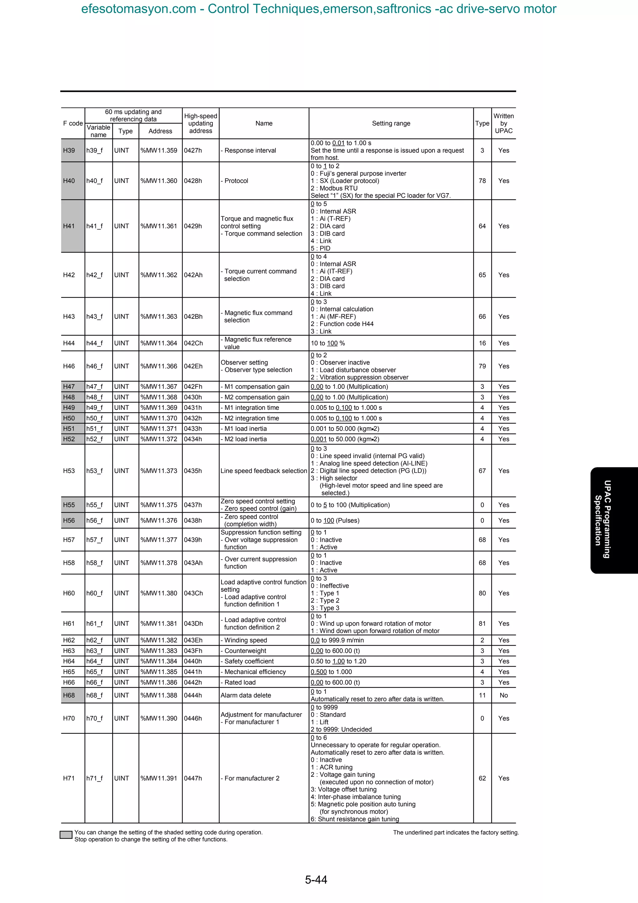
![5. UPAC Programming Specification
5-45
60 ms updating and
referencing data
F code
Variable
name
Type Address
High-speed
updating
address
Name Setting range Type
Written
by
UPAC
H72 h72_f UINT %MW11.392 0448h - For manufacturer 3
0 to 9999
0 : Standard
1 to 9999: Undecided
0 Yes
H73 h73_f UINT %MW11.393 0449h - For manufacturer 4
0 to 9999
0 : Standard
1 to 9999: Undecided
0 Yes
Table 5-2-43 A: Alternative Motor Parameters
60 ms updating and
referencing data
F code
Variable
name
Type Address
High-speed
updating
address
Name Setting range Type
Written
by
UPAC
A01 a01_f UINT %MW11.401 0501h
M2 motor parameter setting
- M2 control method
0 to 1
M2 is exclusively for vector control of induction motor.
0 : Vector control
1 : Sensorless vector control
55 Yes
A02 a02_f UINT %MW11.402 0502h - M2 rated capacity
When F60 = 0, 0.00 to 500.00kW
When F60 = 1, 0.00 to 600.00HP
3 Yes
A03 a03_f WORD %MW11.403 0503h - M2 rated current
0.01 to 99.99A
100.0 to 999.9A
1000 to 2000A
13 Yes
A04 a04_f UINT %MW11.404 0504h - M2 rated voltage 80 to 999 V 0 Yes
A05 a05_f UINT %MW11.405 0505h - M2 rated speed 50 to 1500 to 24000 r/min 0 Yes
A06 a06_f UINT %MW11.406 0506h - M2 maximum speed 50 to 1500 to 24000 r/min 0 Yes
A07 a07_f UINT %MW11.407 0507h - M2 poles 2 to 4 to 12 (Poles) 1 Yes
A08 a08_f UINT %MW11.408 0508h - M2-%R1 0.00 to 30.00 % 3 Yes
A09 a09_f UINT %MW11.409 0509h - M2-%X 0.00 to 50.00 % 3 Yes
A10 a10_f WORD %MW11.410 050Ah - M2 exciting current
0.01 to 99.99A
100.0 to 999.9A
1000 to 2000A
13 Yes
A11 a11_f WORD %MW11.411 050Bh - M2 torque current
0.01 to 99.99A
100.0 to 999.9A
1000 to 2000A
13 Yes
A12 a12_f UINT %MW11.412 050Ch - M2 slip (driving) 0.001 to 10.000 Hz 4 Yes
A13 a13_f UINT %MW11.413 050Dh - M2 slip (braking) 0.001 to 10.000 Hz 4 Yes
A14 a14_f UINT %MW11.414 050Eh - M2 iron loss coefficient 1 0.00 to 10.00 % 3 Yes
A15 a15_f UINT %MW11.415 050Fh - M2 iron loss coefficient 2 0.00 to 10.00 % 3 Yes
A16 a16_f UINT %MW11.416 0510h - M2 iron loss coefficient 3 0.00 to 10.00 % 3 Yes
A17 a17_f UINT %MW11.417 0511h
- M2 magnetic saturation
coefficient 1
0.0 to 100.0 % 2 Yes
A18 a18_f UINT %MW11.418 0512h
- M2 magnetic saturation
coefficient 2
0.0 to 100.0 % 2 Yes
A19 a19_f UINT %MW11.419 0513h
- M2 magnetic saturation
coefficient 3
0.0 to 100.0 % 2 Yes
A20 a20_f UINT %MW11.420 0514h
- M2 magnetic saturation
coefficient 4
0.0 to 100.0 % 2 Yes
A21 a21_f UINT %MW11.421 0515h
- M2 magnetic saturation
coefficient 5
0.0 to 100.0 % 2 Yes
A22 a22_f UINT %MW11.422 0516h - M2 secondary time constant 0.001 to 9.999 s 4 Yes
A23 a23_f UINT %MW11.423 0517h
- M2 induction voltage
coefficient
0 to 999 V 0 Yes
A24 a24_f UINT %MW11.424 0518h
- M2-R2 correction coefficient
1
0.000 to 5.000 4 Yes
A25 a25_f UINT %MW11.425 0519h
- M2-R2 correction coefficient
2
0.000 to 5.000 4 Yes
A26 a26_f UINT %MW11.426 051Ah
- M2-R2 correction coefficient
3
0.010 to 5.000 4 Yes
A27 a27_f UINT %MW11.427 051Bh
- M2 exciting current
correction coefficient
0.000 to 5.000 4 Yes
A28 a28_f UINT %MW11.428 051Ch - M2-ACR-P (gain) 0.1 to 1.0 to 20.0 2 Yes
A29 a29_f UINT %MW11.429 051Dh - M2-ACR-I (integration time) 0.5 to 1.0 to 100.0 ms 2 Yes
A30 a30_f UINT %MW11.430 051Eh M2-PG pulses 100 to 1024 to 60000 0 Yes
A31 a31_f UINT %MW11.431 051Fh M2 thermistor selection
0 to 1 to 3
0 : No thermistor
1 : NTC thermistor
2 : PTC thermistor
3 : Ai[M-TMP]
Set the protection level of the motor protection function
using E30 through E32.
84 Yes
A32 a32_f UINT %MW11.432 0520h
M2 electronic thermal
overload relay setting
- M2 electronic thermal
overload relay (function
selection)
0 to 2
Motor overheat protection function when special NTC
thermistor for VG motor is used. In this case, select
“inactive” for the setting of the electronic thermal
overload relay.
0 : Inactive (with special motor for VG)
1 : Active (for general purpose motors; use for internal
cooling fan.)
2 : Active (for inverter motors; use for external cooling
fan.)
85 Yes
A33 a33_f WORD %MW11.433 0521h
- M2 electronic thermal
overload relay
(operation level)
0.01 to 99.99A
100.0 to 999.9A
1000 to 2000A
13 Yes
You can change the setting of the shaded setting code during operation.
Stop operation to change the setting of the other functions.
The underlined part indicates the factory setting.
efesotomasyon.com - Control Techniques,emerson,saftronics -ac drive-servo motor](https://image.slidesharecdn.com/vg7upacmanual-140613044924-phpapp01/75/Vg7-upac-manual-249-2048.jpg)
![5-46
60 ms updating and
referencing data
F code
Variable
name
Type Address
High-speed
updating
address
Name Setting range Type
Written
by
UPAC
A34 a34_f UINT %MW11.434 0522h
- M2 electronic thermal
overload relay
(thermal time constant)
0.5 to 75.0 min 2 Yes
A35 a35_f UINT %MW11.435 0523h
Setting of motor parameter
M3 for V/f control
- M3 rated capacity
When F60 = 0, 0.00 to 500.00kW
When F60 = 1, 0.00 to 600.00HP
3 Yes
A36 a36_f WORD %MW11.436 0524h - M3 rated current
0.01 to 99.99A
100.0 to 999.9A
1000 to 2000A
13 Yes
A37 a37_f UINT %MW11.437 0525h - M3 rated voltage 80 to 999 V 0 Yes
A38 a38_f UINT %MW11.438 0526h
- M3 maximum output voltage
(at V/f maximum speed)
80 to 999 V 0 Yes
A39 a39_f UINT %MW11.439 0527h - M3 rated speed 50 to 1500 to 24000 r/min 0 Yes
A40 a40_f UINT %MW11.440 0528h - M3 maximum speed 50 to 1500 to 24000 r/min 0 Yes
A41 a41_f UINT %MW11.441 0529h - M3 poles 2 to 4 to 12 (Poles) 1 Yes
A42 a42_f UINT %MW11.442 052Ah - M3-%R1 0.00 to 30.00 % 3 Yes
A43 a43_f UINT %MW11.443 052Bh - M3-%X 0.00 to 50.00 % 3 Yes
A44 a44_f WORD %MW11.444 052Ch - M3 exciting current
0.01 to 99.99A
100.0 to 999.9A
1000 to 2000A
13 Yes
A45 a45_f INT %MW11.445 052Dh
- M3 slip compensation
variable
-20.000 to 0.000 to 5.000 Hz 8 Yes
A46 a46_f UINT %MW11.446 052Eh M3 torque boost
0.0 to 20.0
0.0: Automatic torque boost (for constant torque load)
0.1 to 0.9: For variable torque load
1.0 to 1.9: For proportional torque load
2.0 to 20.0: For constant torque load
2 Yes
A47 a47_f UINT %MW11.447 052Fh M3 thermistor selection
0 to 1 to 3
0 : No thermistor
1 : NTC thermistor
2 : PTC thermistor
3 : Ai[M-TMP]
Set the protection level of the motor protection function
at E30 through E32.
84 Yes
A48 a48_f UINT %MW11.448 0530h
M3 electronic thermal
overload relay setting
- M3 electronic thermal
overload relay
(function selection)
0 to 2
0 : Inactive (select when PTC thermistor is used.)
1 : Active (for general purpose motors; use for internal
cooling fan.)
2 : Active
(for inverter motors; use for external cooling fan.)
85 Yes
A49 a49_f WORD %MW11.449 0531h
- M3 electronic thermal
overload relay
(operation level)
0.01 to 99.99A
100.0 to 999.9A
1000 to 2000A
13 Yes
A50 a50_f UINT %MW11.450 0532h
- M3 electronic thermal
overload relay
(thermal time constant)
0.5 to 75.0 min 2 Yes
Table 5-2-44 O: Optional Functions
60 ms updating and
referencing data
F code
Variable
name
Type Address
High-speed
updating
address
Name Setting range Type
Written
by
UPAC
o01 o01_f UINT %MW11.465 0601h
DIA, DIB option setting
- DIA function selection
0 to 1
0 : Binary
1 : BCD
86 Yes
o02 o02_f UINT %MW11.466 0602h - DIB function selection
0 to 1
0 : Binary
1 : BCD
86 Yes
o03 o03_f UINT %MW11.467 0603h - DIA BCD input setting 99 to 1000 to 7999 0 Yes
o04 o04_f UINT %MW11.468 0604h - DIB BCD input setting 99 to 1000 to 7999 0 Yes
o05 o05_f UINT %MW11.469 0605h
PG (PD) option setting
- Feedback pulse selection
0 to 1
0 : PG built in main body
1 : PG (PD) option
96 Yes
o06 o06_f UINT %MW11.470 0606h
PG (LD) option setting
- Digital line speed detection
definition (encoder pulses)
100 to 1024 to 60000 (P/R) 0 Yes
o07 o07_f UINT %MW11.471 0607h
- Digital line speed detection
definition
(detection pulse correction 1)
1 to 1000 to 9999 0 Yes
o08 o08_f UINT %MW11.472 0608h
- Digital line speed detection
definition
(detection pulse correction 2)
1 to 1000 to 9999 0 Yes
o09 o09_f UINT %MW11.473 0609h
PMPG option setting
- ABS signal input definition
(synchronous)
0 to 16 0 Yes
o10 o10_f WORD %MW11.474 060Ah
- Magnetic pole position offset
(synchronous)
0000 to FFFF 9 Yes
o11 o11_f UINT %MW11.475 060Bh
- Salient pole ratio
(%Xq/%Xd)
1.000 to 3.000 4 Yes
o12 o12_f UINT %MW11.476 060Ch
PG (PR) pulse string option
setting
- Command pulse selection
0 to 1
0: PG (PR) option
1: Internal speed command
97 Yes
You can change the setting of the shaded setting code during operation.
Stop operation to change the setting of the other functions.
The underlined part indicates the factory setting.
efesotomasyon.com - Control Techniques,emerson,saftronics -ac drive-servo motor](https://image.slidesharecdn.com/vg7upacmanual-140613044924-phpapp01/75/Vg7-upac-manual-250-2048.jpg)
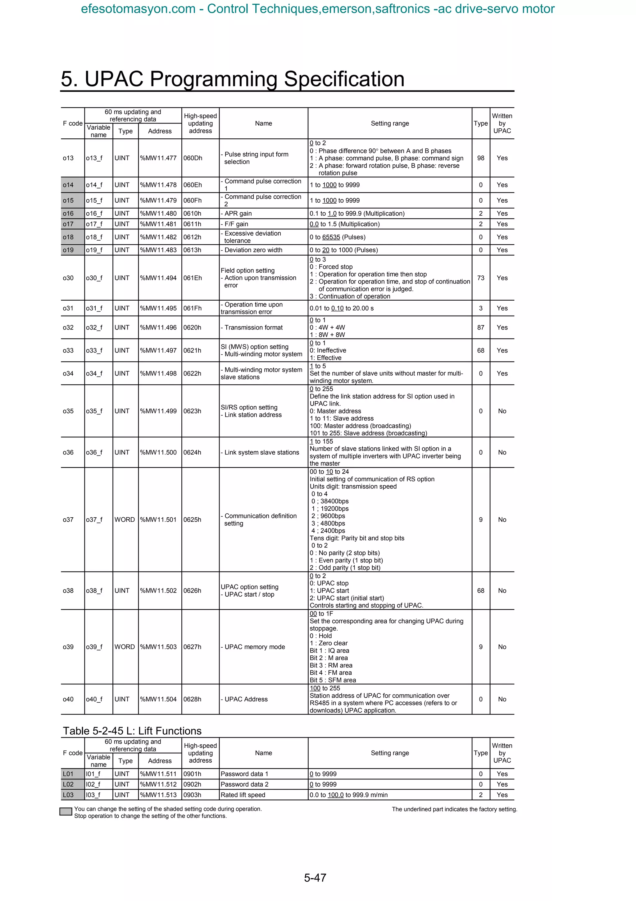
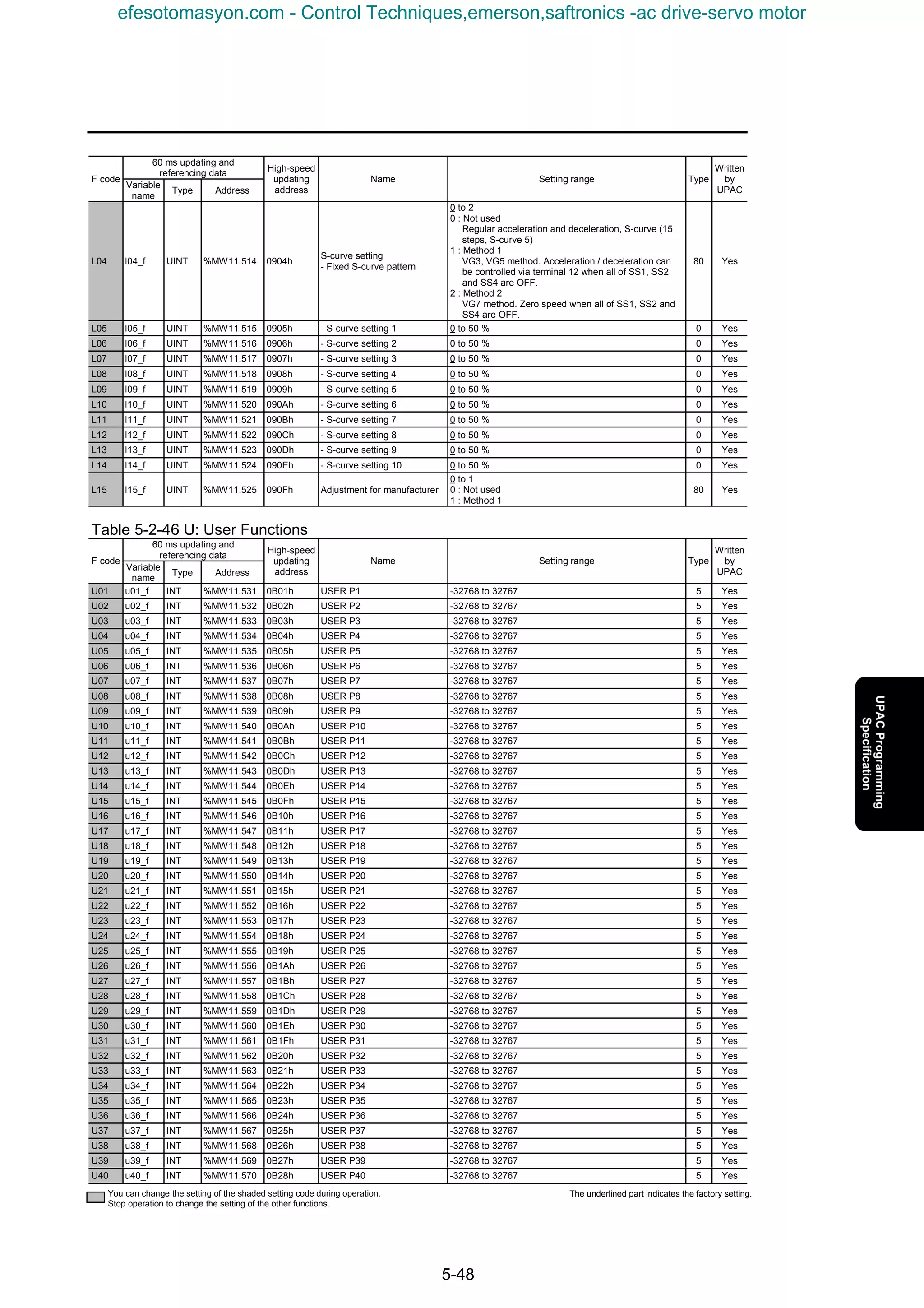
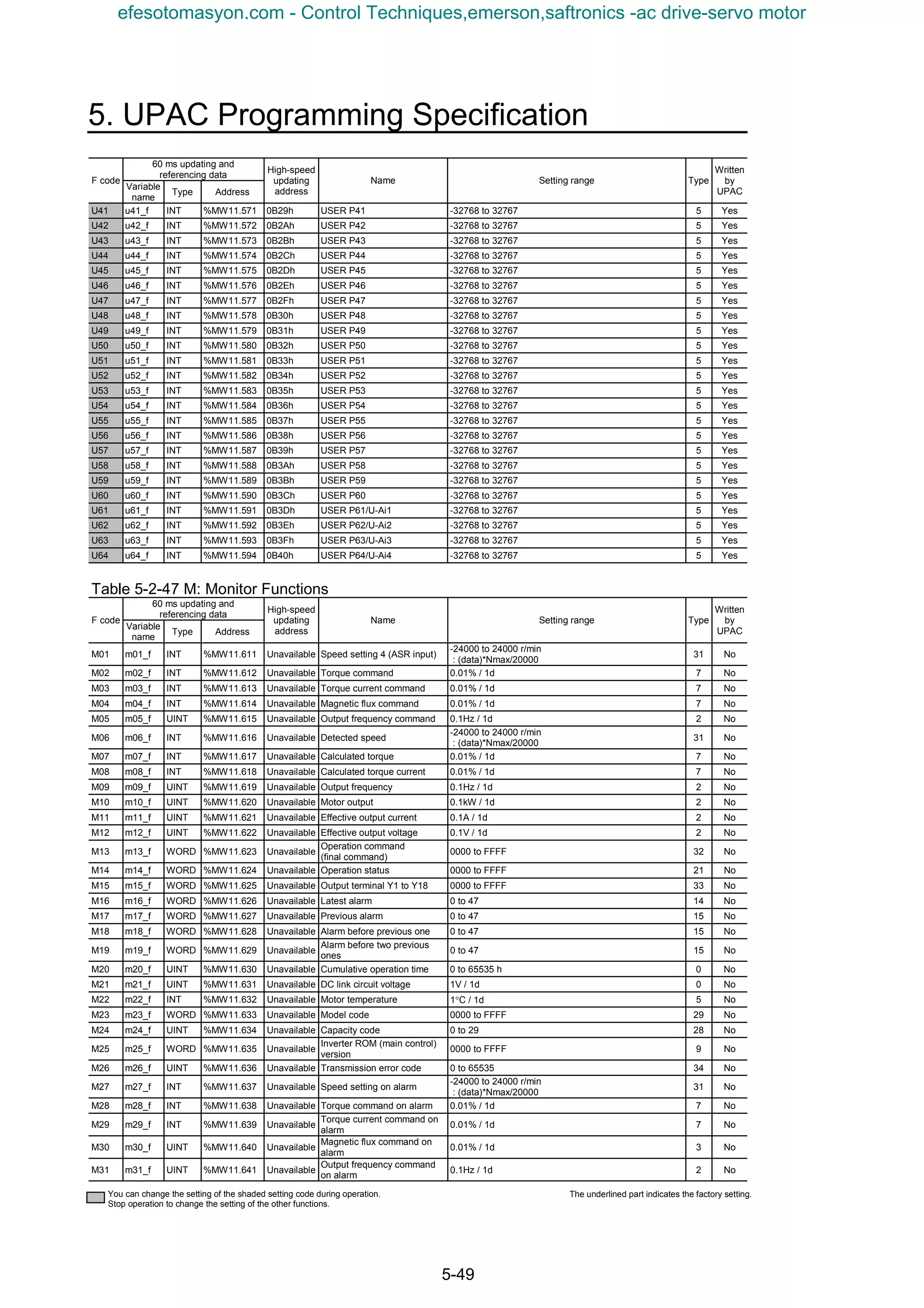
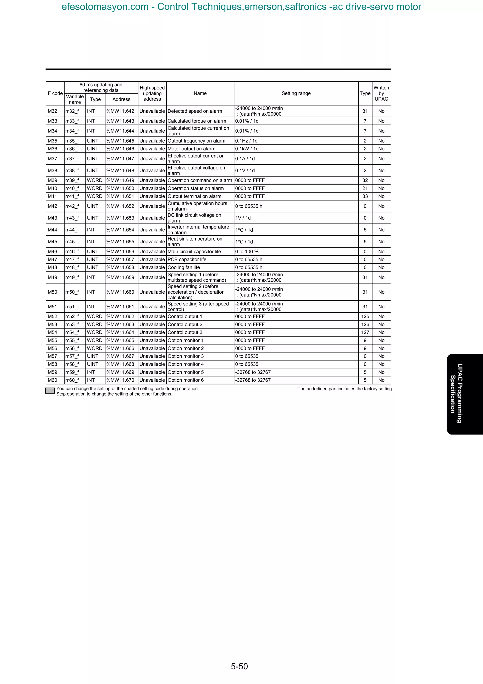
![5. UPAC Programming Specification
5-51
5.2.3.4 Data format list
Execution by code.
Table 5-2-48
Code Description Display/setting Resolution Notes
0 Integer 0, 1, 2, 3, ⋅⋅⋅⋅⋅⋅ 1
1 Integer 0, 2, 4, 6, ⋅⋅⋅⋅⋅⋅ 2 Only for pole number of motor
2 0.0, 0.1, 0.2, ⋅⋅⋅⋅⋅⋅ 0.1
3 0.00, 0.01, 0.02, ⋅⋅⋅⋅⋅⋅ 0.01
4
Fixed point
0.001, 0.002, 0.003, ⋅⋅⋅⋅⋅⋅ 0.001
5 Integer (signed) -2, -1, 0, 1, 2, ⋅⋅⋅⋅⋅⋅ 1
6 -0.1, 0.0, 0.1, ⋅⋅⋅⋅⋅⋅ 0.1
7 -0.01, 0.00, 0,01, ⋅⋅⋅⋅⋅⋅ 0.01
8
Fixed point (signed)
-0.001, 0.000, 0.001, ⋅⋅⋅⋅⋅⋅ 0.001
9 Hexadecimal 1A8E 1h
Initial cursor position is left end.
Cursor does not move automatically.
When setting range is from 00 to 11,
you should specify individual digits to
set only 00, 01, 10, or 11.
10 Special data 3 0.75, 1, 2, ⋅⋅⋅⋅⋅⋅ 14, 15 Carrier frequency setting
11 Operation data 1 Reset to 0 after writing
The following data have special formats.
Type [12]: Time, current, power, PID process values
15 14 11 9 0
Type [13]: Current and others
15 13 0
Mantissa ⋅⋅⋅⋅⋅⋅⋅⋅⋅⋅⋅⋅⋅⋅⋅⋅ Exponent=0: 0 to 999, Exponent=1
to 3: 100 to 999
Exponent⋅⋅⋅⋅⋅⋅⋅⋅⋅⋅⋅⋅⋅⋅⋅⋅ 0: 0.01 times (0.00 to 9.99)
1: 0.1 times (10.0 to 99.9)
2: 1 times (100 to 999)
3: 10 times (1,000 to 9,990)
Polarity⋅⋅⋅⋅⋅⋅⋅⋅⋅⋅⋅⋅⋅⋅⋅⋅⋅⋅⋅⋅ 0: Positive (+), 1: Negative (−)
Mantissa ⋅⋅⋅⋅⋅⋅⋅⋅⋅⋅⋅⋅⋅⋅⋅ Exponent=0: 0 to 9999, Exponent=1
to 3: 1,000 to 9,999
Exponent⋅⋅⋅⋅⋅⋅⋅⋅⋅⋅⋅⋅⋅⋅⋅ 0: 0.01 times (0.00 to 99.99)
1: 0.1 times (100.0 to 999.9)
2: 1 times (1,000 to 9,999)
3: 10 times (10,000 to 99,990)
efesotomasyon.com - Control Techniques,emerson,saftronics -ac drive-servo motor](https://image.slidesharecdn.com/vg7upacmanual-140613044924-phpapp01/75/Vg7-upac-manual-255-2048.jpg)
![5-52
Type [14]: Cause of alarm
15 12 8 7 0
Table 5-2-49 Alarm codes
Code Display Description Code Display Description Code Display Description
0 --- No alarm 17 Lin Input phase loss 34 Ar1
Error code 1 for specific
user application
1 IPE IPM error 18 LU Undervoltage 35 Ar2
Error code 2 for specific
user application
2 dbH DB resistor overheating 19 nrb
NTC thermistor
disconnection
36 Ar3
Error code 3 for specific
user application
3 dCF DC fuse blown 20 OC Overcurrent 37 Ar4
Error code 4 for specific
user application
4 dO
Excessive position
deviation
21 OH1 Overheating at heat sink 38 Ar5
Error code 5 for specific
user application
5 EF Ground fault 22 OH2 External alarm 39 Ar6
Error code 6 for specific
user application
6 Er1 Memory error 23 OH3 Inverter internal overheat 40 Ar7
Error code 7 for specific
user application
7 Er2
KEYPAD panel
communication error
24 OH4 Motor overheat 41 Ar8
Error code 8 for specific
user application
8 Er3 CPU error 25 OL1 Motor 1 overload 42 Ar9
Error code 9 for specific
user application
9 Er4 Network error 26 OL2 Motor 2 overload 43 ArA
Error code A for specific
user application
10 Er5
RS485 communication
error
27 OL3 Motor 3 overload 44 ArB
Error code B for specific
user application
11 Er6
Operation procedure
error
28 OLU Inverter unit overload 45 ArC
Error code C for specific
user application
12 Er7 Output wiring error 29 OS Overspeed 46 ArD
Error code D for specific
user application
13 Er8 A/D converter error 30 OU Overvoltage 47 ArE
Error code E for specific
user application
14 Er9 Speed disagreement 31 PbF Charging circuit error 48 ArF
Error code F for specific
user application
15 ErA UPAC error 32 P9 PG error
16 Erb
Inter-inverter
communication error
33 Ar0
Error code 0 for specific
user application
Type [15]: Alarm history
15 8 7 0
Type [16]: Percentage
15 8 7 0
Alarm code⋅⋅⋅⋅⋅⋅⋅⋅⋅⋅⋅⋅⋅⋅⋅⋅⋅⋅⋅⋅⋅⋅⋅⋅⋅⋅⋅⋅⋅⋅⋅⋅⋅⋅⋅⋅⋅⋅⋅⋅0 to 48
Order of alarm occurrence ⋅⋅⋅⋅⋅⋅⋅⋅⋅⋅⋅⋅1st to 5th
Number of alarms⋅⋅⋅⋅⋅⋅⋅⋅⋅⋅⋅⋅⋅⋅⋅⋅⋅⋅⋅⋅⋅⋅⋅⋅⋅⋅⋅⋅1 to 5
Alarm code⋅⋅⋅⋅⋅⋅⋅⋅⋅⋅⋅⋅⋅⋅⋅⋅⋅⋅⋅⋅⋅⋅⋅⋅⋅⋅⋅⋅0 to 32 (See "Type [14]")
Number of the occurrence of the same alarm
⋅⋅⋅⋅⋅⋅⋅⋅⋅⋅⋅⋅⋅⋅⋅⋅0 to 255
Percentage⋅⋅⋅⋅⋅⋅⋅⋅⋅−300% to 300% (−30,000 to 30,000)
Decimal places are not displayed.
efesotomasyon.com - Control Techniques,emerson,saftronics -ac drive-servo motor](https://image.slidesharecdn.com/vg7upacmanual-140613044924-phpapp01/75/Vg7-upac-manual-256-2048.jpg)
![5. UPAC Programming Specification
5-53
Type [21]: Operation status
15 8 7 0
Type [26]: DIOB option input state
Type [27]: DIOB option output state
15 8 7 0
0) FWD (forward operation)
1) REV (reverse operation)
2) EXT (DC braking, pre-exciting)
3) INT (Inverter shut off)
4) BRK (Braking)
5) NUV (DC link circuit voltage established)
6) TL (Torque limiting)
7) VL (Voltage limiting)
8) IL (Current limiting)
9) ACC (Accelerating)
10) DEC (Decelerating)
11) ALM (Alarm relay output)
12) 0: REM/LOC, 1: COM
13) 0: KEYPAD panel, 1: RS485, 2: link option
14) Not used
15) Writing⋅⋅⋅⋅⋅⋅⋅⋅0: OFF, 1: ON
0: OFF
1: ON
[26] Input state [27] Output state
0) X21, Y21
1) X22, Y22
2) X23, Y23
3) X24, Y24
4) X25, Y25
5) X26, Y26
6) X27, Y27
7) X28, Y28
8) X29, Y29
9) X30, Y30
10) X31
11) X32
12) X33
13) X34
14) X35
15)・・・・・・・・・・・・・・X36
0;OFF, 1;ON
efesotomasyon.com - Control Techniques,emerson,saftronics -ac drive-servo motor](https://image.slidesharecdn.com/vg7upacmanual-140613044924-phpapp01/75/Vg7-upac-manual-257-2048.jpg)
![5-54
Type [28]: Inverter capacity
Table 5-2-50
Code
Inverter
capacity
Code
Inverter
capacity
Code
Inverter
capacity
Code
Inverter
capacity
0 0.05 8 5.5 16 45 24 220
1 0.1 9 7.5 17 55 25 250
2 0.2 10 11 18 75 26 280
3 0.4 11 15 19 90 27 315
4 0.75 12 18.5 20 110 28 355
5 1.5 13 22 21 132 29 400
6 2.2 14 30 22 160
7 3.7 15 37 23 200
Type [29]: Inverter model (common to entire FUJI inverter system)
The number is fixed to 1213h or 1214h for the VG inverters.
200V system: fixed to 1213h
400V system: fixed to 1214h
Table 5-2-51
Type [31]: Speed
15 8 7 0
Data (0 to ±20,000) → (0 to ±12,000 × r/min) : (Data) × Nmax/20,000 conversion
(Example) When the maximum speed is Nmax=1,500r/min,
• If you want to direct a speed reference of 1,000r/min,
Specify a data of × 20,000 → 13,333.
• If the read out data is 3,500,
You can determine the speed is × 3,500 → 262.5r/min.
Type [32]: Operation commands, [33]: Y1 to Y18
This type is the same as S06 and S07.
15 8 7 0
1,000
1,500
1,500
20,000
[32] [33]
0) FWD (forward operation command) Y1
1) REV (reverse operation command) Y2
2) X1 Y3
3) X2 Y4
4) X3 RY
5) X4 Not used
6) X5 Not used
7) X6 Not used
8) X7 Y11
9) X8 Y12
10) X9 Y13
11) X11 Y14
12) X12 Y15
13) X13 Y16
14) X14 Y17
15) RST (RESET command) Y18
0: OFF
1: ON
Model Development code Series Voltage
Code
Division Display Division Display Division Display Division Display
0 - - - -
1 VG VG 11 series 11
Standard for
domestic
Single-phase
100V
6
2 G G 7 series 7
Standard for
Asia
Single-phase
200V
7
3 P P
Standard for
China
Three-phase
200V
2
4 E E
Standard for
Europe
Three-phase
400V
4
5 C C
Standard for
USA
Three-phase
575V
5
6 S S
efesotomasyon.com - Control Techniques,emerson,saftronics -ac drive-servo motor](https://image.slidesharecdn.com/vg7upacmanual-140613044924-phpapp01/75/Vg7-upac-manual-258-2048.jpg)
![5. UPAC Programming Specification
5-55
Type [34]: Communication error codes
15 8 7 0
Description of alarms in the communication through the link (RS485, T-Link, field bus). The
following data is set to the monitor data M26 according to the communication status. The codes
listed in the column "KEYPAD panel display" is displayed on the KEYPAD panel as a
communication error .
Table 5-2-52
Code
KEYPAD panel
display
Communication error name Description
0 - No communication error 1 Normal communication
2 A data is written to an unused address of the function code (writing
to address out of the specified range is defined separately).
3 A data is read from an unused address. The data will be "0000".
4 Writing to the S area while link operation is disabled. The data will
not be reflected and cause no error.
5 A data out of range is written to the S area. The data is written after
adjusted to the upper or the lower limit.
6 Access from another link or the KEYPAD panel occurs during data
writing (EEPROM other than the S area is accessed).
7 Writing to operation data (such as tuning or initialization) during
multiple function codes are being written once through the link. The
inverter decides that the procedure is canceled and continues the
writing.
8 Writing to/reading from option function codes that are not displayed
on the KEYPAD panel.
1 to 32 - Alarm codes specific to the
VG7S
Alarm codes specific to models other than communication errors.
33 to 70 - Not used
71 - Checksum error, CRC error Software error Checksum value or CRC value does not
match.
72 - Parity error Hardware error Parity does not match.
73 - Others (such as overrun,
framing)
Physical (reception) errors other than above.
74 01 Format error Incorrect format.
Characters requesting transmission are incorrect. Characters
terminating transmission are not in the specified order.
75 01 Command error Codes other than the specified commands are transmitted.
76 07 Link priority error 1 Writing to the S area through RS485 while a link option is installed.
2 Writing to the S area through a link with lower priority while multiple
link options are installed.
77 07 No right to write function
code data
Not used for VG7S
78 02 Function code error 1 Access to a data out of the address range of the function codes
(such as access to a data over F80).
2 Writing data over 16 words.
79 07 Error on writing to write-
disabled data
1 Write-disabled function codes (Read-only data or the M area).
2 Function codes write-disabled during operation.
3 Writing through the link to data out of the S area in "write-disabled
through link" mode. Note that F00 or "Write enable for KEYPAD"
cannot protect from writing through the link.
4 Function codes that cannot be written through the link (link function
codes: H31 to 40, o5x, o6x, and o8x).
5 Writing to M1 function code (P) area when motor parameters are
protected.
6 Writing through the link in the copy mode operation of the KEYPAD
panel.
80 03 Data error Written data is out of the setting range in the area other than the S
area.
81 07 Error during writing Another writing request comes from the same source while writing
function code data (EEPROM other than the S area is accessed).
Note: The alarm codes 1 to 32 constitute a code system specific to the VG7S different from the assignment for the general-
purpose inverters.
The communication error codes 71 to 81 are common to the different models. Note that some causes of alarm are
specific to models.
The KEYPAD panel does not display raw communication error codes but the values in the "KEYPAD panel display"
column in the table above.
The KEYPAD panel displays "∗∗" when it receives data that does not have a corresponding "KEYPAD panel display"
in the table above.
efesotomasyon.com - Control Techniques,emerson,saftronics -ac drive-servo motor](https://image.slidesharecdn.com/vg7upacmanual-140613044924-phpapp01/75/Vg7-upac-manual-259-2048.jpg)
![5-56
Type [35]: X function normally open/closed
Type [36]: Y function normally open/closed
15 8 7 0
Type [40] to [99]
These types are reserved for the manufacturer. Users can considers these types as type [0] to use.
Type [125]: Control output 1
15 8 7 0
X function Y function
0) X1 Y1
1) X2 Y2
2) X3 Y3
3) X4 Y4
4) X5 Y5
5) X6
6) X7
7) X8
8) X9
0: Normally open
1: Normally closed
0) Inverter running [RUN]
1) Speed existence [N-EX]
2) Speed agreement [N-AG]
3) Speed equivalence [N-AR]
4) Detected speed 1 [N-DT1]
5) Detected speed 2 [N-DT2]
6) Detected speed 3 [N-DT3]
7) Stopping on undervoltage [LU]
8) Detected torque polarity (braking/driving)[B/D]
9) Torque limiting [TL]
10) Detected torque 1 [T-DT1]
11) Detected torque 2 [T-DT2]
12) KEYPAD operation mode [KP]
13) Inverter stoppage [STOP]
14) Operation ready output [RDY]
15) Magnetic-flux detection signal [MF-DT]
efesotomasyon.com - Control Techniques,emerson,saftronics -ac drive-servo motor](https://image.slidesharecdn.com/vg7upacmanual-140613044924-phpapp01/75/Vg7-upac-manual-260-2048.jpg)
![5. UPAC Programming Specification
5-57
Type [126]: Control output 2
15 8 7 0
Type [127]: Control output 3
15 8 7 0
0) Motor M2 selection status [SW-M2]
1) Motor M3 selection status [SW-M3]
2) Brake release signal [BRK]
3) Alarm indication [AL1]
4) Alarm indication [AL2]
5) Alarm indication [AL4]
6) Alarm indication [AL8]
7) Fan operation signal [FAN]
8) Auto-resetting [TRY]
9) Universal DO [U-DO]
10) Heat sink overheat early warning [INV-OH]
11) Synchronization completion signal[SY-C]
12) Lifetime alarm [LIFE]
13) Under accelerating [U-ACC]
14) Under decelerating [U-DEC]
15) Inverter overload early warning [INV-OL]
0) Motor temperature early warning [M-OH]
1) Motor overload early warning [M-OL]
2) DB overload early warning [DB-OL]
3) Link transmission error [LK-ERR]
4) Load adaptive control under limiting [ANL]
5) Load adaptive control under calculation[ANC]
6) Analog torque bias hold [TBH]
7) Optional Do 1 [O-DI1]
8) Optional Do 2 [O-DI2]
9) Optional Do 3 [O-DI3]
10) Optional Do 4 [O-DI4]
11) Optional Do 5 [O-DI5]
12) Optional Do 6 [O-DI6]
13) Optional Do 7 [O-DI7]
14) Optional Do 8 [O-DI8]
15) Optional Do 9 [O-DI9]
efesotomasyon.com - Control Techniques,emerson,saftronics -ac drive-servo motor](https://image.slidesharecdn.com/vg7upacmanual-140613044924-phpapp01/75/Vg7-upac-manual-261-2048.jpg)


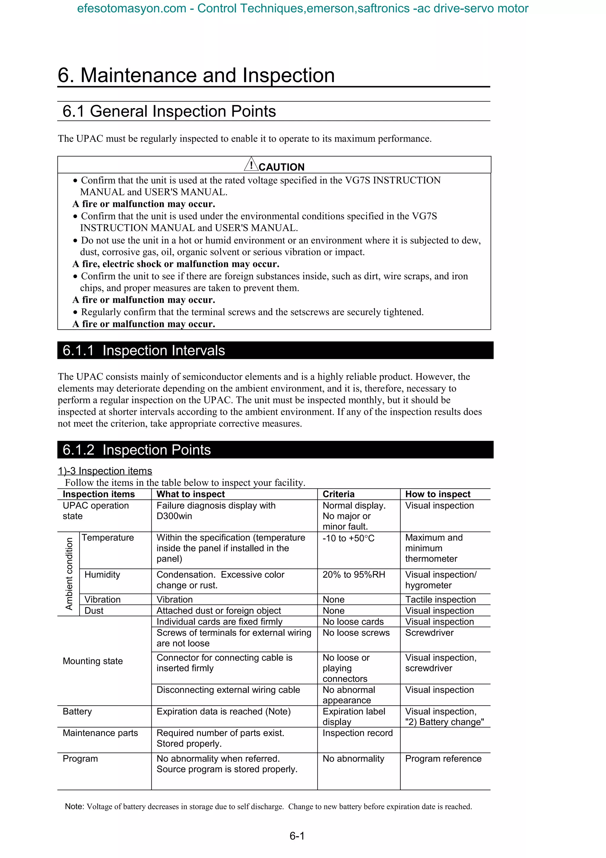
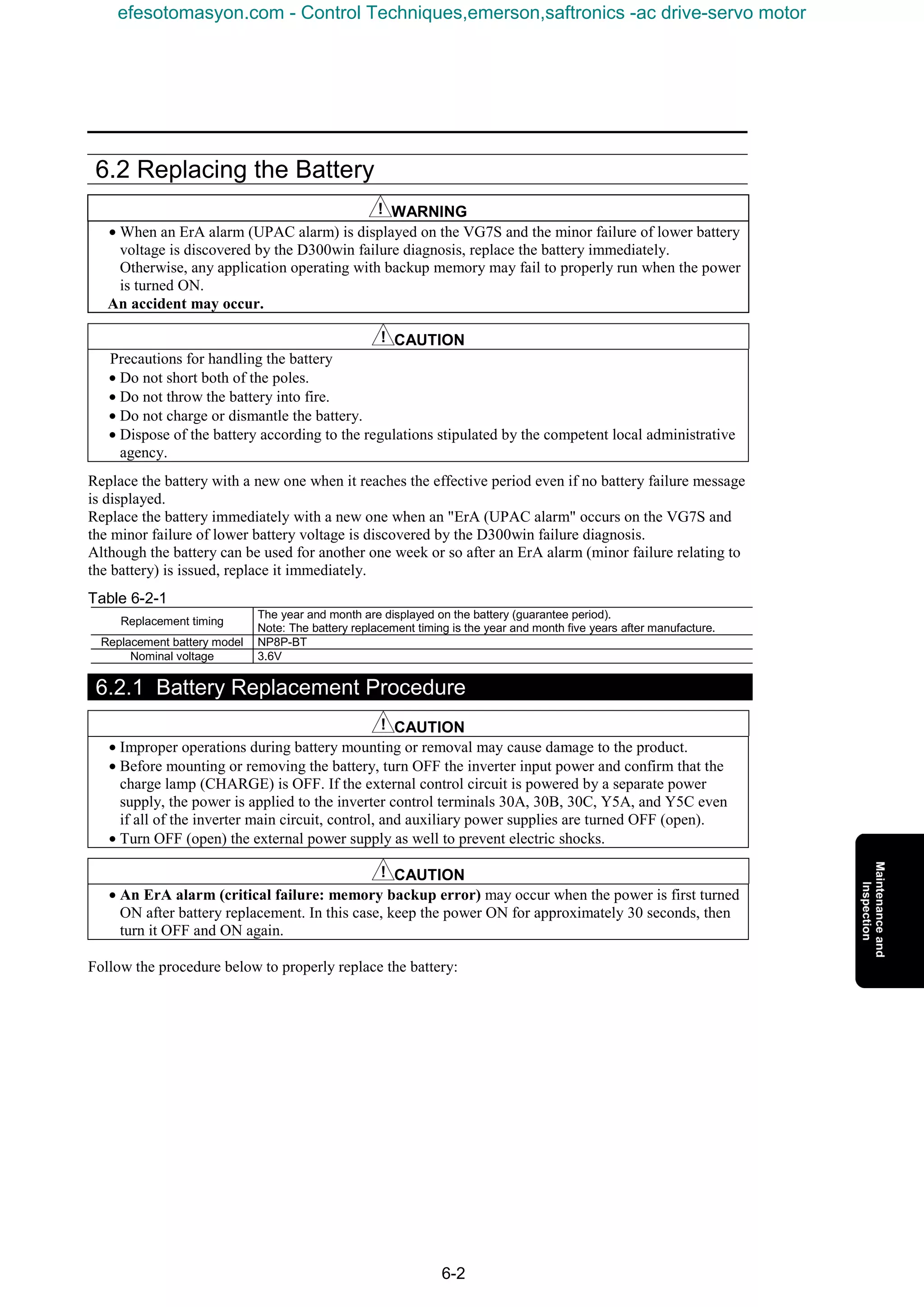


The document provides safety precautions and instructions for operating an inverter. It describes potential hazards such as electric shock, fire, and injury that could occur from improper operation or maintenance. Specific warnings are given for instructions on use, installation, wiring, operation, maintenance, inspection, replacement, and disposal. Operators and maintenance personnel are instructed to read the manual carefully before handling the device to ensure safe use.


![Ct2000 es manual_english_version_1[1].0](https://cdn.slidesharecdn.com/ss_thumbnails/ct2000esmanualenglishversion11-140613213448-phpapp01-thumbnail.jpg?width=640&height=640&fit=bounds)


![Ct2000 pro plus_manual_english[1]](https://cdn.slidesharecdn.com/ss_thumbnails/ct2000proplusmanualenglish1-140613213527-phpapp02-thumbnail.jpg?width=640&height=640&fit=bounds)


