Downloaded 20 times

![General Information
The manufacturer accepts no liability for any consequences resulting from inappropriate, negligent or incorrect
installation or adjustment of the optional operating parameters of the equipment or from mismatching the variable speed
drive with the motor.
The contents of this guide are believed to be correct at the time of printing. In the interests of a commitment to a policy
of continuous development and improvement, the manufacturer reserves the right to change the specification of the
product or its performance, or the contents of the guide, without notice.
All rights reserved. No parts of this guide may be reproduced or transmitted in any form or by any means, electrical or
mechanical including photocopying, recording or by an information storage or retrieval system, without permission in
writing from the publisher.
Drive software version
The software version of the drive can be checked by looking at Pr 11.29 (or Pr 0.50) and Pr 11.34. The software version
takes the form of zz.yy.xx, where Pr 11.29 displays zz.yy and Pr 11.34 displays xx, i.e. for software version 01.01.00,
Pr 11.29 would display 1.01 and Pr 11.34 would display 0.
If there is any doubt, contact a Control Techniques Drive Centre.
SM-ELV software version
The software version and identity number for the SM-ELV option module can be viewed in Pr 0.28 [1] (Pr 20.01) software
version and Pr 0.29 [1] (Pr 20.02) software identity number.
If there is any doubt, contact a Control Techniques Drive Centre.
Environmental statement
Control Techniques is committed to minimising the environmental impacts of its manufacturing operations and of its
products throughout their life cycle. To this end, we operate an Environmental Management System (EMS) which is
certified to the International Standard ISO 14001. Further information on the EMS, our Environmental Policy and other
relevant information is available on request, or can be found at www.greendrives.com.
The electronic variable-speed drives manufactured by Control Techniques have the potential to save energy and
(through increased machine/process efficiency) reduce raw material consumption and scrap throughout their long
working lifetime. In typical applications, these positive environmental effects far outweigh the negative impacts of product
manufacture and end-of-life disposal.
Nevertheless, when the products eventually reach the end of their useful life, they can very easily be dismantled into their
major component parts for efficient recycling. Many parts snap together and can be separated without the use of tools,
while other parts are secured with conventional screws. Virtually all parts of the product are suitable for recycling.
Product packaging is of good quality and can be re-used. Large products are packed in wooden crates, while smaller
products come in strong cardboard cartons which themselves have a high recycled fibre content. If not re-used, these
containers can be recycled. Polythene, used on the protective film and bags for wrapping product, can be recycled in the
same way. Control Techniques' packaging strategy favours easily-recyclable materials of low environmental impact, and
regular reviews identify opportunities for improvement.
When preparing to recycle or dispose of any product or packaging, please observe local legislation and best practice.
Copyright © August 2006 Control Techniques Drives Limited
Issue Number: 1](https://image.slidesharecdn.com/unispelevator-140613204659-phpapp02/85/Uni-sp-elevator-2-320.jpg)
![Safety
Information
General Installation
Lift software
functions
I/O
configuration
Basic
operation
Parameters Set-up Optimisation
Rescue
operation
SMARTCARD
operation
Commissioning
software tools
Diagnostics
Unidrive SP Elevator User Guide 13
Issue Number: 1 www.controltechniques.com
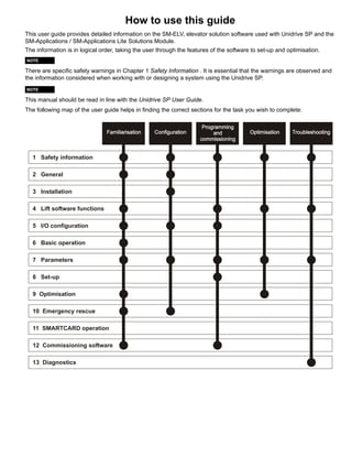
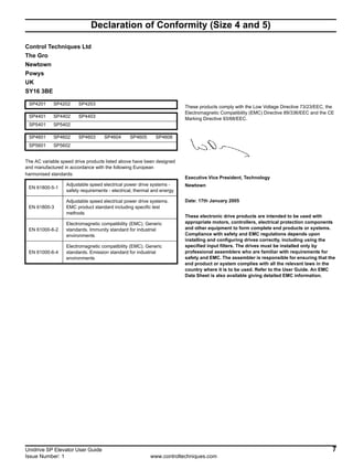
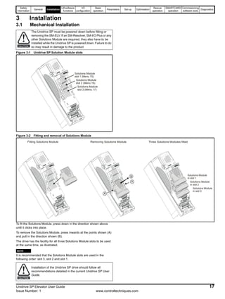
2 General
The Unidrive SP is a high performance drive making it an excellent choice for elevator applications. Figure 2-1 following shows the Unidrive SP
incorporated into an elevator system using the SM-ELV and where required an SM-I/O Plus can also be added to increase the drive’s I/O capability. In
addition other Solutions Modules can be fitted to further increase the Unidrive SP capability (e.g. SM-Resolver etc.).
Figure 2-1 Elevator system
2.1 Elevator system - Unidrive SP and
elevator controller
The Unidrive SP elevator solution (SM-ELV) software incorporates a
travel profile calculator and special operating level designed for
elevators. This software has additional features allowing it to be used for
both geared and gearless elevators.
The elevator software is introduced through either the SM-Applications
or SM-Applications Lite Solutions Module and special software.
The SM-Applications would be used where additional features are
required, e.g. larger DPL programs, extended user memory, RS485, CT-
Net or extended I/O.
The Unidrive SP elevator drive is controlled by a digital interface from
the elevator controller as shown in Figure 2-1. The elevator controller
software interprets the calls and produces the speed and direction
signals for the Unidrive SP.
The elevator controller provides all the safety related functions in this
system configuration, including the optional brake control in place of the
Unidrive SP.
2.2 SM-ELV operating mode
The Unidrive SP plus SM-ELV software creates a velocity motion profile,
which includes elevator application specific functions. It can be used for
both geared and gearless elevators operating in either Open Loop,
Closed Loop Vector or Servo mode. Brushless synchronous motors with
encoders (Incremental or Absolute) / resolvers and induction motors with
or without encoders (Incremental or Absolute) / resolvers can be
controlled.
The following operating modes can be selected through the SM-ELV
elevator software installed in the SM-Applications or SM-Applications Lite:
1. Pr 0.16[3] (Pr 20.13) = 0 Direct-to-floor positioning disabled
(Creep-to-floor active)
ELEVATOR
SHAFT
ABSOLUTE
ENCODER
SHAFT
POSITION
CALLS
SERVO
MOTOR
INDUCTION
MOTOR
SPEED FEEDBACK
WITH OR WITHOUT
SPEED FEEDBACK
BRAKE
CONTROL
CONTROL
CAR
COUNTER
BALANCE
INTERFACE
Digital Inputs / Outputs
Analogue Inputs / Outputs
Relays
Additional I/O
Digital Interface
Speed Selection
Speed monitoring
Brake Control
Car calls
Landing calls
Door control
Safety Related Functions
Elevator Controller
Open Loop
Closed Loop Vector
Servo
SM-Resolver
FeedbackSM-ELV Elevator Solution
Brake Control
Motor contactor control
Pre Door opening
SM-ELV Profile+Control
Open Loop
Closed Loop Vector
Servo
ELEVATOR
CONTROLLER](https://image.slidesharecdn.com/unispelevator-140613204659-phpapp02/85/Uni-sp-elevator-13-320.jpg)
![Safety
Information
General Installation
Lift software
functions
I/O
configuration
Basic
operation
Parameters Set-up Optimisation
Rescue
operation
SMARTCARD
operation
Commissioning
software tools
Diagnostics
14 Unidrive SP Elevator User Guide
www.controltechniques.com Issue Number: 1
2. Pr 0.16[3] (Pr 20.13) = 1 Direct-to-floor positioning with Stop signal
via analogue input 1 (T.5)
3. Pr 0.16[3] (Pr 20.13) = 2 Direct-to-floor positioning with Stop signal
via analogue input 2 (T.7)
4. Pr 0.16[3] (Pr 20.13) = 3 Direct-to-floor positioning with Stop signal
via analogue input 3 (T. 8)
5. Pr 0.16[3] (Pr 20.13) = 4 Direct-to-floor positioning with disable the
speed signals (controlling)
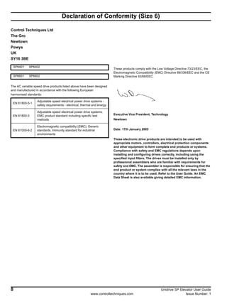
2.3 Features
The following Elevator functions are provided within the SM-ELV (SM-
Applications, SM-Applications Lite and Elevator software). The SM-ELV
software provides positioning controls associated with elevators e.g.
creep-to-floor and direct-to-floor with complete positioning control,
multiple speed selection and brake control as listed in Table 2-1.
The external lift controller evaluates the elevator signals and elevator
calls, and from these generates travel commands to the Unidrive SP.
The SM-ELV generates and modifies the required profile for travel.
N
A number of settings are necessary in order to use this software. To
simplify this a default feature is included which allows standard settings
for the initial run. (Refer to Pr 18.50 Default settings.)
N
Positioning with creep-to-floor is used in most applications. Therefore
creep-to-floor has been selected as the default setting for the elevator
software Pr 0.16[3] (Pr 20.13) = 0. N
Direct-to-floor positioning mode is enabled through Pr 0.16[3] (Pr 20.13)
as detailed in section 2.2 SM-ELV operating mode on page 13.
N
The external lift controller handles all the specific functions related to the
safety aspects of the elevator.
To assist with the set-up and commissioning of the elevator there are
also various commissioning software tools as detailed :
1. CT Soft - Allows parameter adjustment and upload / download
features.
2. CT Scope - Allows speed / current profiles to be monitored during
operation. Waveforms can be saved to file.
3. Lift - SP is designed specifically for lifts with various set-up features,
parameter adjustment upload / download, commissioning screens,
and oscilloscope features.
For more detailed information refer to Chapter 12 Commissioning
software tools .
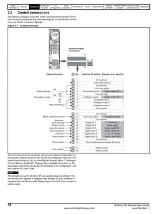
Table 2-1 Features
NOTE
NOTE
NOTE
Elevator software features Advantages
Text display with elevator terms Commissioning without User Guide is possible
Dedicated Unidrive Menu 0 Simplified operation with reduced parameter sets
Conventional data input units (mm/s, mm/s2
,) No calculation required to set-up the elevator drive
10 speed binary selections
Flexible interface, with range of speed reference values to optimise elevator
performance
6 speed priority selections
7 speed priority selection with additional SM-I/O Plus option
module
2 speed thresholds Applicable for the functions like pre door opening or over speed monitoring
Creep-to-floor positioning Standard operation using creep to floor positioning (default)
Direct-to-floor positioning Opitmised operation for high speed elevators positioning direct to floor with no creep
Speed profile with separately adjustable jerk, acceleration
and deceleration
Separate optimisation for the start characteristic, travel, deceleration and positioning
(stop)
Variable speed loop gains for start, travel and positioning
(stop)
Optimisation of the load for the elevator during start, travel and positioning (stop)
Acceleration feed forward control and load measurement Movement quality optimisation of the load behaviour, and positioning accuracy
Deceleration and stopping distance calculation
If the speed or profile are changed then the deceleration or stop distance will change.
The elevator controller can compensate for these changes.
Floor sensor correction Reduction of necessary speeds to ensure correct floor level
Rapid stop Allows a separate rapid stop deceleration
Start optimiser
To overcome static friction or difficult starting problems a start optimiser function is
available
Position controller High ride comfort for start with gearless elevators
Short distance landing For short floor distance travel
Motor contactor control Output contactor control can be carried in the SM-ELV
Load direction - Rescue operation
Load direction is measured during each travel and is available for rescue operation to
determine the direction to travel with least load saved at each power down
Integrated brake control Simplified elevator brake control interface
Following error detection
Includes both speed error (Trip 70) and position error (Trip 71) detection.
Protection against motor and feedback cable break, loss of feedback, incorrect
parameter setting
Thermal protection
Thermal protection is introduced to prevent the Unidrive SP and SM-ELV operating
with temperatures below 0°C, with a Trip 73 being generated.
Motor fluxed detection
Protection provided to ensure motor is fully magnetised at start, Trip 76 generated if
not.
Motor phase loss detection
Protection provided to detect motor phase loss with Trip 77 generated where motor
phase loss is present.](https://image.slidesharecdn.com/unispelevator-140613204659-phpapp02/85/Uni-sp-elevator-14-320.jpg)
![Safety
Information
General Installation
Lift software
functions
I/O
configuration
Basic
operation
Parameters Set-up Optimisation
Rescue
operation
SMARTCARD
operation
Commissioning
software tools
Diagnostics
Unidrive SP Elevator User Guide 15
Issue Number: 1 www.controltechniques.com
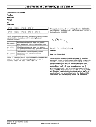
2.4 Identification
The SM-ELV Solutions Module consists of either an SM-Applications or an SM-Applications Lite with the elevator software.
The elevator software version and identity number can be verified in the following parameters:
The software version is displayed in Pr 0.28 [1] (Pr 20.01) software Version in the form of xx.xx.
The software identity number is displayed in Pr 0.29 [1] (Pr 20.02) Software identity number in the form of xx.xx.
To verify the lift software is running, monitor Pr 0.29 [1] (Pr 20.02). This should toggle every 1s between 10614 and -10614.
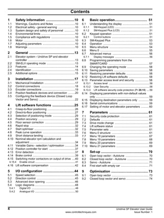
2.5 Additional options
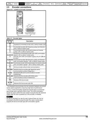
Figure 2-2 Options available with Unidrive SP
* A SMARTCARD is provided with the Unidrive SP as standard.
All Unidrive SP Solutions Modules are colour-coded in order to make identification easy. The following table shows the colour-code key and gives
further details on their function.
Keypad
Automation FieldbusFeedback
SMARTCARD*
CT Comms
cable
External
footprint /
bookcase
EMC filter
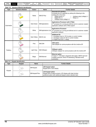
Table 2-2 Solutions Module identification
Type Solutions Module Colour Name Further Details
Feedback
Light Blue SM-Resolver
Resolver interface
Feedback interface for resolvers.
Simulated quadrature encoder outputs
N/A
15-way D-type
converter
Drive encoder input converter
Provides screw terminal interface for encoder wiring and spade
terminal for shield](https://image.slidesharecdn.com/unispelevator-140613204659-phpapp02/85/Uni-sp-elevator-15-320.jpg)
![Safety
Information
General Installation
Lift software
functions
I/O
configuration
Basic
operation
Parameters Set-up Optimisation
Rescue
operation
SMARTCARD
operation
Commissioning
software tools
Diagnostics
26 Unidrive SP Elevator User Guide
www.controltechniques.com Issue Number: 1
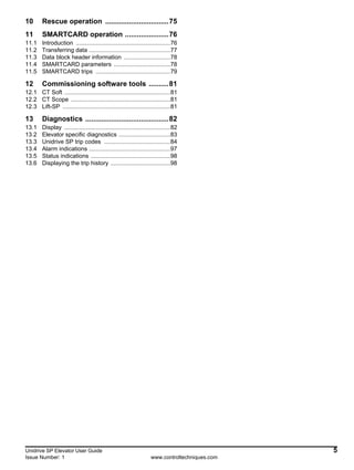
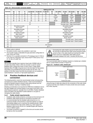
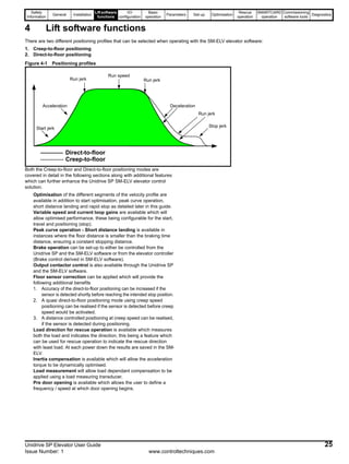
4.1 Creep-to-floor positioning
Positioning with creep-to-floor is used in most applications and is
therefore selected as the default setting for the SM-ELV software
Pr 0.16[3] (Pr 20.13) = 0.
The speed is applied according to the selected floor distance, and the
elevator controller controls the start, travel, deceleration, switches to the
creep-to-floor speed and then positions (stops) at the floor.
The elevator controller selects speeds depending on the distance called
for by selecting the appropriate binary or priority speed configured in the
Unidrive SP and SM-ELV software.
Figure 4-2 Velocity profile with creep-to-floor positioning
For several segments of the velocity profile shown above there are
independent parameters available for example for the Acceleration and
Jerk with which the performance can be optimised.
In addition to controlling the velocity profile, the required deceleration
distance Pr 0.14[3] (Pr 19.08), dependent upon the speed and profile
settings, is calculated and displayed in mm for the activated speed in
Pr 0.14[3] (Pr 19.08).
The deceleration distance depends on the load, as it is not possible to
control the distance.
The measured deceleration distance is displayed after every travel in
Pr 0.15[3] (Pr 19.10) in mm.
N
From SM-ELV software version 1.12 onwards the deceleration distances
for all speeds are displayed in Pr 2.13 to Pr 2.18 and Pr 2.23 to Pr 2.25.
The real time demand on the elevator control system is low due to the
positioning with creep-to-floor. With a typical cycle time of the elevator
controller (5 ... 20 ms) and the elevator drive (8 ms) the minimal
positioning distance with creep speed is calculated as:
• The max creep speed distance is:
Positioning distance [m] ≥ VNominal [m/s] * 30 ms
• The stop accuracy is:
Accuracy [mm] ≤ Vcreep speed [m/s] * 30 ms
• The time required for creep speed is:
Time creep speed [s]= positioning distance [m] / Vcreep speed [m/s]
Speed signals
Creep speed
signal
Level sensor
Pr 0.23 [0] (Pr 19.14)
Pr 0.03 [0] (Pr 2.11)
Pr 0.24 [0] (Pr 19.15)
Pr 0.14 [3] (Pr 19.08)
Pr 0.22 [0] (Pr 19.13)
Pr 0.25 [0] (Pr 19.16)
Pr 0.15 [0] (Pr 18.11)
Pr 0.24 [0] (Pr 19.15)
Pr 0.24 [0] (Pr 19.15)
Pr 0.04 [0] (Pr 2.21)
Calculated deceleration
distance
Pr 0.16 … Pr 0.21[0]
Pr 18.12 … Pr 18.17
V:
Start jerk
Acceleration
Run jerk
Operational speeds
Run jerk
Run jerk
Deceleration
Creep speed
Stop jerk
Stop deceleration
NOTE
Speed (mm/s) Pr 18.12 Pr 18.13 Pr 18.14 Pr 18.15 Pr 18.16 Pr 18.17 Pr 20.02 Pr 20.23 Pr 20.24
Deceleration distance (cm)
Pr 2.13
Pr 0.31 [3]
Pr 2.14
Pr 0.32 [3]
Pr 2.15
Pr 0.33 [3]
Pr 2.16
Pr 0.34 [3]
Pr 2.17
Pr 0.35 [3]
Pr 2.18
Pr 0.36 [3]
Pr 2.23
Pr 0.37 [3]
Pr 2.24
Pr 0.51 [3]
Pr 2.25
Pr 0.52 [3]](https://image.slidesharecdn.com/unispelevator-140613204659-phpapp02/85/Uni-sp-elevator-26-320.jpg)
![Safety
Information
General Installation
Liftsoftware
functions
I/O
configuration
Basic
operation
Parameters Set-up Optimisation
Rescue
operation
SMARTCARD
operation
Commissioning
software tools
Diagnostics
Unidrive SP Elevator User Guide 27
Issue Number: 1 www.controltechniques.com
Figure 4-3 Creep to floor
N
Pr 0.29[2] Pr 18.23 is used to adjust the magnetisation current threshold
level for both Open Loop and Closed Loop Vector operation, the Deflux
motor level is fixed at 200ms as shown above.
For servo operation Pr 0.29[2] Pr 18.23 the magnetisation current
threshold parameter is not required, this parameter can now be used to
define the time taken to deflux the synchronous motor.
4.2 Direct-to-floor positioning
For some applications, especially high-speed elevators and long travel
distance elevators direct-to-floor positioning control is often used with
this overcoming inherent delays normally associated with creep-to-floor
elevators.
With direct-to-floor positioning the speed is applied according to the
selected floor distance. As a function of the distance to the desired final
position, the elevator controller will disable the speed signal, and direct
deceleration to the target position will take place. Creep speed
positioning is not executed nor required. The following graph shows the
characteristics of this motion profile:
Direct to floor positioning should only be used on elevating up to 1m/s
due to the accuracy, above 1m/s floor sensor correction should be
enabled also.
Debouncecontactors(100ms)
FluxMotor=t>100ms
Brakereleasedelay
Pr0.24[1](Pr19.25)
Brakeapplydelay
Pr0.25[1]Pr18.24
DefluxMotor=200ms
t.0 t.1 t.2 t.3 t.5 t.6 t.7t.4
InterlockDelay=>50ms
t.8
Drive active
Direction
Main contactor
Enable
Creep Speed
Brake output
Pre door opening
Creep Speed
Pr 0.15[0] (Pr 18.11)
Pr 0.24[0] (Pr 19.15)
Pr 0.20[1] (Pr 19.17)
TimeforStartOptimiser
Pr0.19[1](Pr19.28)
Kp Position loop (Start)
Refer to section 4.11
Pr 0.22[0] (Pr 19.13)
Kd Position loop (Start)
Kp Speed loop
Ki Speed loop
Current Filter
Kp Current loop
Ki Current loop
MotorcontactordelayPr20.20
Magnetising-Threshold
Speeds
Loadmeasurement
timePr20.08
Pr 0.25 [0] (Pr 19.16)
Pr 0.24[0] (Pr 19.15) Pr 0.16 … Pr 0.24[0]
Pr 18.12 … Pr 18.16
Run jerkRun jerk Operational speeds
Acceleration Deceleration
Run jerk
Pr 0.24[0] (Pr 19.15)Pr 0.24[0] (Pr 19.15)
Start jerk
Pr 0.03[0] (Pr 2.11) Pr 0.04[0] (Pr 2.21)
Pr 0.18[1] (Pr 18.18)
Start optimser speed
Jerk optimser speed
Stop jerk (Creep-to-floor)
Magnetising Current
Stop deceleration (Creep-to-floor)
Pr 0.26[0] (Pr 18.21)
Pr 0.29[2] (Pr 18.23)
Pr 0.19[2] (Pr 19.20)
Refer to section 4.11
Refer to section 4.11
Pr 0.20[2] (Pr 19.12)
Refer to section 4.11
Refer to section 4.11
Terminal 24 (0.3 m/s)
Terminal 25
Terminal 29
Terminal 31
Terminal 28
V1 (T.26) V2 (T.27) V3 (T.5) Vn (T.7)
Pr 10.02
NOTE](https://image.slidesharecdn.com/unispelevator-140613204659-phpapp02/85/Uni-sp-elevator-27-320.jpg)
![Safety
Information
General Installation
Lift software
functions
I/O
configuration
Basic
operation
Parameters Set-up Optimisation
Rescue
operation
SMARTCARD
operation
Commissioning
software tools
Diagnostics
28 Unidrive SP Elevator User Guide
www.controltechniques.com Issue Number: 1
Figure 4-4 Velocity profile with direct-to-floor positioning
N
Direct to floor is enabled with Pr 20.13
For several of the positioning profile segments different parameters are
available for example Acceleration and their associated Jerks, with
which the performance of the direct-to-floor can be optimised. The
relevant parameters are as shown above.
To go directly to the target, the deceleration is dependent on the required
stopping distance. The maximum deceleration is limited by Pr 0.04[0]
(Pr 2.21) stop deceleration. If the correction of the deceleration rate is
not sufficient, it is possible that the car will stop too late and hence
overshoot the floor level.
The direct to floor positioning mode, uses as a reference the selected
speed and profile settings to calculate and display the deceleration
distance in Pr 0.14[3] (Pr 19.08) in mm, calculated deceleration distance.
The deceleration distance is controlled to this value independent of the
load. The actual distance moved is displayed in Pr 0.15[3] (Pr 19.10) in
mm.
Figure 4-5 Direct to floor
Speed signals
Stop signal**
Level sensor
Pr 0.23 [0] (Pr 19.14)
Pr 0.03 (Pr 2.11)
Pr 0.24 [0] (Pr 19.15)
Pr 0.14 [3] (Pr 19.08)
Pr 0.24 [0] (Pr 19.15)
Pr 0.24 [0] (Pr 19.15)
Pr 0.04 (Pr 2.21)
Calculated deceleration
distance
Pr 0.16 … Pr 0.21[0]
Pr 18.12 … Pr 18.17
V:
** Only if direct-to-floor positioning with stop signal
Start jerk
Accelleration
Run jerk Run jerk
Run jerk
Deceleration
Operational speeds
NOTE
Debouncecontactors(100ms)
FluxMotor=t>100ms
Brakereleasedelay
Pr0.24[1](Pr19.25)
Brakeapplydelay
Pr0.25[1]Pr18.24
DefluxMotor=200ms
t.0 t.1 t.2 t.3 t.5 t.6 t.7t.4
InterlockDelay=>50ms
t.8
Drive active
Direction
Main contactor
Enable
Brake output
Pre door opening
Pr 0.24[0] (Pr 19.15)
Pr 0.20[1] (Pr 19.17)
TimeforStartOptimiser
Pr0.19[1](Pr19.28)
Kp Position loop (Start)
Refer to section 4.11
Kd Position loop (Start)
Kp Speed loop
Ki Speed loop
Current Filter
Kp Current loop
Ki Current loop
MotorcontactordelayPr20.20
Magnetising-Threshold
Speeds
Loadmeasurement
timePr20.08
Pr 0.24[0] (Pr 19.15) Pr 0.16 … Pr 0.24[0]
Pr 18.12 … Pr 18.16
Run jerkRun jerk Operational speeds
Acceleration Deceleration
Run jerk
Pr 0.24[0] (Pr 19.15)Pr 0.24[0] (Pr 19.15)
Start jerk
Pr 0.03[0] (Pr 2.11) Pr 0.04[0] (Pr 2.21)
Pr 0.18[1] (Pr 18.18)
Start optimser speed
Jerk optimser speed
Magnetising Current
Pr 0.26[0] (Pr 18.21)
Pr 0.29[2] (Pr 18.23)
Pr 0.19[2] (Pr 19.20)
Refer to section 4.11
Refer to section 4.11
Pr 0.20[2] (Pr 19.12)
Refer to section 4.11
Refer to section 4.11
Terminal 24 (0.3 m/s)
Terminal 25
Terminal 31
Terminal 28
V1 (T.26) V2 (T.27) V3 (T.5) Vn (T.7)
Pr 10.02](https://image.slidesharecdn.com/unispelevator-140613204659-phpapp02/85/Uni-sp-elevator-28-320.jpg)
![Safety
Information
General Installation
Liftsoftware
functions
I/O
configuration
Basic
operation
Parameters Set-up Optimisation
Rescue
operation
SMARTCARD
operation
Commissioning
software tools
Diagnostics
Unidrive SP Elevator User Guide 29
Issue Number: 1 www.controltechniques.com
N
Pr 0.29[2] Pr 18.23 is used to adjust the magnetisation current threshold
level for both Open Loop and Closed Loop Vector operation, the Deflux
motor level is fixed at 200ms as shown above.
For servo operation Pr 0.29[2] Pr 18.23 the magnetisation current
threshold parameter is not required, this parameter can now be used to
define the time taken to deflux the synchronous motor.
4.3 Selection of positioning mode
The direct-to-floor / creep-to-floor positioning modes are enabled with
parameter Pr 0.16[3] (Pr 20.13). The following settings can be selected:
Pr 0.16[3] (Pr 20.13) = 0 Direct-to-floor positioning disabled. Creep-to-
floor active
Pr 0.16[3] (Pr 20.13) = 1 Direct-to-floor positioning with Stop signal via
analogue input 1 (T.5)
Pr 0.16[3] (Pr 20.13) = 2 Direct-to-floor positioning with Stop signal via
analogue input 2 (T.7)
Pr 0.16[3] (Pr 20.13) = 3 Direct-to-floor positioning with Stop signal via
analogue input 3 (T. 8)
Pr 0.16[3] (Pr 20.13) = 4 Direct-to-floor positioning with disable the
speed signals (controlling)
4.4 Position accuracy
The deceleration distance is calculated from the activated speed. If the
speed signal is deactivated (Pr 0.16 [3], (Pr 20.13) = 4), or the stop
signal is activated (Pr 0.16 [3] (Pr 20.13) = 1...3) the calculated
deceleration distance will be controlled independent of the load level.
At higher travel speeds the actual position at which the car will stop is
highly dependent on the time when deceleration begins. For example, if
the I/O read cycle time of the drives inputs is 1ms, and if the cycle time of
the elevator controller is 1ms the position accuracy is:
Accuracy [mm] = Vnominal [m/s] * 2 mm.
Because of this, the usage of direct-to-floor positioning is limited to about
1m/s. At higher speeds, additional distance control for accurate stopping
should be used. (Additional floor sensor correction can be used to
control the final distance moved, see section 4.5 Floor sensor
correction on page 29).
N
From SM-ELV software version 1.12 onwards the deceleration distances
for all speeds are displayed in Pr 2.13 to Pr 2.18 and Pr 2.23 to Pr 2.25.
4.5 Floor sensor correction
Independent of the selected profile additional floor sensor correction can
be utilised. Improved accurate distance correction is possible if a floor
sensor can be detected in the range of 50-500mm before the flush or
level with floor target position.
Floor sensor correction should be used with direct-to-floor positioning
control on elevators with speeds in excess of 1m/s. This ensures
maximum accuracy.
To enable floor sensor correction, the following parameters should be set
up:
Pr 0.17[3] (Pr 19.42)
Pr 0.19[3] (Pr 20.14)
Pr 0.20[3] (Pr 18.19)
Given this:
• Rope slip can be compensated (as long as the normal stopping
distance is short without the additional compensation provided by
the direct-to-floor positioning mode).
• A quasi direct-to-floor positioning can be realised if the additional
sensor is detected before positioning at creep speed, (creep-to-floor
positioning mode).
• Floor sensor correction can be utilised if detected during the
positioning travel at creep speed, in the creep-to-floor positioning
mode.
N
The floor sensor correction or the distance controlled creep speed can
only be used in closed loop or servo mode. In open loop mode, a normal
deceleration with the programmed ramp can only be implemented.
N
If the floor sensor enable Pr 0.17[3] (Pr 19.42) = 0 all values concerning
floor sensors can be checked for correct operation. All measured values,
which are required for the floor sensor, for example the deceleration
distance, time from the floor sensor and the speed at floor sensor are
displayed and can be checked. This means, that all functions of the floor
sensor correction can be proofed, prior to being enabled.
The floor sensor correction uses as a reference, the floor sensor target
distance defined by the user in Pr 0.20[3] (Pr 18.19) in mm. The floor
sensor target distance is controlled independent of the load. The
remaining distance to the floor sensor in mm is displayed Pr 0.21[3]
(Pr 18.09). Additionally, Pr 0.23[3] (Pr 20.05) displays the time from floor
sensor active to the stop, and Pr 0.22[3] (Pr 19.09) displays the speed at
the floor sensor correction activation.
If the Stop distance is too low, or the floor sensor signal given at too high
a speed, it is possible that the car may not stop smoothly and a hard
stop will occur (Figure 4-6 - profile (3))
The floor sensor correction is activated based upon the settings of
Pr 0.19[3] (Pr 20.14) which is used to set-up the source for the external
floor sensor correction signal:
1. Pr 0.19[3] (Pr 20.14) = 0 Floor sensor correction disabled
2. Pr 0.19[3] (Pr 20.14) = 1 Floor sensor correction = Analogue input 1
3. Pr 0.19[3] (Pr 20.14) = 2 Floor sensor correction = Analogue input 2
4. Pr 0.19[3] (Pr 20.14) = 3 Floor sensor correction = Analogue input 3
5. Pr 0.19[3] (Pr 20.14) = 4 Distance controlled stopping distance
4.5.1 Floor sensor correction, Analogue input
Conditions 1, 2, or 3: (Pr 0.19[3] (Pr 20.14) = 1,2 or 3 (Figure 4-6 -
profile (2))
When the floor sensor correction signal is activated, the floor sensor
target distance is controlled independant of load. Because of direct
deceleration from a higher speed, the real time demand on the control
system is high and dependent upon the parameter settings and I/O
speed. For example, if the cycle time of the elevator controller is 1ms,
and the drives inputs are also 1ms the position accuracy is:
Accuracy [mm] = vspeed at floor sensor active (Pr 19.09) [m/s] * 2 mm
It should be noted that the floor sensor correction signal should be
activated instantaneously at that position which is Pr 0.20[3] (Pr 18.19)
floor sensor target distance away from the floor sensor in mm.
The stop signal can be used for all speeds. The creep speed signal can be
deactivated at any time after the floor sensor correction signal is activated.
N
If the creep speed signal is still active at standstill the motor will
accelerate to creep speed.
NOTE
NOTE
NOTE
NOTE
NOTE](https://image.slidesharecdn.com/unispelevator-140613204659-phpapp02/85/Uni-sp-elevator-29-320.jpg)
![Safety
Information
General Installation
Lift software
functions
I/O
configuration
Basic
operation
Parameters Set-up Optimisation
Rescue
operation
SMARTCARD
operation
Commissioning
software tools
Diagnostics
30 Unidrive SP Elevator User Guide
www.controltechniques.com Issue Number: 1
Figure 4-6 Floor sensor correction profiles
4.5.2 Distance controlled creep speed
Condition 4: (Pr 0.19[3] (Pr 20.14) = 4 (Figure 4-6 - profile (1))
If the creep speed signal is deactivated, the controlled stopping distance
in Pr 0.20[3] (Pr 18.19) will be active. The relevant profile parameters
are Pr 0.22[0] (Pr 19.13) deceleration, and Pr 0.25[0] (Pr 19.16) stop jerk
(creep-to-floor). In this case, because the deceleration is from creep
speed, the real time demand to the elevator controller is low. For
example if the cycle time of the elevator controller is 10ms and the
elevator drive 1ms, the accuracy can be calculated and the stop
accuracy would be:
Accuracy [mm] <= vcreep speed [m/s] * 11 mm
4.5.3 Deceleration and stopping distance
calculation
If the speed or profile parameters are changed then the deceleration and
stopping distances will change. The elevator controller can compensate
for these changes by recalculating the final deceleration to achieve the
floor sensor correction distance through a “learn” if this is possible.
However to reach the target distance, profile parameters are limited for
deceleration to 2 x Pr 0.04[0] (Pr 2.21) and the jerk to a maximum value
of Pr 0.25[0] (Pr 19.16). If the stop distance is too low or the floor sensor
signal was given at too high a speed the car may not be able to stop
smoothly and therefore a hard stop will be implemented. To change the
parameters in the elevator controller correctly, the drive calculates the
deceleration and stop distances and displays them in the following
parameters:
Table 4-1 Floor sensor correction parameters
The profile parameters and the creep speed setting are used for
calculating distances. At default settings, the creep speed in Pr 0.15[0]
(Pr 18.11) is used. This assignment can be changed through Pr 20.12
creep speed parameter.
N
At completion of the floor sensor correction, Pr 0.21[3] (Pr 18.09) = 0
(±1), Pr 18.10 the reference selector should be 1810 (no reference
selected).
N
The point at which the floor sensor signal (Analogue input 1 (T.5) input 2
(T.7) or input 3 (T.8) if Pr 0.19[3] (Pr 20.14) = 1, 2 or 3) becomes active is
usually between 50 and 500mm prior to the floor level (above 500mm
the accuracy at the floor level will be reduced).
N
If Pr 0.19[3] (Pr 20.14) = 4 then the distance controlled creep speed is
selected, here the floor sensor correction signal is activated during the
creep speed.
Speed signals
Floor sensor signal**
Creep speed
Floor sensor
** Only if floor sensor available
Pr 0.24[0] (Pr 19.15)
Pr 0.04[0] (Pr 2.21)
Pr 0.15[0] (Pr 18.11)
Pr 0.14 [3] (Pr 19.08)
Target correction distance
(1) (2) (3)
Pr 0.24[0] (Pr 19.15)
Creep speed
Run jerk
Deceleration
Run jerk
Floor sensor active
Parameter
Distance controlled
creep speed
Direct-to-floor
Pr 0.17[3]
(Pr 19.42)
Floor sensor correction enable = 1
Pr 0.19[3]
(Pr 20.14)
Source for floor sensor correction
Pr 0.22[3]
(Pr 19.09)
N/A
Speed at floor sensor
correction activation
in mm/s
Pr 0.20[3]
(Pr 18.19)
Floor sensor correction target distance
Pr 0.29[3]
(Pr 19.05)
Stopping distance (from
V1 to V = 0) in mm
Stopping distance in
mm
Pr 0.14[3]
(Pr 19.08)
Calculated deceleration
distance from Vset to V1
in mm
Calculated
deceleration distance
from Vset to 0 in mm
Pr 0.15[3]
(Pr 19.10)
Measured deceleration
distance from Vset to V1
Measured
deceleration distance
from Vset to 0 in mm
Pr 0.21[3]
(Pr 18.09)
Remaining floor sensor distance
Pr 0.23[3]
(Pr 20.05)
Time from floor sensor active
NOTE
NOTE
NOTE](https://image.slidesharecdn.com/unispelevator-140613204659-phpapp02/85/Uni-sp-elevator-30-320.jpg)
![Safety
Information
General Installation
Liftsoftware
functions
I/O
configuration
Basic
operation
Parameters Set-up Optimisation
Rescue
operation
SMARTCARD
operation
Commissioning
software tools
Diagnostics
Unidrive SP Elevator User Guide 31
Issue Number: 1 www.controltechniques.com
Figure 4-7 Distance controlled creep speed - floor sensor correction
Figure 4-8 Direct to floor - floor sensor correction
Brake output
Brake delay
Direction signal
Creep speed selection
Pr 0.24[0] (Pr 19.15)
Pr 0.04[0] (Pr 2.21)
Pr 0.20[3] (Pr 18.19)
Floor sensor target
correction distance
Run jerk
Deceleration
Pr 0.25[1] (Pr 18.24)
Pr 0.19[4] (Pr 18.31)
Drive enable Terminal 31
Terminal 28
Zero speed
Measured deceleration distance
Remaining floor sensor distance
Floor sensor active
Pr 10.03
Calculated deceleration distance
Pr 0.15[3] (Pr 19.10)
Pr 0.14[3] (Pr 19.08)
Pr 0.21[3] (Pr 18.09)
Floor sensor correction enable Pr 0.17[3] (Pr 19.42)
Pr 0.24[0] (Pr 19.15)
Run jerk
Pr 0.22[0] (Pr 19.13)
Stop deceleration
Floor sensor active
Brake output
Brake delay
Direction signal
Speed selection
Pr 0.24[0] (Pr 19.15)
Pr 0.04[0] (Pr 2.21)
Pr 0.20[3] (Pr 18.19)
Floor sensor target
correction distance
Run jerk
Deceleration
SM-ELV calculated jerk - from
distance to target and actual speed
Pr 0.25[1] (Pr 18.24)
Pr 0.19[4] (Pr 18.31)
Drive enable Terminal 31
Terminal 28
Zero speed
Measured deceleration distance
Remaining floor sensor distance
Floor sensor active
Pr 10.03
Calculated deceleration distance
Pr 0.15[3] (Pr 19.10)
Pr 0.14[3] (Pr 19.08)
Pr 0.21[3] (Pr 18.09)
Floor sensor correction enable Pr 0.17[3] (Pr 19.42)
Floor sensor
active](https://image.slidesharecdn.com/unispelevator-140613204659-phpapp02/85/Uni-sp-elevator-31-320.jpg)
![Safety
Information
General Installation
Lift software
functions
I/O
configuration
Basic
operation
Parameters Set-up Optimisation
Rescue
operation
SMARTCARD
operation
Commissioning
software tools
Diagnostics
32 Unidrive SP Elevator User Guide
www.controltechniques.com Issue Number: 1
4.6 Rapid stop
A rapid stop function has been introduced with software version 1.10
onwards which is enabled by setting Pr 19.49 = 1. The rapid stop feature
is available mainly for commissioning and inspection of the elevator,
providing the following features:
• Offers user defined Rapid stop profile
• Provides faster stopping, rather than following the standard
deceleration and jerks that may be too long during commissioning
and inspection.
• Can overcome hard stops and be less aggressive during short
movements during commissioning and installation.
If rapid stop is enabled, when selecting a speed with the value of 0 mm/s
for the deceleration, the deceleration rate in Pr 21.05 is selected which is
available for the rapid stop deceleration only (Closed Loop in m/s2 /Open
Loop in cm/s2). The deceleration jerk is set to 200 ms in order to run as
smoothly as possible.
Figure 4-9 Rapid stop
4.7 Start optimiser
To overcome static friction in the elevator arrangement or to overcome
starting difficulties a start optimiser function is available.
This function is activated by setting the start optimisation time in
Pr 0.19[1] (Pr 19.28) > 0. Also a target speed for the start optimiser must
be set in Pr 0.18[1] (Pr 18.18) > 0, along with the start optimiser jerk in
Pr 0.20[1] (Pr 19.17).
Table 4-2 Softstart parameters
Figure 4-10 Start profile optimisation
N
If the target speed set in Pr 0.18[1] (Pr 18.18) is not reached during the
time defined in Pr 0.19[1] (Pr 19.28) there will be a continuous transition
to the nominal acceleration.
Parameter Function Detail
Pr 0.18 [1]
(Pr 18.18)
Target speed in mm/s
for start optimisation
Setting between 2...5mm/s.
Pr 0.19 [1]
(Pr 19.28)
Time in ms for start
optimisation
Setting between 500 to 800ms.
Pr 0.20 [1]
(Pr 19.17)
Jerk in mm/s3
for
starting optimisation
Setting from 10 up to 20 (must
be less than the acceleration
jerk in Pr 0.22) smaller values
will provide smoother but slower
acceleration.
Inspection speed Rapid stop speed
Standard deceleration / stop
Rapid deceleration / stop
Pr 0.19 [1] (Pr 19.28)
Pr 0.20 [1] (Pr 19.17)
Pr 0.18 [1] (Pr 18.18)
Jerk for start optimiser
Time for start optimiser
Sped for start
optimiser
NOTE](https://image.slidesharecdn.com/unispelevator-140613204659-phpapp02/85/Uni-sp-elevator-32-320.jpg)
![Safety
Information
General Installation
Liftsoftware
functions
I/O
configuration
Basic
operation
Parameters Set-up Optimisation
Rescue
operation
SMARTCARD
operation
Commissioning
software tools
Diagnostics
Unidrive SP Elevator User Guide 33
Issue Number: 1 www.controltechniques.com
4.8 Peak curve operation
This function guarantees a constant stopping distance, independent of the
moment when the signal to stop occurs. This allows the use of a single
speed for different floor levelling distances. Peak curve operation modifies
the maximum operating speed to ensure that the required distance is
achieved and floor level is reached. The peak curve operation can be used
during both Creep-to-floor operation and Distance controlled creep speed
(Floor sensor correction mode).
The peak curve operation is enabled by setting Pr 0.27 [1] (Pr 18.47) = 1
(Default = 0).
Depending on the speed when the speed signal is disabled, 3 different
results can occur:
• If the final speed is achieved there is no influence on the speed profile.
• If there is increasing or constant acceleration, braking occurs with the
normal profile parameters in a calculated time.
• During deceleration and the transition to a stop, the profile
parameters are automatically adjusted.
Figure 4-11 Peak curve operation
The reference speed before and after speed reduction is used as the
calculation base for the controlled stopping distance.
The Set-point peak curve distance is calculated from the profile
parameters and displayed in Pr 0.27[3] (Pr 19.06). This value is
equivalent to the deceleration distance for the applied speed.
The deceleration distance is measured during peak curve operation and
displayed in Pr 0.28[3] (Pr 19.07).
4.9 Short distance landing
If the floor distance is smaller than the braking time distance from the
selected speed, then the peak curve operation cannot be used. This is
the case if the floor distance is less than 0.7 m for example. For such
small floor distance, the elevator software function provides the short
distance landing with real distance control. Short distance landing is
enabled with Pr 18.35 via an additional digital input.
The short distance is defined in Pr 18.20 and enabled with a digital input
from the elevator controller at the floor level (less then 0.7m)
The control signals for creep speed and short distance landing must be
applied simultaneously. The speed profile is internally calculated in order
that the creep speed is reached after the short distance Pr 0.26[3] (Pr
18.20). If the creep speed command is disabled, the elevator drive stops
the car with the set deceleration.
Figure 4-12 Short distance landing
Pr 0.14 [3]
(Pr 19.08)
V1 ... V3
Creep speed
Peak curve operation
Calculated
deceleration
distance
Pr 0.27[3]
(Pr 19.06)
Set-point
peak curve
distance
Standard operation
Pr 18.35 - Enable
Creep speed
Pr 0.26 [3] (Pr 18.20)
Short distance
landing](https://image.slidesharecdn.com/unispelevator-140613204659-phpapp02/85/Uni-sp-elevator-33-320.jpg)
![Safety
Information
General Installation
Lift software
functions
I/O
configuration
Basic
operation
Parameters Set-up Optimisation
Rescue
operation
SMARTCARD
operation
Commissioning
software tools
Diagnostics
34 Unidrive SP Elevator User Guide
www.controltechniques.com Issue Number: 1
4.10 Nominal elevator rpm calculation and
adjustment
The ratio of nominal elevator rpm Pr 0.13[0] (Pr 18.29) to nominal
elevator speed Pr 0.14[0] (Pr 18.30) is as follows. The nominal elevator
rpm Pr 0.13[0] (Pr 18.29) is defined by the mechanical conditions as
follows:
Pr 0.13[0] (Pr 18.29) [n Nominal] = Pr 0.14[0] (Pr 18.30) [v Nominal] * iG * Z
* 60 / (Ω * D * GZ)
Figure 4-13 Elevator parameters
Where:
After adjustment of the above parameters, the calculated nominal
elevator rpm is displayed in Pr 0.13[1] (Pr 18.03) in rpm. With software
version 01.10 onwards the value of Pr 0.13[0] (Pr 18.29) can be set up
automatically by setting Pr 19.31 = 1. The calculations are exact,
however manual adjustment is possible and can be achieved by
changing the value of Pr 0.13[0] (Pr 18.29) as follows:
If the speed of the elevator is too high, the nominal rpm Pr 0.13[0]
(Pr 18.29) should be reduced.
If the speed of the elevator is too low, the nominal rpm Pr 0.13[0]
(Pr 18.29) should be increased.
4.11 Variable Gains - selection /
optimisation
The following variable gains can be used for optimisation of the speed
loop (Kp and Ki) gains, current loop (Kp and Ki) gains and current loop
filter.
There are three settings for the variable gains, one being constant, one
having a user determined transition time and the third having a profile /
travel determined transition time, the options are determined by which
version of lift software you are operating with.
Constant (standard Unidrive SP) gains are available with all SM-ELV
software versions.
User determined transition time
variable speed loop gains for Start and Travel can be activated by
setting Pr 0.21[2] (Pr 18.48) = On as detailed following.
Profile / travel determined transition time = Software version V1.07
and later. These variable speed loop / current loop gains and current
loop filter are enabled by setting Pr 0.21[2] (Pr 18.48), Pr 19.48 = On
as detailed following.
The following sections cover in more detail the variable speed loop and
current loop gain settings along with a variable current loop filter. These
can be configured for the Start, Travel and Positioning (Stop) or just
start; dependant upon the mode being implemented and SM-ELV
software version, detailed as follows. The variable gains will operate in
either Direct-to-floor or Creep-to-floor
Table 4-3 Variable gains
n
Nominal elevator
speed rpm
Pr 0.13[0] (Pr 18.29) in min-1
V
Nominal elevator
speed mm/s
Pr 0.14[0] (Pr 18.30) in mm/s
Z Roping (1, 2, 3 or 4)
Pr 0.14[1] (Pr 20.10)
(1=1:1 / 2=2:1 / 3=3:1 / 4=4:1)
D Sheave Diameter Pr 0.15[1] (Pr 19.29) in mm
ig Gear Ratio Numerator Pr 0.16[1] (Pr 19.30)
GZ
Gear Ratio
Denominator
Pr 0.17[1] (Pr 19.27)
iG / Gz
D n nominal
elevator
speed rpm
Vnominal
elevator
speed mm/s
Mode Active SM-ELV S/W Transition mode
Constant Speed loop gains
Pr 18.48 = 0
Whole profile N/A
Separate Speed loop gains
Pr 18.48 = 1, Pr 19.48 = 0
Start, Travel Pr 19.11 > 0 transition time ms
Separate Speed loop, Current loop gains,
Current demand filter
Pr 18.48 = 1, Pr 19.48 =1
Start, Travel, Positioning (stop) V1.07 onwards Speed controlled transition time.
Separate Speed loop, Current loop gains,
Current demand filter
Pr 18.48 = 1, Pr 19.48 =1
Start, Travel, Positioning (stop) V1.13 onwards
Acceleration
Pr 19.11 = 0 Speed controlled transition time
Pr 19.11 > 0 = transition time ms
Deceleration
Pr 20.30 = 0 Speed controlled transition time
Pr 20.30 > 0 = transition time ms](https://image.slidesharecdn.com/unispelevator-140613204659-phpapp02/85/Uni-sp-elevator-34-320.jpg)
![Safety
Information
General Installation
Liftsoftware
functions
I/O
configuration
Basic
operation
Parameters Set-up Optimisation
Rescue
operation
SMARTCARD
operation
Commissioning
software tools
Diagnostics
Unidrive SP Elevator User Guide 35
Issue Number: 1 www.controltechniques.com
4.11.1 Constant gains
Pr 0.21[2] (Pr 18.48), Pr 19.48 = OFF
Following are the standard speed and current loop optimisation
parameters which are only destinations in the variable gain set-up and
written to from the SM-ELV software, Pr 0.21[2] (Pr 18.48), Pr 19.48 =
OFF.
If Pr 0.21[2] (Pr 18.48), Pr 19.48 = OFF constant gains are used and can
be adjusted in the parameters as shown in Table 4-4.
Table 4-4 Constant speed / current loop gains
Pr 0.21[2] (Pr 18.48), Pr 19.48 = OFF
N
The speed loop Kp and Ki gains in Pr 0.07 (Pr 3.10) and Pr 0.08
(Pr 3.11) are for display only when variable gains are selected with
Pr 0.21[2] (Pr 18.48) and Pr 19.48, and therefore cannot be modified.
The values in Pr 0.07 (Pr 3.10) and Pr 0.08 (Pr 3.11) show the active
speed loop gain. When the variable gains are inactive the values in
Pr 0.07 (Pr 3.10) and Pr 0.08 (Pr 3.11) can be modified as normal.
4.11.2 Seperate speed loop gains
Pr 0.21[2] (Pr 18.48) = On, Pr 19.48 = OFF
When using planetary gearboxes it is advisable to separate the speed
loop gains for Start and Travel. This can be activated by setting
Pr 0.21[2] (Pr 18.48) = On and offers various speed loop gain settings
for travel Pr 0.23[2] (Pr 18.25) / Pr 0.24[2] (Pr 18.26) and Start Pr 0.25[2]
(Pr 18.27) / Pr 0.26[2] (Pr 18.28), along with a programmable current
loop filter for start and travel as shown in Table 4-5 .
These parameters are switched depending on the transition time, set-up
by the user. Pr 0.22[2] (Pr 19.11) defines the transition time between
start and travel for the P and I speed loop gains and current loop filter.
The transition time should be set-up to avoid switching vibrations /
instability. For Start the speed loop gains can be up to 2 to 3 times the
setting required for the Travel, this equating to a reduction of the position
error at brake opening to between 1/4 and 1/9.
The following parameters are available for optimising the speed loop
gains, and current loop filter.
Table 4-5 Variable gains Pr 0.21[2] ,Pr 18.48 = On, Pr 19.48 = OFF
Parameter Detail
Speed loop
Pr 0.07
(Pr 3.10)
P- Gain
Higher values improve the
smooth running and the
stiffness. Values recommended
between 0.100 (Incremental
Encoder) and 0.500 (SinCos)
Pr 0.08
(Pr 3.11)
I - Gain
Higher values will decrease the
effect of the load with smaller
values reducing the overshoot
of the speed loop. Usually
adjust the value between 1.00
and 5.00
Pr 0.09
(Pr 3.12)
D - Gain
Operates as a feed forward
term in the speed loop.
Increased values will reduce
overshoot in the speed loop.
However this is normally not
used and set to 0
Pr 3.42
Speed
feedback
filter in ms
Used with high inertia loads and
high gains to smooth the torque
demand and prevent latch up
effects of the speed loop.
Current loop
(Pr 4.13) P - Gain
This value should be derived
from the stationary auto tune
and may require adjustment if
acoustic noise or current
instability is present: ± 50
(Pr 4.14) I - Gain
This value should be derived
from the stationary auto tune
and may require adjustment if
acoustic noise or current
instability is present: ± 100
Pr 0.14[2]
(Pr 4.12)
Torque
demand
filter in ms
Acts in the speed loop output,
reducing acoustic noise caused
by high-speed loop gains.
Typical values are between 0
and 5
NOTE
Parameter Function Detail
Pr 0.23[2]
(Pr 18.25)
Speed loop
P gain - Travel
Increasing value improves true running
and rigidity. Set values between 1000
(encoder) and 5000 (SinCos)
Pr 0.24[2]
(Pr 18.26)
Speed loop
I gain - Travel
Increasing value reduces deviation.
Reducing value reduces overshooting.
Approx. 10...40% of Pr 0.23[2]
(Pr 18.25)
Pr 0.25[2]
(Pr 18.27)
Speed loop
P gain - Start
Increasing value improves rigidity. Set
values between 2000 (encoder) and
10000 (SinCos)
Pr 0.26[2]
(Pr 18.28)
Speed loop
I gain - Start
Increasing value reduces angle
deviation and jolting at start. Approx. 30
– 80% of Pr 0.25[2] (Pr18.27)
Pr 0.22[2]
(Pr 19.11)
Gaintransition
time in ms
Changeover time for the speed loop
gains from start to travel setting,
beginning with the start
Pr 0.14[2]
(Pr 04.12)
Current filter
Travel
Current loop output filter. Reduces
control noise by fine adjustment of
torque demand.
Pr 0.13[2]
(Pr 04.23)
Current filter
Start
Reduces control noise at the start, only
if Pr 19.34 = 0, otherwise Pr 4.12
applies also for start.
Pr 0.15[2]
(Pr 19.34)
Current filter
Fixed
Activates fixed current filter for start and
travel
Pr 0.38[0]
(Pr 4.13)
Current loop P
gain
Fixed Kp gain
Pr 0.39[0]
(Pr 4.14)
Current loop I
gain
Fixed Ki gain](https://image.slidesharecdn.com/unispelevator-140613204659-phpapp02/85/Uni-sp-elevator-35-320.jpg)
![Safety
Information
General Installation
Lift software
functions
I/O
configuration
Basic
operation
Parameters Set-up Optimisation
Rescue
operation
SMARTCARD
operation
Commissioning
software tools
Diagnostics
36 Unidrive SP Elevator User Guide
www.controltechniques.com Issue Number: 1
Figure 4-14 Start to travel variable gains
4.11.3 Seperate speed loop and current loop gains and
current demand filter, SM-ELV V1.07 onwards
Pr 0.21[2] (Pr 18.48), Pr 19.48 = On
With this procedure each travel section can be allocated its own gain setting.
This procedure is used with critical lifts where the above procedure is not
sufficient or if gains are necessary for the positioning (stop) that are different
from those required for constant travel, and start.
The transfer between the gains is controlled either linearly with the speed or
using a user defined transition time in Pr 19.11 and Pr 20.30.
The transfer of the gains linearly with speed in enabled by setting both
Pr 19.11 and Pr 20.30 = 0 to enable user defined transition times enter
values in Pr 19.11 and Pr 20.30.
The following settings are used:
Table 4-6 Variable gains Pr 0.21[2] (Pr 18.48), Pr 19.48 = On
Also refer to Figure 4-15 which details all parameters associated to the
set-up and adjustment of the variable gains.
Kp Speed loop
Ki Speed loop
Current loop filter
Current loop filter
Pr 18.27
Pr 18.28
Pr 4.12
Pr 18.25
Pr 18.26
Pr 4.12Pr 4.23
(Pr 19.34 = 1)
(Pr 19.34 = 0)
Pr 19.11
Function Start Travel Positioning
Speed Loop P gain Pr 18.27 Pr 18.25 Pr 20.27
Speed Loop I gain Pr 18.28 Pr 18.26 Pr 20.28
Current Loop filter Pr 04.23 Pr 04.12 Pr 21.16
Current Loop P gain Pr 20.25 Pr 04.13 Pr 21.22
Current Loop I gain Pr 20.26 Pr 04.14 Pr 21.23
Transition time Start Pr 19.11 N/A N/A
Transition time Stop N/A N/A Pr 20.30](https://image.slidesharecdn.com/unispelevator-140613204659-phpapp02/85/Uni-sp-elevator-36-320.jpg)
![Safety
Information
General Installation
Liftsoftware
functions
I/O
configuration
Basic
operation
Parameters Set-up Optimisation
Rescue
operation
SMARTCARD
operation
Commissioning
software tools
Diagnostics
Unidrive SP Elevator User Guide 37
Issue Number: 1 www.controltechniques.com
Figure 4-15 Start, travel, positioning variable gains
4.12 Position controller for start
With both gearless lifts and planetary gears a position controller is
particularly suitable for the start, this prevents any movement of the
motor during brake opening. The position controller is made up of both a
Proportional and Derivative term.
This feature will attempt to hold the car in position during opening of the
brake and is only active whilst the brake is being opened. Once the
motor starts the position controller then becomes inactive.
This position controller has the same objective as the separate travel
and start variable gains but works independently of these. The two
procedures, Position controller for start and Variable gains can however
be used at the same time. However, under normal circumstances the
variable gains should be sufficient to eliminate any jerk during opening of
the brake.
When setting the P gain, Pr 0.19[2] (Pr 19.20) to > 0 the car is always
pulled back into position during opening the brake. The maximum
detectable position error is determined by the level of Pr 0.19[2]
(Pr 19.20). Settings from 3 up to 30 are recommended.
The D gain Pr 0.20[2] (Pr 19.12) counteracts a detectably quick change
of position. Settings from 10 up to 100 are recommended. This helps the
P position control and performs more minor compensation procedures
with slight deviations. The set values are limited by the stiffness of the
speed loop gains, which are determined essentially by the speed
feedback device being used (SinCos encoders being far superior (higher
resolution) to standard incremental encoders or resolvers).
N
The position controller for start only operates if a speed has been
selected (Pr 0.28[0] Pr 18.10 > 1810). The position controller is
operating when the display shows “run”, and a speed is selected
(Pr 0.28)[0] (Pr 18.10) >1810). If STOP is displayed, the position
controller is not operating as no speed is being selected.
4.13 Error detection
The following speed and distance error detection features are used to
protect against the following possible failure modes:
Table 4-7 Position controller parameters
• Errors in the motor connection and phase co-ordination
• Errors in the encoder connection and encoder functionality
• Errors in the motor model including feedback phase angle
(brushless synchronous motors)
Figure 4-16 Error detection
Pr 18.27
Pr 18.28
Pr 20.25
Pr 20.26
Pr 18.25
Pr 18.26
Pr 4.13
Pr 4.14
Pr 4.12
Pr 20.27
Pr 20.27
Pr 21.22
Pr 21.23
Pr 21.16
Pr 4.23
Kp Current loop
Ki Current loop
Current loop filter
Kp Speed loop
Ki Speed loop
Pr 19.11 Pr 20.30
NOTE
Parameter Function Detail
Pr 0.19[2]
(Pr 19.20)
Start P gain
Values > 0 cause the position to be held
when opening the brake. Greater values
reduce the jerk when transferring the load.
Recommended values are between 3 and
30.
Pr 0.20[2]
(Pr 19.12)
Start D gain
Values > 0 cause the position to change
quickly when opening the brake and thus
reduce the jerk when transferring the load.
Recommended values are between 10 and
100.
Pr 19.24 Speed Error Threshold
Pr 19.18 Distance Error Threshold
Distance Error
Speed Error
Pr 19.24 = 0 Speed Error Detection Disabled
Pr 19.18 = 0 Distance Error Detection Disabled](https://image.slidesharecdn.com/unispelevator-140613204659-phpapp02/85/Uni-sp-elevator-37-320.jpg)
![Safety
Information
General Installation
Lift software
functions
I/O
configuration
Basic
operation
Parameters Set-up Optimisation
Rescue
operation
SMARTCARD
operation
Commissioning
software tools
Diagnostics
38 Unidrive SP Elevator User Guide
www.controltechniques.com Issue Number: 1
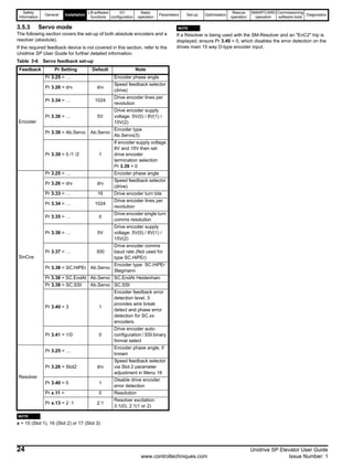
4.13.1 Open loop
Speed Error Detection (Trip 70)
For open loop mode the error detection is activated once the drive
reaches current limit operation with the trip being generated after the
time defined in Pr 19.24 (2s default). Pr 19.24 is used to define the
allowable time to operate in current limit, high values will result in the
detection being disabled.
4.13.2 Closed loop
Speed Error Detection (Trip 70)
The speed error is calculated from the difference between the ramp
speed Pr 19.03 and to the actual speed of the motor in Pr 19.02.
The speed error is compared with the user setting of the allowable
threshold set in Pr 0.26[4] (Pr 19.24). If the threshold is exceeded for
more than 100msec a Trip 70 is generated by the SM-ELV elevator
software.
The speed error during one travel is displayed in Pr 0.25[4] (Pr 18.07)
independent of the activation of the speed error detection. The display is
reset to 0 at each start. The Speed error detection can be disabled by
setting Pr 0.26[4] (Pr 19.24) = 0.
Distance Error Detection (Trip 71)
The distance error is the integral of the difference between the ramp
speed Pr 19.03 and the actual speed of the motor Pr 19.02.
The distance error is compared with an allowable threshold set in
Pr 0.28[4] (Pr 19.18). If the distance error exceeds the user defined
threshold, a Trip 71 is generated.
The distance error during one travel is displayed in Pr 0.27[4] (Pr 18.06)
independent of the activation of the error detection. The display is reset
to 0 at each start.
The distance error detection can be disabled by setting Pr 0.28[4]
(Pr 19.18) = 0 (maximum distance error threshold).
4.13.3 Thermal
Temperature (Trip 73)
The SM-ELV software monitors the drive temperatures if these exceed
the lower limit set in Pr 70.81 (default 0°C, maximum -10°C) a Trip 73
will be generated. This trip is present to protect the drive when starting in
cold conditions.
Figure 4-17 Error detection
4.13.4 Motor error detection
In addition to the speed and distance error detection used to ensure
correct operation, there are an additional two error detection features
that are available for the motor connected to the elevator drive.
The two additional error detection features being (1) Motor Fluxed
Detection and (2) Motor Phase Loss Detection. As with the speed and
distance error detection there are trips associated,
Motor fluxed detection (Trip 76)
The motor fluxed error detection should be used to detect whether the
motor is sufficiently magnetised, and can also be used for example to
detect if there is a fault in the motor contactors at the output of the drive
(contactors not closing).
This feature is available for induction motors operating in either Open
loop or Closed loop vector.
The motor flux level can be viewed in Pr 20.07 Motor flux level, with the
error detection level being determined by Pr 0.29 [2] (Pr 18.23) the Motor
magnetised threshold. Once the threshold has been reached the motor
is then correctly magnetised and Pr 0.18 [4] (Pr 18.43) Motor
magnetised will change to ON.
If the motor magnetised threshold Pr 0.29 [2] (Pr 18.23) is not reached
2s after T.31 is closed (motor contactor) a Trip 76 will be generated.
Motor Phase Loss Detection (Trip 77)
This error detection is used to detect a motor phase loss at the output of
the drive to the motor.
The phase loss trip generated is a Trip 77 and will become active after
200ms of a motor phase loss.
The error detection is enabled with Pr 19.43 Phase Loss Detection
Enable.
Pr 18.30
Pr 18.29
Ratio
inverted
0
1
Pr 19.18
Trip 71
Pr 19.24
Trip 70
1 Second
Speed
error trip
Distance
error trip
Pr 18.06
Pr 18.07
Speed
error
Distance
error
Maximum
distance error
threshold
Maximum speed
error threshold
Pr 3.02
Pr 3.01
Speed reference
Speed feedback
Pr 18.30
100](https://image.slidesharecdn.com/unispelevator-140613204659-phpapp02/85/Uni-sp-elevator-38-320.jpg)
![Safety
Information
General Installation
Liftsoftware
functions
I/O
configuration
Basic
operation
Parameters Set-up Optimisation
Rescue
operation
SMARTCARD
operation
Commissioning
software tools
Diagnostics
Unidrive SP Elevator User Guide 39
Issue Number: 1 www.controltechniques.com
4.14 Brake control
4.14.1 Brake control provided by the SM-ELV
The Brake output signal generated from the SM-ELV software is
available from control terminal 25 on the Unidrive SP. The parameter
setup for this function is Pr 8.22 = Pr 18.31. The control and timing
sequence for the brake is shown in the following control diagrams
(Figure 4-18 on page 40, Figure 4-19 on page 40).
The brake apply delay can be adjusted in Pr 0.25[1] (Pr 18.24) and the
brake release delay in Pr 0.24[1] (Pr 19.25).
If the Unidrive SP trips at any stage the brake control becomes inactive
and the brake will be forced to close by the elevator controller.
Table 4-8 Unidrive SP brake control
4.14.2 Brake control provided by the elevator
controller
If the elevator controller is required to control the brake this has to be
configured through Pr 8.22 = Pr 18.43. This setting changes the function
of Terminal 25 output to now be "motor magnetised" indication. Only
once the motor is magnetised can the elevator controller release the
motor’s brake. The control sequence is as follows:
Table 4-9 Elevator controller brake control
N
It is recommended to set the brake release delay, Pr 0.24[1] (Pr 19.25)
to a non-zero minimum value (=100).
If the elevator controller removes the drive enable, the brake will be
applied at that point, and the motor contactor will also be opened shortly
afterwards.
No Sequence Terminal
1
The elevator controller applies both the
direction and speed signals.
T.28, 26, 27, 29
= 24V
2
The elevator controller closes the motor
contactor and enables the elevator drive.
T.31 = 24V
3
The SM-ELV software de-bounces the input
signals (100ms) and enables the inverter
output.
4
The Unidrive SP controls the magnetisation of
the motor and opens the brake.
T.25 = 24V
5
The Unidrive SP holds zero speed until both
the brake-release delay and load
measurement times have elapsed. The SM-
ELV then starts the profile.
6
The elevator controller removes the speed
signals.
T.28, 26,27,29
= 0V
7
After the motor has stopped the SM-ELV (or
elevator controller) applies the brake.
T.25 = 0V
8
After the brake-apply delay the motor is
demagnetised and the drive output is
disabled.
9
The elevator controller or SM-ELV removes
the drive enable and opens the motor
contactor(s)
T.31 = 0V
No Sequence Terminal
1
The elevator controller applies drive enable
without a speed command.
T.31 = 24V
2
The Unidrive SP magnetises the motor and
sets the digital output active when the motor is
fully magnetised.
T.25 = 24V
3
The elevator controller releases the brake and
waits for brake release delay.
4
After brake release delay the elevator controller
applies the direction and speed signals.
T.28, 26, 27, 29
= 24V
5
After the motor has stopped and the floor level
sensor is active the elevator controller deactivates
the direction and speed signals.
T.28, 26, 27, 29
= 0V
6 The elevator controller applies the brake.
7
After the brake apply delay the elevator
controller opens the motor contactor and
disables the Unidrive SP output.
T.31 = 0V
NOTE](https://image.slidesharecdn.com/unispelevator-140613204659-phpapp02/85/Uni-sp-elevator-39-320.jpg)

Brakeapplydelay
Pr0.25[1]Pr18.24
DefluxMotor=200ms
t.0 t.1 t.2 t.3 t.5 t.6 t.7t.4
InterlockDelay=>50ms
t.8
Drive active
Direction
Motor contactor
Enable
Creep Speed
Brake output
Creep Speed
Pr 0.15[0] (Pr 18.11)
Pr 0.20[1] (Pr 19.17)
TimeforStartOptimiser
Pr0.19[1](Pr19.28)
Pr 0.22[0] (Pr 19.13)
MotorcontactordelayPr20.20
Magnetising-Threshold
Speeds
Loadmeasurement
timePr20.08
Pr 0.25 [0] (Pr 19.16)Acceleration Deceleration
Run jerk
Pr 0.24[0] (Pr 19.15)Pr 0.24[0] (Pr 19.15)
Start jerk
Pr 0.03[0] (Pr 2.11) Pr 0.04[0] (Pr 2.21)
Pr 0.18[1] (Pr 18.18)
Start optimser speed
Jerk optimser speed
Stop jerk (Creep-to-floor)
Magnetising Current
Stop deceleration (Creep-to-floor)
Pr 0.29[2] (Pr 18.23)
Terminal 25
Terminal 29
Terminal 31
Terminal 28
V1 (T.26) V2 (T.27) V3 (T.5) Vn (T.7)
Pr 10.02
Debouncecontactors(100ms)
FluxMotor=t>100ms
Brakereleasedelay
Pr0.24[1](Pr19.25)
Brakeapplydelay
Pr0.25[1]Pr18.24
DefluxMotor=200ms
t.0 t.1 t.2 t.3 t.5 t.6 t.7t.4
InterlockDelay=>50ms
t.8
Drive active
Direction
Main contactor
Enable
Brake output
Pr 0.20[1] (Pr 19.17)
TimeforStartOptimiser
Pr0.19[1](Pr19.28)
MotorcontactordelayPr20.20Magnetising-Threshold
Speeds
Loadmeasurement
timePr20.08
Acceleration Deceleration
Run jerk
Pr 0.24[0] (Pr 19.15)Pr 0.24[0] (Pr 19.15)
Start jerk
Pr 0.03[0] (Pr 2.11) Pr 0.04[0] (Pr 2.21)
Pr 0.18[1] (Pr 18.18)
Start optimser speed
Jerk optimser speed
Magnetising Current
Pr 0.29[2] (Pr 18.23)
Terminal 25
Terminal 31
Terminal 28
V1 (T.26) V2 (T.27) V3 (T.5) Vn (T.7)
Pr 10.02
If the cable between the drive and the motor is to be
interrupted by a contactor or circuit breaker, ensure that the
drive is disabled before the contactor or circuit breaker is
opened or closed. Severe arcing may occur if this circuit is
interrupted with the motor running at high current and low
speed.
WARNING](https://image.slidesharecdn.com/unispelevator-140613204659-phpapp02/85/Uni-sp-elevator-40-320.jpg)
![Safety
Information
General Installation
Liftsoftware
functions
I/O
configuration
Basic
operation
Parameters Set-up Optimisation
Rescue
operation
SMARTCARD
operation
Commissioning
software tools
Diagnostics
Unidrive SP Elevator User Guide 41
Issue Number: 1 www.controltechniques.com
without the continuous correct active behavior of the inverter circuit. All
credible faults in the inverter power circuit cause a loss of torque
generation.
The SD function is fail-safe, so when the SD input is disconnected the
drive will not operate the motor, even if a combination of components
within the drive has failed. Most component failures are revealed by the
drive failing to operate. SD is also independent of the drive firmware.
This meets the requirements of EN954-1 category 3 for the prevention of
operation of the motor.1
1 Independent approval by BGIA has been given.
SD can be used to eliminate electro-mechanical contactors, including
special safety contactors, which would otherwise be required for safety
applications.
Switching the motor contactor(s) when the control unit output is released
may lead to high amounts of excess voltage because of the high level of
inductivity, especially with gearless lift motors. This may lead to the relay
contacts being destroyed, coil damage in the motor, false tripping in the
converter or interference to the speed feedback signals.
4.15.1 Contactor control
The software enable of the Unidrive SP is delayed by approximately
100ms after the drive enable at terminal T.31 to allow for debouncing the
motor contactor(s). This prevents any spurious trip during start due to
arcing of motor contactor(s).
When ending a normal travel, the controller output is also delayed
internally until the brake closing time has expired. The delay between
the internal controller and opening the motor contactor is shown in
Pr 0.26[1] (Pr 20.20) in ms. Negative values mean the motor contactor is
opened on enable, which must be prevented. With negative delays the
brake closing time Pr 0.25[1] (Pr 18.24) should be reduced by at least
the time displayed in Pr 0.26[1] (Pr 20.20). The ideal value for Pr 0.26[1]
(Pr 20.20) is 50 to 100ms. Then even with normal travel the motor
contactor will open without current present on the motor. If the motor
contactor is controlled by the drive there is no need to check Pr 0.26[1]
Pr 20.20.
If during an inspection the safety circuit and motor contactor are opened
by the controller (during travel), the safety circuit is open; therefore the
release circuit on T. 31 should be opened immediately. This should be
opened by an additional quick relay (finder) or other suitable measure
(descent delay < 4 ms) in order to prevent the controller output being
turned on when power is flowing. In addition the motor coil should also
be protected by suitable voltage limiters (varistors).
4.15.2 Contactor configuration
To ensure the motor contactor(s) are closed before the drive is enabled,
auxiliary contacts on the motor contactor(s) should be used. The
auxiliary contacts should be connected in series with the drives secure
disable (T.31) as shown following.
The following Figure 4-20 and Figure 4-21 show the two options for
connections of the auxiliary contacts when using either a single or dual
output motor contactors.
Figure 4-20 Dual output motor contactor configuration
Figure 4-21 Single output motor contactor configuration
4.15.3 Motor contactor control (from V1.09)
From V1.09 SM-ELV software the motor contactor can be controlled by
the relay on T.41 to T.42 of the Unidrive SP. To set up this function the
relay source Pr 8.27 should be configured to Pr 19.32. This is done in
such a way that it is triggered optionally, i.e. it does not have to be used.
A pre-requisite for the motor contactor to be controlled correctly is for the
auxiliary closing contact to be looped into the release circuit on the
converter that is connected to T.31. The subsequent processing control
is triggered as before by the release signal on terminal T.31.
The motor contactor is controlled in accordance with the following
principle:
1. Closing the motor contactor: If there has been a start command
(selection of a speed with a direction signal or selection of a direction
with two direction signals), and the relay answering signal is not yet
active.
2. Opening the motor contactor: If the power in the motor has reduced
and the converter is blocked.
4.15.4 Enable circuit
The software enable of the drives output is delayed by approximately
100ms (de-bouncing contactors) after the drive enable is applied to T.31.
Spurious trips (e.g. OI.AC) which could be caused due to "chatter" of the
motor contactor are prevented by this inherent delay.
The control of the motor contactor should be carried out with no current
flowing to the motor to prevent the above issues, arcing during opening
(too soon) or closing (too late) resulting in OI.AC trips.
Therefore the parallel controlled release for opening the drive's enable
should occur before the motor contactors open. The technical data from
the contactor manufacturer should be reviewed for the correct timing for
the contactor control. Normally with the very fast interlock of the drive’s
output (few microseconds), and the switching time of the main
contactors which could be a few milliseconds, the opening of the motor
contactor(s) should naturally be at zero current.
With this circuitry the safety chain can directly switch the motor
contactors. (Adherence to this circuit the motor contactor can be
controlled at inspection mode by the protective circuit.)
To maintain category 3 according to EN954-1 the drive must
be located inside an enclosure with degree of protection at
least IP54.
WARNING
Elevator
control
Enable
Motor contactor 1
Auxiliary contact 1
Motor contactor 2
Auxiliary contact 2
Unidrive SP
T.31 Secure
Disable
T.24 - T.29
Fast Disable
Fast relay
Fast disable available with Unidrive SP date
code >= P04 and drive software >=01.10.00
Elevator
control
Enable
Motor contactor 1
Auxiliary contact 1
Unidrive SP
T.31 Secure
Disable
T.24 - T.29
Fast Disable
Fast relay
Fast disable available with Unidrive SP date
code >= P04 and drive software >=01.10.00](https://image.slidesharecdn.com/unispelevator-140613204659-phpapp02/85/Uni-sp-elevator-41-320.jpg)
![Safety
Information
General Installation
Lift software
functions
I/O
configuration
Basic
operation
Parameters Set-up Optimisation
Rescue
operation
SMARTCARD
operation
Commissioning
software tools
Diagnostics
42 Unidrive SP Elevator User Guide
www.controltechniques.com Issue Number: 1
4.16 Lift software compensation
4.16.1 Load measurement for evacuation
The load difference between the car and the counterweight is measured
and displayed in Pr 20.19 as a % of the nominal torque (Mn) after the
brake release delay Pr 0.24[1] (Pr 19.25) and time for load measure
Pr 20.08 has elasped.
Figure 4-22 Load measurement
To disable load measurement set Pr 20.08 “time for load measurement”
to zero.
The measurement duration is user definable and is set in Pr 20.08 in ms.
This measurement duration is set at 200ms as default with this being
sufficient for determining the load direction. Measuring times of 500 ms
are however recommended for an accurate measurement. The
measurement duration if set to be longer will result in more accurate
results. This does result in a longer time required for the measurement
and therefore should be considered for when planning / setting up for the
application.
This load measurement can be used both for determining the preferred
direction for evacuation and also to generate an overload signal.
To start the evacuation the load measured when the brake was last
opened is saved so that it is safe if there is a power cut and its direction
is displayed in Pr 19.37 Load Direction. This signal should be sent to the
elevator controller using a programmable digital output (Pr 8.xx =
19.37).
N
A load cell is required from the lift shaft as an analogue signal to
Analogue Input 2 for the feature.
The elevator controller creates the direction for torque, which would
normally be done by the elevator drive in normal operation. For initial
torque compensation a slow speed should be applied.
The load measurement feature also allows load dependent torque
compensation to be applied using Pr 4.08. For this a load measuring
transducer can be used that provides a ±10V signal that is proportional
to load.
Overload display
The overload bit Pr 19.36 is created by comparing the measured load
value of Pr 20.19 with the overload threshold that is set in Pr 20.18 as a
% of nominal torque (Mn).
Pr 19.25 + Pr 20.08
Pr 0.20 [1]
(Pr 19.17 )
Pr 0.18 [1]
(Pr 18.18 )Speed
Current
Brake release
Pr 20.08Pr 19.25 Speed for
Start Optimiser
Jerk for
Start Optimiser
Brakerelease
delay
Timeforload
measurement
NOTE](https://image.slidesharecdn.com/unispelevator-140613204659-phpapp02/85/Uni-sp-elevator-42-320.jpg)
![Safety
Information
General Installation
Liftsoftware
functions
I/O
configuration
Basic
operation
Parameters Set-up Optimisation
Rescue
operation
SMARTCARD
operation
Commissioning
software tools
Diagnostics
Unidrive SP Elevator User Guide 43
Issue Number: 1 www.controltechniques.com
Figure 4-23 Load measurement - inertia compensation
4.16.2 Inertia compensation
Inertia compensation can be implemented to overcome system inertia
and high speed loop gains (required due to no inertia compensation)
resulting in motor noise. Implementing the inertia compensation can
allow speed loop gains to be reduced.
The inertia compensation feature allows the acceleration torque in
Pr 4.08 to be dynamically optimised. Adjustment of the inertia
compensation can be implemented through Pr 0.27[2] (Pr 19.19) with
this being adjusted with half load present in the elevator car.
The inertia compensation is applied through Pr 4.08 and after the feature
has been enabled with Pr 0.28[2] (Pr 18.49) = 1 (as shown in Figure 4-
23).
The setting of the inertia compensation scaling Pr 0.27[2] (Pr 19.19)
should be adjusted so that the speed controller output Pr 3.04 is nearly
constant after the brake has opened and also during both the starting
and stopping.
The inertia compensation scaling Pr 0.27[2] (Pr 19.19) can be calculated
from the mechanical data as follows:
Pr 0.27[2] (Pr 19.19) = 1000 * (JG * i) / ( MN * R)
Pr 7.02
Load
time constant
Pr 19.21
1000
Load scaling
Pr 4.09
Torque
offset
Load input
Analogue
input 2
Elevator software
Inertia compensation
Load offset
0
1
Enable
Torque
reference
Torque reference
Reference
acceleration
Pr 19.04
Pr 19.19
1000
Inertia
scaling
Pr 4.08
Pr 19.22
Pr 18.49
Torque
demand
Speed
loop output
Speed loop output
0
1
Pr 19.34 = 0
Pr 0.10 = 0
STOP
Pr 5.02
Pr 4.02
Current
demand filter
Pr 4.12
Enable current
demand filter
Active current
feedback
Motor voltage
Pr 4.05
Pr 4.06
Pr 4.07
Current limits
Pr 3.04
Pr 4.18
Overriding
current limit
Pr 4.03
Current
demand
Pr 4.04
Pr 11.32
Pr 5.07
Drive rated
continuous current
Motor rated
current
Overload detection
Pr 4.24
Percentage
torque current
User scaling
Pr 4.13 = Kp
Pr 4.14 = Ki
Current
loop gains
Pr 4.20
Pr 10.08 Pr 10.17Pr 4.19Pr 10.09 Pr 10.39
At 100%
load
indicator
Current
limit
active
Braking
energy
overload
indicator
Motor
overload
accumulator
Motor
overload
alarm
indicator
Pr 4.15 Pr 4.16 Pr 4.25
Motor thermal
time constant
Motor
protection
mode
Low speed
protection
mode
Pr 19.23
Pr 18.08
Torque for inertia
compensation
JG Inertia of the system in kgm2
apply to the motor shaft
MN Rated motor torque in Nm
R Radius of the sheave in m
i Gear ratio](https://image.slidesharecdn.com/unispelevator-140613204659-phpapp02/85/Uni-sp-elevator-43-320.jpg)
![Safety
Information
General Installation
Lift software
functions
I/O
configuration
Basic
operation
Parameters Set-up Optimisation
Rescue
operation
SMARTCARD
operation
Commissioning
software tools
Diagnostics
44 Unidrive SP Elevator User Guide
www.controltechniques.com Issue Number: 1
5 I/O configuration
The functions of all terminals of the Unidrive SP except terminal 31 are configurable with the elevator software. The following configurations and
parameters shown are at their default settings.
Table 5-1 Input / output settings
Source and destination parameters are used for configuration of I/O control terminals to specific functions. The status of each of the control terminals
can be monitored via parameters in the drive (helpful for diagnostics and troubleshooting), for further information refer to the latest Unidrive SP User
Guide.
Control terminals inputs can also be manipulated using additional parameters e.g. inverted with a dedicated bit parameter, as detailed following.
Terminals 24 to 26 are either digital inputs or outputs with these being configured via drive parameters (Menu 8).
Table 5-2 shows an overview of the I/O configuration parameters.
Table 5-2 Input / output configuration parameters
N
The elevator set-up for Unidrive SP uses positive logic as default.
This can be set-up to operate in negative logic through Pr 8.29, however
in negative logic the Drive enable, Relay outputs and 24V output remain
in positive logic.
N
If motor contactor control is required on T.22 as an output Pr 8.28 must
be set to Pr 19.32 motor contactor control output in the SM-ELV
software.
Terminal
I/O
I/O
Status
Associated parameters
Function No.
“DOWN” 28 Input Pr 18.44 Down direction input
“UP” Input Pr 19.44 Up (available with 2 direction signals, Pr 19.26 = 1)
Short distance Input Pr 18.35 Adjust distance in Pr 18.20
Speed select Bit 0 29 Input Pr 18.36 Adjust speed in Pr 0.15[0] (Pr 18.11)
Speed select Bit 1 26 Input Pr 18.37 Adjust speed in Pr 0.16[0] (Pr 18.12)
Speed select Bit 2 27 Input Pr 18.38 Adjust speed in Pr 0.17[0] (Pr 18.13)
Speed select Bit 3 5 Input Pr 18.39 Adjust speed in Pr 0.18[0] (Pr 18.14)
Speed select Bit 4 7 Input Pr 18.40 Adjust speed in Pr 0.19[0] (Pr 18.15)
Speed select Bit 5 Input Pr 18.41 Adjust speed in Pr 0.20[0] (Pr 18.16)
Speed select Bit 6 Input Pr 19.41 Adjust speed in Pr 0.21[0] (Pr 18.17)
Additional speed 2 Input Pr 20.22 Adjust speed in Pr 0.31[0] (Pr 20.22)
Additional speed 3 Input Pr 20.23 Adjust speed in Pr 0.32[0] (Pr 20.23)
Additional speed 4 Input Pr 20.24 Adjust speed in Pr 0.33[0] (Pr 20.24)
Brake 25 Output Pr 18.31
Apply time Pr 0.25[1] (Pr 18.24)
Release time Pr Pr 0.24[1] (Pr 19.25)
Threshold V1 24 Output Pr 18.32 Adjust threshold in Pr 0.26[0] (Pr 18.21)
Threshold V2 Output Pr 18.33 Adjust threshold in Pr 0.27[0] (Pr 18.22)
Motor magnetised Output Pr 18.43 Threshold for induction motors Pr 0.29[2] (Pr 18.23)
Terminal I/O
Source or
destination
Invert I/O Setup
Description No. Status Default Default Default
Digital I/O 1 24 Pr 8.01 Pr 8.21 Pr 18.32 Pr 8.11 OFF Pr 8.31 On = Output
Digital I/O 2 25 Pr 8.02 Pr 8.22 Pr 18.31 Pr 8.12 OFF Pr 8.32 On = Output
Digital I/O 3 26 Pr 8.03 Pr 8.23 Pr 18.37 Pr 8.13 OFF Pr 8.33 OFF = Input
Digital Input 4 27 Pr 8.04 Pr 8.24 Pr 18.38 Pr 8.14 OFF Only input
Digital Input 5 28 Pr 8.05 Pr 8.25 Pr 18.44 Pr 8.15 OFF Only input
Digital Input 6 29 Pr 8.06 Pr 8.26 Pr 18.36 Pr 8.16 OFF Only input
Analogue input 1 5 Pr 7.01 Pr 7.10 Pr 18.39 Pr 7.09 OFF Only input
Analogue input 2 7 Pr 7.02 Pr 7.14 Pr 18.40 Pr 7.13 OFF Only input
Analogue input 3 8 Pr 7.03 Pr 7.18 Pr 00.00 Pr 7.17 OFF Only input
Drive Relay 41, 42 Pr 8.07 Pr 8.27 Pr 10.01 Pr 8.17 OFF Relay output
24V User output 22 Pr 8.08 Pr 8.28 Pr 00.00 Pr 8.18 On Only output
Drive enable 31 Pr 8.09 Hardware input, not configurable Only input
NOTE
NOTE](https://image.slidesharecdn.com/unispelevator-140613204659-phpapp02/85/Uni-sp-elevator-44-320.jpg)
![Safety
Information
General Installation
Lift software
functions
I/O
configuration
Basic
operation
Parameters Set-up Optimisation
Rescue
operation
SMARTCARD
operation
Commissioning
software tools
Diagnostics
Unidrive SP Elevator User Guide 45
Issue Number: 1 www.controltechniques.com
5.1 Speed selection
The speed selection can be binary (up to 10 speeds) or priority (up to 6 speeds). The priority speeds can also be increased further by introducing an
SM-I/O Plus option module. The default setting for the speed selection is binary selection.
Binary selection allows a wider range of speeds to be selected, with selection of binary or priority speed selection being dependant on the lift
controller, and user requirements.
Table 5-3 Binary Speed Selection
To switch to priority speed selection (1 of n), set Pr 0.21[1] (Pr 18.42) = On.
Table 5-4 Priority Speed Selection ‘1 of n’
5.2 Direction control
The direction control can be configured for a single direction input allowing both Up and Down or dual direction inputs as detailed.
Table 5-5 Direction inputs
Terminal 27 in the Dual direction input control cannot be used as the
Nominal speed selection. If another input is to be configured for the
Nominal speed selection this must be programmed to operate Pr 18.38
(destination).
This change is only activated after a reset of the SM-ELV software.
(To reset the SM-ELV software, set Pr x.00 = 1070 and then press the
reset button on the keypad of the Unidrive SP.)
The applied direction is controlled during the travel. If there is a change
of the demanded direction, the elevator will be stopped and the brake
will be applied. If the demanded direction remains the same, the travel
can be continued at any time. The opposite direction will only be
accepted if the motor contactor has opened T.31 (Secure Disable), with
this disabling the drive.
Description
Binary Selection Preset speed Display
Bit 0 Bit 1 Bit 2 Bit 3
Setup parameter
Selected
= Pr 18.10T. 29 T. 26 T. 27 T. 5
Zero speed 0 0 0 0 - 1810
V1 (Creep Speed) 1 0 0 0 Pr 0.15[0] (Pr 18.11) 1811
V2 (Inspection) 0 1 0 0 Pr 0.16[0] (Pr 18.12) 1812
V3 (Nominal 1) 1 1 0 0 Pr 0.17[0] (Pr 18.13) 1813
V4 (Medium 1) 0 0 1 0 Pr 0.18[0] (Pr 18.14) 1814
V5 (Re-leveling) 1 0 1 0 Pr 0.19[0] (Pr 18.15) 1815
V6 (Medium 2) 0 1 1 0 Pr 0.20[0] (Pr 18.16) 1816
V7 (Additional 1) 1 1 1 0 Pr 0.21[0] (Pr 18.17) 1817
V8 (Additional 2) 0 0 0 1 Pr 0.31[0] (Pr 20.22) 2022
V9 (Additional 3) 1 0 0 1 Pr 0.32[0] (Pr 20.23) 2023
V10 (Additional 4) 0 1 0 1 Pr 0.33[0] (Pr 20.24) 2024
Description
Priority Selection ‘1 of n’ Preset Speed
Bit 0 Bit 1 Bit 2 Bit 3 Bit 4 Bit 5
Setup parameter
Selected =
Pr 18.10T. 29 T. 26 T. 27 T. 5 T. 7 T. 8
Zero Speed 0 0 0 0 0 0 - 1810
V1 (Creep Speed) 1 0 0 0 0 0 Pr 0.15[0] (Pr 18.11) 1811
V2 (Inspection) x 1 0 0 0 0 Pr 0.16[0] (Pr 18.12) 1812
V3 (Nominal 1) x x 1 0 0 0 Pr 0.17[0] (Pr 18.13) 1813
V4 (Medium 1) x x x 1 0 0 Pr 0.18[0] (Pr 18.14) 1814
V5 (Re-levelling) x x x x 1 0 Pr 0.19[0] (Pr 18.15) 1815
V6 (Medium 2) x x x x x 1 Pr 0.20[0] (Pr 18.16) 1816
Mode
Elevator
direction
Terminal
status
Invert
Pr 18.45
T.28 Function
Single direction
input
Pr 19.26 = 0
UP T.28 = ON
OFF
Pr 8.24 = Pr 18.38
Nominal speed selectDOWN T.28 = OFF
Dual direction input
Pr 19.26 = 1
DOWN T.27 = ON Pr 8.24 = Pr 19.44
Up directionUP T.28 = ON
NOTE](https://image.slidesharecdn.com/unispelevator-140613204659-phpapp02/85/Uni-sp-elevator-45-320.jpg)
![Safety
Information
General Installation
Lift software
functions
I/O
configuration
Basic
operation
Parameters Set-up Optimisation
Rescue
operation
SMARTCARD
operation
Commissioning
software tools
Diagnostics
46 Unidrive SP Elevator User Guide
www.controltechniques.com Issue Number: 1
5.3 Advanced door opening
From the default settings of the SM-ELV elevator software there is an
advanced door opening feature available. This is configured in the
software and output on T.24 (V-Threshold 1).
The advanced door opening is configured to allow the speed at which
the advanced door opening is active, this being adjustable through
Pr 0.26[0] (Pr 18.21). If required the output on T.24 can also be inverted
with Pr 8.11.
The status of the advanced door opening can be viewed in Pr 18.32.
Table 5-6 Advanced door opening parameters
Feature Parameter Default
Advanced door opening
speed
Pr 0.26[0]
(Pr 18.21)
± 32000 mm/s 800 mm/s
Advanced door opening
invert
Pr 8.11 OFF(0) or On(1) OFF(0)
Advanced door opening
status
Pr 18.32 OFF(0) or On(1) N/A](https://image.slidesharecdn.com/unispelevator-140613204659-phpapp02/85/Uni-sp-elevator-46-320.jpg)
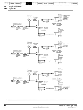
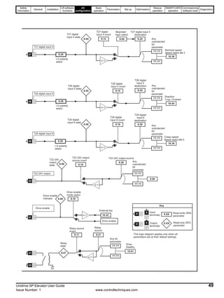
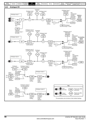
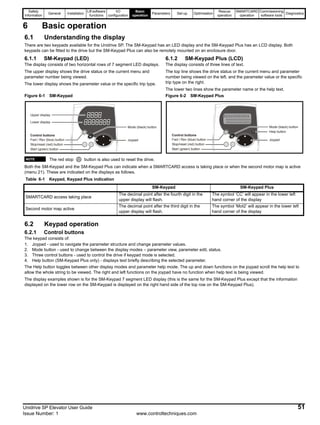
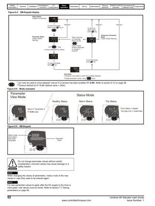
![Safety
Information
General Installation
Lift software
functions
I/O
configuration
Basic
operation
Parameters Set-up Optimisation
Rescue
operation
SMARTCARD
operation
Commissioning
software tools
Diagnostics
Unidrive SP Elevator User Guide 53
Issue Number: 1 www.controltechniques.com
6.3 SM-Keypad Plus
The following information covers the SM-Keypad Plus with alpha
numeric LCD display and additional Help feature.
The following section details displaying and adjusting the elevator drive
parameters
6.3.1 SM-Keypad and SM-Keypad Plus function
details
Figure 6-6 SM-Keypad Plus
The SM Keypad Plus LCD display is recommended for use with the SM-
ELV software with this providing help text in addition to the parameter
descriptions.
When using the SM-Keypad Plus LCD display with the SM-ELV elevator
software it is recommended that the keypad custom elevator text is
programmed into the SM-Keypad Plus LCD display. The custom elevator
text will provide detailed information on specific lift parameters on the
display which would not normally be available with the standard keypad
software.
6.4 Operation
Figure 6-7 SM-Keypad Plus display at power up
Figure 6-8 Select parameter
Mode button
change between status
and edit mode
Status mode:
Select menu
Edit mode:
Scroll right and text
Help button
Status mode:
Scroll up and down in
the selected menu
Edit mode:
Change parameter value
Reset
Status mode:
Drive status
and value
Edit mode:
Parameter
and value
Parameter
text
or helptext
NOTE
NOTE
Status Display
Initialising
Only on first power up
Only on first power up
Display
Operating mode
If the drive has tripped the display
is flashing. Refer to Chapter
13 Diagnostics
Initialising finished
Drive ready
Keypad Plus
Initialising
Ver: 01.00.00
Keypad Plus
READING DATABASE
Drive
Keypad Plus
PROGRAMMING FLASH
Drive
inh SErVO
Operating mode
trip Enc3
0.10 0.0
Motor speed
Status Mode
(Display not flashing)
Parameter Mode
(Upper display
flashing)
To enter Parameter
Mode, press key or
inh 0.0
Motor speed
0.14 800
[0] Nominal elevator
Speed in mm/s
Use * keys
to select parameter for editing
0.10 0.0
Motor speed](https://image.slidesharecdn.com/unispelevator-140613204659-phpapp02/85/Uni-sp-elevator-53-320.jpg)
![Safety
Information
General Installation
Lift software
functions
I/O
configuration
Basic
operation
Parameters Set-up Optimisation
Rescue
operation
SMARTCARD
operation
Commissioning
software tools
Diagnostics
54 Unidrive SP Elevator User Guide
www.controltechniques.com Issue Number: 1
Figure 6-9 Edit parameter Figure 6-10 Edit parameter in another Menu 0 level
6.5 Menu structure
The drive parameter structure consists of menus and parameters.
The drive initially powers up so that only menu 0 can be viewed. The up
and down arrow buttons are used to navigate between parameters and
once level 2 access (L2) has been enabled (see Pr 0.49) the left and
right buttons are used to navigate between menus. For further
information, refer to section 7.10 Parameter access level and security on
page 49.
To enter Edit Mode,
press key (Parameter
value is flashing)
To enter Edit Mode,
press key (Parameter
value is flashing)
To exit Edit Mode,
press key
To return to Status Mode
press key or after a delay
time of 240s the display returns
to Status Mode
0.14 900
[0] Nominal elevator
Speed in mm/s
Change parameter values
Using
Select a character with
key
key
0.14 800
[0] Nominal elevator
Speed in mm/s
0.14 900
[0] Nominal elevator
Speed in mm/s
0.14 900
[0] Nominal elevator
speed in mm/s
For Parameter Mode
press key or one
of the arrow keys
0.14 900
[0] Nominal elevator
Speed in mm/s
Select Pr with0.12
key
To enter Edit Mode,
press key (Parameter
value is flashing)
To enter Edit Mode,
press key (Parameter
value is flashing)
Change parameter values
Using key
0.14 900
[0] Nominal elevator
Speed in mm/s
0.14 900
[0] Nominal elevator
Speed in mm/s
0.12 1
Menu 0 Selector
0.12 0
Menu Selector
0.12 0
Menu Selector
0.14 900
[0] Nominal elevator
Speed in mm/s
To exit Edit Mode,
press key
Use * keys
to select parameter for editing
To enter Edit Mode,
press key (Parameter
value is flashing)
To enter Edit Mode,
press key (Parameter
value is flashing)
Change parameter values
Using
Select a character with
key
key
0.15 320
[1] Sheave
Diameter in mm
0.15 480
[1] Sheave
Diameter in mm
0.15 480
[1] Sheave
Diameter in mm
0.12 1
Menu 0 Selector](https://image.slidesharecdn.com/unispelevator-140613204659-phpapp02/85/Uni-sp-elevator-54-320.jpg)
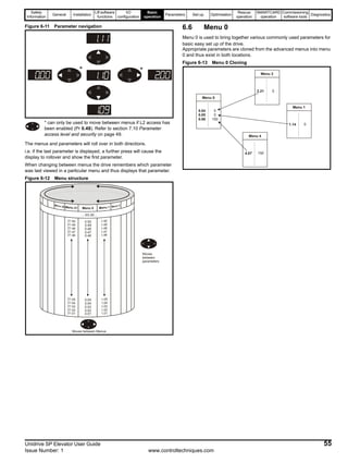
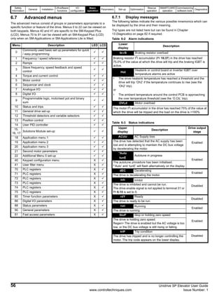
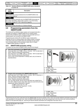
![Safety
Information
General Installation
Lift software
functions
I/O
configuration
Basic
operation
Parameters Set-up Optimisation
Rescue
operation
SMARTCARD
operation
Commissioning
software tools
Diagnostics
58 Unidrive SP Elevator User Guide
www.controltechniques.com Issue Number: 1
6.9 Changing the operating mode
Changing the operating mode returns all parameters to their default
value, including the motor parameters. (Pr 0.49 Security status and Pr
0.34 User security code are not affected by this procedure.)
Procedure
Use the following procedure only if a different operating mode is
required:
1. Ensure the drive is not enabled, i.e. terminal 31 is open or Pr 6.15 is
Off (0)
2. Enter either of the following values in Pr 0.00, as appropriate:
1253 (Europe, 50Hz AC supply frequency)
1254 (USA, 60Hz AC supply frequency)
3. Change the setting of Pr 0.48 as follows:
The figures in the second column apply when serial communications are
used.
4. Either:
• Press the red reset button
• Toggle the reset digital input
• Carry out a drive reset through serial communications by setting
Pr 10.38 to 100 (ensure that Pr. xx.00 returns to 0).
6.10 Saving parameters
When changing a parameter in Menu 0, the new value is saved when
pressing the Mode button to return to parameter view mode from
parameter edit mode.
If parameters have been changed in the advanced menus or menu 0[1],
menu 0[2], menu 0[3], menu 0[4], then the change will not be saved
automatically. A save function must be carried out.
Procedure
Enter 1000* in Pr. xx.00
Either:
• Press the red reset button
• Toggle the reset digital input
• Carry out a drive reset through serial communications by setting
Pr 10.38 to 100 (ensure that Pr. xx.00 returns to 0).
*If the drive is in the under voltage trip state or is being supplied from a
low voltage DC supply, a value of 1001 must be entered into Pr xx.00 to
perform a save function.
6.11 Restoring parameter defaults
Restoring parameter defaults by this method saves the default values in
the drive’s memory. (Pr 0.49 and Pr 0.34 are not affected by this
procedure.)
Procedure
1. Ensure the drive is not enabled, i.e. terminal 31 is open or Pr 6.15 is
Off (0)
2. Enter 1233 (EUR 50Hz settings) or 1244 (USA 60Hz settings) in
Pr xx.00.
3. Either:
• Press the red reset button
• Toggle the reset digital input
• Carry out a drive reset through serial communications by setting
Pr 10.38 to 100 (ensure that Pr. xx.00 returns to 0).
6.12 Restoring Lift software defaults
All parameters used for the Elevator software can be set back to the
default values at any stage by setting Pr 18.50 = Off.
This will automatically set the following parameters listed to their default
values and carry out a save, with all previous parameters adjustments
being over written.
6.13 Parameter access level and security
The parameter access level determines whether the user has access to
menu 0 only or to all the advanced menus (menus 1 to 21) in addition to
menu 0.
The User Security determines whether the access to the user is read
only or read write.
Both the User Security and Parameter Access Level can operate
independently of each other as shown in the table below:
RW = Read / write access RO = Read only access
The default settings of the drive are Parameter Access Level L1 and
user Security Open, i.e. read / write access to Menu 0 with the advanced
menus not visible.
6.13.1 Access level
The access level is set in Pr 0.49 and allows or prevents access to the
advanced menu parameters.
The Access Level can be changed through the keypad even if the User
Security has been set.
6.13.2 User Security
The User Security, when set, prevents write access to any of the
parameters (other than Pr. 0.49 and Pr 11.44 Access Level) in any
menu.
Setting User Security
Enter a value between 1 and 999 in Pr 0.34 and press the button;
the security code has now been set to this value. In order to activate the
security, the Access level must be set to Loc in Pr 0.49. When the drive
is reset, the security code will have been activated and the drive returns
to Access Level L1. The value of Pr 0.34 will return to 0 in order to hide
the security code. At this point, the only parameter that can be changed
by the user is the Access Level Pr 0.49.
Unlocking User Security
Select a read write parameter to be edited and press the button, the
upper display will now show CodE. Use the arrow buttons to set the
security code and press the button.
With the correct security code entered, the display will revert to the
parameter selected in edit mode.
If an incorrect security code is entered the display will revert to
parameter view mode.
To lock the User Security again, set Pr 0.49 to Loc and press the
reset button.
Disabling User Security
Unlock the previously set security code as detailed above. Set Pr 0.34 to
0 and press the button. The User Security has now been disabled,
0.48 setting Operating mode
1 Open-loop
2 Closed-loop Vector
3 Closed-loop Servo
4
Regen (See the Unidrive SP Regen
Installation Guide for more information
about operating in this mode)
Parameter
Access Level
User Security
Menu 0
status
Advanced
menus status
L1 Open RW Not visible
L1 Closed RO Not visible
L2 Open RW RW
L2 Closed RO RO
String Value Effect
L1 0 Access to menu 0 only
L2 1 Access to all menus (menu 0 to menu 21)](https://image.slidesharecdn.com/unispelevator-140613204659-phpapp02/85/Uni-sp-elevator-58-320.jpg)
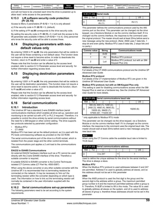
![Safety
Information
General Installation
Lift software
functions
I/O
configuration
Basic
operation
Parameters Set-up Optimisation
Rescue
operation
SMARTCARD
operation
Commissioning
software tools
Diagnostics
60 Unidrive SP Elevator User Guide
www.controltechniques.com Issue Number: 1
6.17 Setting of motor and elevator parameters
Before the initial start, the data for the winch motor and the elevator must be entered. Refer to the motor nameplate and elevator calculations.
Table 6-5 Menu 0 parameters
*The adjustment of the gear ratio and the sheave diameter is done with the nominal elevator rpm. It can be calculated as follows:
Pr 0.13[0] (Pr 18.29) [nNominal] = Pr 0.14[0] (Pr 18.30)[VNominalmm/s] * Gearing * Roping * 60 / (π * Dsheive[mm])
For Synchronous motors only the number of motor poles and the motor current is required. Do not enter the motor data that is greyed out.
For the initial test run, only the motor data and the elevator data that is listed in the examples must be adjusted. For winches with induction motors,
with or without encoders, the full motor map must be set.
Parameter Type Default
Units
Setting recommendation
Open LP Closed LP
Minimum rpm Pr 0.01 RW min-1
min-1
Maximum rpm Pr 0.02 RW ±32000 min-1 min-1
Acceleration rate Pr 0.03 RW 10.000 cm/s2
m/s2
Deceleration rate Pr 0.04 RW 10.000 cm/s2
m/s2
Current limit Pr 0.06 RW Imax / ln 0.1% ln 0.1% ln
Speed loop P-Gain Pr 0.07 RW 32000 0.1000
Speed loop I- Gain Pr 0.08 RW 32000 4.00
Motor active current Pr 0.11 RO ± Imax A A Torque producing current
Menu 0 selector Pr 0.12 RO 4 Ranges between [0], [1], [2], [3], [4]
Nominal elevator rpm * Pr 0.13 RW 4000 min-1
min-1 From Table 4.10 Nominal elevator rpm
calculation and adjustment
Nominal elevator speed Pr 0.14 RW 10000 mm/s mm/s
From Table 4.10 Nominal elevator rpm
calculation and adjustment
V1 (Creep speed) Pr 0.15 RW 10000 mm/s mm/s
V2 (Inspection) Pr 0.16 RW 10000 mm/s mm/s
V3 (Nominal 1) Pr 0.17 RW 10000 mm/s mm/s
V4 (Medium 1) Pr 0.18 RW 10000 mm/s mm/s
V5 (Re-levelling) Pr 0.19 RW 10000 mm/s mm/s
V6 (FAST speed) Pr 0.20 RW 10000 mm/s mm/s
V7 (Additional 1) Pr 0.21 RW 10000 mm/s mm/s
Stop- Deceleration Pr 0.22 RW 2000 mm/s2
mm/s2 Creep to floor only
Start- Jerk Pr 0.23 RW 10000 mm/s3
mm/s3
Run- Jerk Pr 0.24 RW 10000 mm/s3 mm/s3
Stop- Jerk Pr 0.25 RW 800 mm/s3
mm/s3 Creep to floor only
Threshold 1 Pr 0.26 RW 10000 mm/s mm/s Pr 18.32 - Setting in Pr 0.26[0] (Pr 18.21)
Threshold 2 Pr 0.27 RW 10000 mm/s mm/s Pr 18.33 - Setting in Pr 0.27[0] (Pr 18.22)
Speed selector Pr 0.28 RO 1818
Encoder lines Pr 0.29 RW 50000 PPR PPR Drive encoder input
SMARTCARD modes Pr 0.30 RW
V8 (Additional 2) Pr 0.31 RW 10000 mm/s mm/s
V9 (Additional 3) Pr 0.32 RW 10000 mm/s mm/s
V10 (Additional 4) Pr 0.33 RW 10000 mm/s mm/s
Actual speed Pr 0.34 RW ±32000 min-1
min-1
Serial comms mode Pr 0.35 RW ANSI, RTU ANSI, RTU
Serial comms baud rate Pr 0.36 RW Kb Kb
Serial address Pr 0.37 RW
Current loop P-Gain Pr 0.38 RW 32000
Current loop I- Gain Pr 0.39 RW 32000
Switching frequency Pr 0.41 RW kHz kHz
Motor poles Pr 0.42 RW 120
Power factor/
Encoder phase angle
Pr 0.43 RW
Motor voltage Pr 0.44 RW 480 V V
Nominal rpm / Thermal time
constant
Pr 0.45 RW min-1 min-1
Motor current Pr 0.46 RW ± Imax A A
Motor frequency Pr 0.47 RW 50 Hz Hz
Operating mode Pr 0.48 RW OL, VT, SV OL, VT, SV
Security status Pr 0.49 RW
L1(0), L2(1),
Loc(2)
L1(0), L2(1),
Loc(2)
Drive software version Pr 0.50 RO](https://image.slidesharecdn.com/unispelevator-140613204659-phpapp02/85/Uni-sp-elevator-60-320.jpg)
![Safety
Information
General Installation
Lift software
functions
I/O
configuration
Basic
operation
Parameters Set-up Optimisation
Rescue
operation
SMARTCARD
operation
Commissioning
software tools
Diagnostics
Unidrive SP Elevator User Guide 61
Issue Number: 1 www.controltechniques.com
7 Parameters
7.1 Security code protection
Access to Menu 0 parameters (Pr 0.12 = 1 to 4) is only allowed:
c) If the security code in Pr 20.15 = 0, (default)
d) If the setting of Pr xx.00 corresponds to the drive security code.
By setting the security code in Pr 20.15 ≠ 0, it will lock the access to the
lift parameter sets available in Menu 0 (Pr 0.12 = 1 to 4). Only personnel
who know the security code will be able to access these.
7.2 Defaults
All parameters used for the Elevator software can be set back to the
default values at any stage by setting Pr 18.50 = OFF (0).
This will automatically set the following parameters to their default
values and carry out a save, with all previous parameters adjustments
being over written.
7.3 Drive mode change
From SM-ELV software V1.10 the drive parameter settings can be saved
during a mode change from, for example; closed loop vector to open
loop, during a feedback fault.
The motor, interface and elevator parameters are stored in the non-
volatile ram in the SM-ELV module. The configuration can be completely
restored after a drive mode change provided the following procedure is
followed:
1. Pr 01.00 = 1255 (EUR) or 1256 (US) (change drive mode with
standard defaults excluding menus 15 through to 20)
2. Pr 00.48 = Set drive mode
3. Press the reset button -the drive mode change will then be executed
The following parameters are restored after drive mode change:
N
If the above sequence of setting Pr 01.00 = 1255 (EUR) or 1256 (US) is
not executed, the factory default settings will be restored to the drive
without saving the application parameter settings.
When the drive mode is changed from open loop to closed loop vector or
servo, the following parameters are restored:
Pr 4.12 = current demand filter 1
Pr 4.13 = current controller Kp gain
Pr 4.14 = current controller Ki gain
Pr xx.10 = encoder lines
Pr xx.15 = encoder type
Pr xx.13 = encoder supply voltage
Pr xx.16 = encoder termination
Pr 3.25 = encoder phase angle (only Servo mode)
Using this function the elevator can be operated without any additional
settings after a mode change back to closed loop vector or servo has
occurred.
7.4 Lift software status
To verify the Lift software is running, Pr 0.29 [0] (Pr 20.02). This should
toggle every 1s between 10614 and -10614.
7.5 Parameter sets
The following parameter sets Menu 0, 18,19, and 20 are used
specifically for the Lift software set-up, optimisation and diagnostics.
Additional parameter sets are used in the Unidrive SP to set up the
motor map, speed feedback and carrying out the auto tune, for details on
these refer to the Unidrive SP User Guide.
Menu zero can be set-up to display either the Basic parameters as
shown in Table 6-5 on page 60, or the following parameter sets can also
be displayed in Menu zero parameters (Pr 0.13 through to Pr 0.33),
Installation parameters (Pr 0.12=1), Control parameters (Pr 0.12=2),
Distance parameters (Pr 0.12=3), or Diagnostics Parameters
(Pr 0.12=4).
7.6 Menu 0 structure
Pr 0.00 to Pr 0.12 and Pr 0.38 to Pr 0.50 are fixed having a single
function.
Pr 0.13 to Pr 0.37 can have various functions / parameter sets these
being selected by the user.
Menu 0, Pr 0.12, is changed to select different parameter sets or groups
of elevator parameters. After power-up or the saving of parameters, the
standard configuration for Pr 0.13 to Pr 0.37 is loaded automatically. By
setting Pr 0.12 to the predefined code 1, 2, 3 or 4, other configurations of
Pr 0.13 to Pr 0.37 are selected as shown in the following. In this
documentation the value of Pr 0.12 is shown in square brackets after the
menu zero parameter to indicate which configuration is selected.
For example:
Pr 0.26[1] of the elevator parameters Pr 0.12 = 1:⇒ Pr 0.26 [1]
To select Pr 0.18 [2]⇒ set Pr 0.12 = 2 and select Pr 0.18
Pr 2.11 Pr 2.21 Pr 4.09 Pr 5.06 Pr 5.07 Pr 5.08 Pr 5.09
Pr 5.10 Pr 5.11 Pr 5.18 Pr 8.21 Pr 8.11 Pr 8.31 Pr 8.22
Pr 8.12 Pr 8.32 Pr 8.23 Pr 8.13 Pr 8.33 Pr 8.24 Pr 8.14
Pr 8.25 Pr 8.15 Pr 8.26 Pr 8.16 Pr 8.27 Pr 8.17 Pr 12.06
Pr 12.07 Pr 12.26 Pr 12.27 Pr 7.10 Pr 7.14 Pr 7.15 Pr 11.23
Pr 11.24 Pr 11.25 Pr 21.05 Pr 21.16 Pr 21.22 Pr 21.23 Pr 21.27
Pr 21.28 Pr 21.29 Pr 21.31
NOTE](https://image.slidesharecdn.com/unispelevator-140613204659-phpapp02/85/Uni-sp-elevator-61-320.jpg)
![Safety
Information
General Installation
Lift software
functions
I/O
configuration
Basic
operation
Parameters Set-up Optimisation
Rescue
operation
SMARTCARD
operation
Commissioning
software tools
Diagnostics
62 Unidrive SP Elevator User Guide
www.controltechniques.com Issue Number: 1
Figure 7-1 Menu 0 Structure
Figure 7-2 Logic overview - Menu 0
Menu 0 Selection
Pr 0.00
Fixed
Pr 0.00
Pr 0.11
Pr 0.13
Switched
Pr 0.14
Pr 0.37
Pr 0.38
Fixed
Pr 0.39
Pr 0.50
Basic Parameters
Pr 0.12 = 0
Installation
Parameters
Pr 0.12 = 1
Diagnostics
Parameters
Pr 0.12 = 4Pr 0.13 [0] = nB
Pr 0.14 [0] = VB
Pr 0.32 [0] = V10
Pr 0.13 [1] = VThreshold 1
Pr 0.14 [1] = VThreshold2
Pr 0.32 [1] = Ident
Pr 0.13 [2] = L1SIGMA
Pr 0.14 [2] = I-Filter
Pr 0.32 [2] = Enc.Volt
Control Parameters
Pr 0.12 = 2
Distance
Parameters
Pr 0.12 = 3
Pr 0.13 [4]
Pr 0.14 [4]
Pr 0.32 [4] = Act. rpm
Pr 0.13 [3]
Pr 0.14 [3]
Pr 0.32 [3] = D. Short L
UnidriveSP-Menu0-Structure
Menu 0 Selection
Pr 0.37
Pr 0.37
Pr 0.37
Pr 0.37
Pr 0.37
Motor magnetised
Brake release delay
Brake apply delay
7.02 7.01 8.04 8.03 8.06 Terminal state
0
0
0
0
0
1
0
0
0
0
1
x
0
0
0
1
x
x
0
0
1
x
x
x
0
1
x
x
x
x
v = 0
0.15 creep speed
0.16 inspection
0.17 Vnom 1
0.18 Vmed 1
0.19 Vrelevel
T.7 T.5 T.27 T.26 T.29
Terminal polarity
positive logic
Pr 8.29 = 1
Pr 0.13
Pr 0.14
Nominal
lift rpm
Nominal
lift speed
Pr 0.23
Pr 0.03
Pr 0.24
Pr 0.04
Pr 0.22
Deceleration
Stop jerk
Acceleration
Start jerk
Run jerk
Stop deceleration
Pr 3.03
Pr 0.10
+
_
Pr 0.07
Pr 0.08
Pr 0.09
P gain speed
I gain speed
D gain speed
Pr 0.06
Current
limit
Pr 4.12
Current
filter
Pr 0.11 Active
currentSpeed error threshold
Distance error threshold
Pr 0.29
Encoder
lines
Encoder
Motor
3 - phase
Pr 0.41
Pr 0.42
Pr 0.43
Switching kHz
Motor poles
Power factor
Pr 0.44
Pr 0.45
Pr 0.46
Motor volts
Motor rpm
Motor amps
Pr 0.47 Motor Hz
Pr 0.26
v - Threshold 1
T.24
Advanced
door
opening
T.25
Pr 0.25 [1]
Pr 0.24 [1]
Brake output
T.25 function
select Current
feedback
Pr 0.23 [1]
Pr 0.29[4]
Pr 0.26[4]
Variable Gains
Start
Travel
Positioning
Start
Travel
Pr 0.21[1] (Pr 18.48)
(Pr 19.48)
Trip 70
Trip 71
Trip 77
Motor phase loss
detection
Pr 0.24
Run jerk
Pr 0.24 Run jerk
Pr 0.24Run jerk
Pr 0.25
Trip 76
Motor magnetised
detection
Pr 0.19[4] (Pr 18.31)
Pr 0.18[4] (Pr 18.43)](https://image.slidesharecdn.com/unispelevator-140613204659-phpapp02/85/Uni-sp-elevator-62-320.jpg)
![Safety
Information
General Installation
Lift software
functions
I/O
configuration
Basic
operation
Parameters Set-up Optimisation
Rescue
operation
SMARTCARD
operation
Commissioning
software tools
Diagnostics
Unidrive SP Elevator User Guide 63
Issue Number: 1 www.controltechniques.com
7.6.1 Installation parameters - Pr 0.12 = 1
Parameter Description Type Range Default Units Notes
0.13 [1]
Calculated nominal
elevator rpm
RO 32000 1/min
Calculated in software (refer to section
4.10 Nominal elevator rpm calculation and
adjustment )
0.14 [1] Roping RW 4 1 1 : 1 (1), 2 : 1 (2), 3 : 1 (3)
0.15 [1] Sheave diameter RW 32767 480 mm
0.16 [1] Gear ratio numerator RW 32767 31
0.17 [1] Gear ratio denominator RW 32767 1
0.18 [1] Speed for start optimiser RW 10000 10 mm/s
Refer to section0.19 [1] Time for start optimiser RW 10000 300 ms
0.20 [1] Jerk for start optimiser RW 10000 10 mm/s3
0.21 [1] Reference selector type RW OFF (0) or On (1) OFF (0)
OFF (0) = Binary selection, On (1) = Priority
selection
0.22 [1] Invert direction RW OFF (0) or On (1) OFF (0)
0.23 [1] Function T. 25 RW 20.50 18.31 Pr 18.31: Brake / Pr 18.43: Motor flux
0.24 [1] Brake release delay RW 32000 1000 ms
0.25 [1] Brake apply delay RW 32000 1000 ms
0.26 [1] Motor contactor delay RO 32000 0 ms Short (reduce) / Long (increase)
0.27 [1] Enable peak curve RW Bit OFF (0) or On (1) OFF (0)
On (1): Peak curve enable, OFF (0): peak curve
disabled
0.28 [1] Software Version RO SM-ELV software version
0.29 [1] Identity number RO ±10614 Changes sign every 1 second “healthy”
0.30 [1]
SMARTCARD parameter
cloning
RW SMARTCARD operation
0.31 [1] Encoder slot RW Drive / Slot Drive Pr 3.26, configure for drive or Solutions Module
0.32 [1] Single turn comms bit RW 0 - 32 bits Pr 3.35, single turn encoder bits
0.33 [1] Encoder voltage RW 5, 8, 15 5 Vdc Pr 3.36, encoder supply voltage
0.34 [1] Encoder type RW Pr 3.38, encoder type
0.35 [1] Encoder error detection RO 0 - 7 1 Pr 3.40, error detection for drive encoder input
0.36 [1]
Auto configuration/ ssi
binary/gray
RO OFF (0) or On (1) OFF (0)
Pr 3.41, comms encoder auto-configuration or SSI
code
0.37 [1]
Automatic motor nominal
rpm
RW OFF (0) or On (1) OFF (0)
0.38 [1] Rapid stop RW OFF (0) or On (1) OFF (0) Pr 19.49, enable for rapid stop
0.39 [1] Rapid stop deceleration RW 10.000 2.000 m/s2 Pr 21.05, deceleration rate for rapid stop](https://image.slidesharecdn.com/unispelevator-140613204659-phpapp02/85/Uni-sp-elevator-63-320.jpg)
![Safety
Information
General Installation
Lift software
functions
I/O
configuration
Basic
operation
Parameters Set-up Optimisation
Rescue
operation
SMARTCARD
operation
Commissioning
software tools
Diagnostics
64 Unidrive SP Elevator User Guide
www.controltechniques.com Issue Number: 1
7.6.2 Control parameters - Pr 0.12 = 2
Parameter Description Type Range Default Units Notes
0.13 [2] Current demand filter 1 RW 250 0.0 ms Refer to section 4.11 Variable Gains - selection /
optimisation0.14 [2] Current demand filter 2 R/W 250 0.0 ms
0.15 [2] Current demand filter setup R/W OFF (0) or On (1) OFF (0) OFF (0) at start only, On (1) constant
0.16 [2] Current loop Kp- gain start R/W 32767
0.17 [2] Current loop Ki- gain start R/W 32767
0.18 [2] Optimise rated speed RW OFF (0) or On (1) On (1) Enable, Pr 5.16 in Unidrive SP
0.19 [2] P- gain start locking RW 1000 0 Refer to section 4.11 Variable Gains - selection /
optimisation0.20 [2] D- gain start locking RW 30000 0
0.21 [2]
Variable speed loop gain
enable
RW OFF (0) or On (1) OFF (0)
1: Separate speed controller gains for start and run
only (Refer to section 4.11 Variable Gains - selection
/ optimisation )
0.22 [2]
Speed loop gain transition
time
RW 32000 500 ms
Refer to section 4.11 Variable Gains - selection /
optimisation
0.23 [2] Speed loop Kp - gain run RW 32767 50
0.24 [2] Speed loop Ki - gain run RW 32767 80
0.25 [2] Speed loop Kp - gain start RW 32767 50
0.26 [2] Speed loop Ki - gain start RW 32767 80
0.27 [2]
Inertia compensation
scaling
RW 32767 1000
0.28 [2] Inertia compensation RW OFF (0) or On (1) OFF (0) Enable (refer to section 4.16.2)
0.29 [2]
Motor magnetised
threshold.
RW 990 200 0,1%
0.30 [2]
Encoder supply voltage /
resolver excitation
RW 0 - 2 0
0 = 5V , 1 = 8V, 2 = 15V
Resolver: 0 = 3:1 , 1 or 2 = 2:1
0.31 [2] Speed loop Kp RW 32767
Refer to section 4.11 Variable Gains - selection /
optimisation
0.32 [2] Speed loop Ki RW 32767
0.33 [2] Current loop filter RW 25.0 ms
0.34 [2] Current loop Kp RW 32767
0.35 [2] Current loop Ki RW 32767
0.36 [2]
0.37 [2]](https://image.slidesharecdn.com/unispelevator-140613204659-phpapp02/85/Uni-sp-elevator-64-320.jpg)
![Safety
Information
General Installation
Lift software
functions
I/O
configuration
Basic
operation
Parameters Set-up Optimisation
Rescue
operation
SMARTCARD
operation
Commissioning
software tools
Diagnostics
Unidrive SP Elevator User Guide 65
Issue Number: 1 www.controltechniques.com
7.6.3 Distance Parameters - Pr 0.12 = 3
Parameter Description Type Range Default Units Notes
0.13 [3] Creep distance measurement RO 32000 0 mm
0.14 [3]
Calculated deceleration
distance
RO 32000 266 mm
Calculated distance - actual speed to
V1 creep speed
0.15 [3] Measured deceleration distance RO 32000 0 mm
Measured distance - actual speed to V1
creep speed
0.16 [3] Direct-to-floor sensor source RW 4 0
1 – 3: Source = Analogue input 1 – 3 / 4
4: Controlling
0.17 [3] Enable Floor sensor correction RW OFF (0) or On (1) OFF (0)
1 = Floor sensor correction
0 = No floor sensor correction
0.18 [3] Not used
0.19 [3] Floor sensor correction source RW 4 0
1: T.5, 2: T.7, 3: T.8, 4: Controlled stop
distance
0.20 [3] Floor sensor target distance RW 10000 0 mm
0.21 [3] Remaining floor sensor distance RO 32000 0 mm
0.22 [3] Speed at floor sensor activation RO 10000 0 mm/s
0.23 [3]
Time from floor sensor activation
to stop
RO 32000 0 ms
0.24 [3] P-gain following error regulation RW 32767 0 Recommended values 2...10
0.25 [3]
Following error direct-to-floor
regulation
RO 30000 75 mm
0.26 [3] Short distance landing RW 10000 0 mm
0.27 [3] Set-point peak curve distance RO 32000 0 mm
0.28 [3] Measured peak curve distance RO 32000 0 mm
0.29 [3] Stopping distance RO 32000 0 mm
Deceleration distance - creep speed to
stop
0.30 [3] Not used
0.31 [3] Deceleration distance V2 RW 26.600 s / 1000 rpm
0.32 [3] Deceleration distance V3 RW 73.800 s / 1000 rpm
0.33 [3] Deceleration distance V4 RW 3.400 s / 1000 rpm
0.34 [3] Deceleration distance V5 RW 3.400 s / 1000 rpm
0.35 [3] Deceleration distance V6 RW 3.400 s / 1000 rpm
0.36 [3] Deceleration distance V7 RW 3.400 s / 1000 rpm
0.37 [3] Deceleration distance V8 RW 0.000 s / 1000 rpm
0.38 [3] Current controller Kp RW 75
0.39 [3] Current controller Ki RW 1000
0.51 [3] Deceleration distance V9 RW 0.000 s / 1000 rpm
0.52 [3] Deceleration distance V10 RW 0.000 s / 1000 rpm](https://image.slidesharecdn.com/unispelevator-140613204659-phpapp02/85/Uni-sp-elevator-65-320.jpg)
![Safety
Information
General Installation
Lift software
functions
I/O
configuration
Basic
operation
Parameters Set-up Optimisation
Rescue
operation
SMARTCARD
operation
Commissioning
software tools
Diagnostics
66 Unidrive SP Elevator User Guide
www.controltechniques.com Issue Number: 1
7.6.4 Diagnostic parameters - Pr 0.12 = 4
Parameter Description Type Range Default Units Notes
0.13 [4] Zero speed threshold RW 250 5 rpm
0.14 [4] Not used
0.15 [4] Motor voltage at output RO 800 0 V
0.16 [4] Final speed reference RO ± 32768 0.0 mm/s (Pr 3.01 in Unidrive SP)
0.17 [4] Maximum overload RO 400.0 %In
0.18 [4] Motor magnetised RO OFF (0) or On (1) OFF (0) 1: Motor magnetised
0.19 [4] Brake output RO OFF (0) or On (1) OFF (0) ON: Brake released / OFF: Brake applied
0.20 [4] Last trip RO
0.21 [4] Previous trip RO
0.22 [4] Speed controller output RO 400.0 0.0 %In
0.23 [4] Terminal status RO 11111 T. 24/ 25/ 41/ 28/ 31 (See section 13.2.4 )
0.24 [4] Terminal status RO 11111 T. 29/ 26/ 27/ 5/ 7 (See section 13.2.4 )
0.25 [4] Speed error RO 10000 0 mm/s As Unidrive SP (Pr 3.03)
0.26 [4]
Maximum speed error
threshold
RW 10000 200 mm/s Setting = 10 x Pr 0.25[4] > 200 (Trip 70)
0.27 [4] Distance error RO 10000 0 mm
0.28 [4]
Maximum distance error
threshold
RW 10000 200 mm Setting = 10 x Pr 0.27[4] > 200 (Trip 71)
0.29 [4] Speed error RO ± 32768 0.0 rpm Speed error (Pr 3.03)
0.30 [4]
Drive encoder speed
feedback
RO ± 32768 0.0 rpm Drive encoder speed feedback (Pr 3.27)
0.31 [4]
SMARTCARD data
previously loaded
RO
0.32 [4]
SMARTCARD data
number
RO
0.33 [4]
SMARTCARD data type
/ mode
RO
0.34 [4]
SMARTCARD data
checksum
RO 0](https://image.slidesharecdn.com/unispelevator-140613204659-phpapp02/85/Uni-sp-elevator-66-320.jpg)
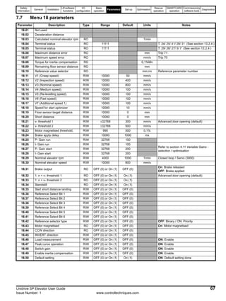
![Safety
Information
General Installation
Lift software
functions
I/O
configuration
Basic
operation
Parameters Set-up Optimisation
Rescue
operation
SMARTCARD
operation
Commissioning
software tools
Diagnostics
68 Unidrive SP Elevator User Guide
www.controltechniques.com Issue Number: 1
7.8 Menu 19 parameters
Parameter Description Type Range Default Units Notes
19.01 Speed setpoint RO ±32000 mm/s
19.02 Actual speed RO ±32000 mm/s
19.03 Ramp speed RO ±32000 mm/s
19.04 Reference acceleration RO ±32000 mm/s2
19.05 Stopping distance RO ±32000 mm
19.06 Set-point peak curve distance RO ±32000 mm
19.07 Measured peak curve distance RO ±32000 mm
19.08 Calculated deceleration distance RO ±32000 mm
19.09 Speed at floor sensor active RO ±32000 mm/s
19.10 Measured deceleration distance RO ±32000 mm
19.11 Gain transition time R/W 32768 500 ms Start to travel gains only
19.12 D-Gain position controller (start) R/W 32768 0
19.13 Stop deceleration R/W 2000 1000 mm/s2 Creep to floor only
19.14 Start jerk R/W 10000 500 mm/s3
19.15 Run jerk R/W 10000 1000 mm/s3
19.16 Stop jerk R/W 10000 800 mm/s3 Creep to floor only
19.17 Jerk for start optimiser R/W 10000 10 mm/s3
19.18 Maximum distance error threshold R/W 10000 100 mm Trip 71
19.19 Feedforward acceleration scaling R/W 32768 1000 0,1%
19.20 P-Gain position controller (start) R/W 1000 0 Position controller for start
19.21 Load measurement scaling R/W ±32768 1000 0,1%
19.22 Offset load measurement R/W ±32768 0 0,3125 mV
19.23
Filter time constant. Load
measurement
R/W ±32768 100 ms
19.24 Maximum speed error threshold R/W 1000 100 mm/s Trip 70
19.25 Brake release delay R/W 10000 1000 ms Pr 0.24 [1]
19.26 Direction inputs R/W 1 0 1 = 2 direction inputs
19.27 Gear ratio denominator R/W 32768 1
19.28 Time for start optimiser R/W 10000 300 ms
19.29 Sheave Diameter R/W 32768 480 mm
19.30 Gear Ratio numerator R/W 32768 31
19.31 Automatic motor nominal rpm R/W OFF (0) or On (1) OFF (0)
19.32 Motor contactor output R/W OFF (0) or On (1) OFF (0)
19.34 Enable current filter (start) R/W OFF (0) or On (1) OFF (0)
Refer to section 4.11
Pr 4.12 = 0 / constant
19.35 Thermistor display RO OFF (0) or On (1) OFF (0)
19.36 Overload Output RO OFF (0) or On (1) OFF (0) 1 = Overload
19.37 Load direction (last measured) RO OFF (0) or On (1) On (1)
0 = Up
1 = Down
19.38 Emergency rescue status R/W OFF (0) or On (1) OFF (0)
19.39 Emergency rescue invert R/W OFF (0) or On (1) OFF (0)
19.41 Reference Select Bit 7 R/W OFF (0) or On (1) OFF (0)
19.42 Floor sensor correction enable R/W OFF (0) or On (1) OFF (0) Refer to section 4.5
19.43 Enable motor phase loss detection R/W OFF (0) or On (1) OFF (0)
19.44 CW direction R/W OFF (0) or On (1) OFF (0)
19.48 Enable multiple gains R/W OFF (0) or On (1) OFF (0) Refer to section 4.11
19.49 Enable fast stop R/W OFF (0) or On (1) OFF (0)
19.50 Global warning RO OFF (0) or On (1) OFF (0) Displays errors during travel](https://image.slidesharecdn.com/unispelevator-140613204659-phpapp02/85/Uni-sp-elevator-68-320.jpg)
![Safety
Information
General Installation
Lift software
functions
I/O
configuration
Basic
operation
Parameters Set-up Optimisation
Rescue
operation
SMARTCARD
operation
Commissioning
software tools
Diagnostics
Unidrive SP Elevator User Guide 69
Issue Number: 1 www.controltechniques.com
7.9 Menu 20 parameters
7.10 Menu 21 parameters
N
Pr 20.25 through to Pr 20.28 and Pr 21.16, Pr 21.22, Pr 21.23 these
parameters are RO until the variable gains are selected through
Pr 0.21[2] (Pr 18.48) and Pr 19.48 = On, only then do they become R/W
allowing the user to adjust.
Parameter Description Type Range Default Units Notes
20.01 SM-ELV software version RO
20.02 Software identity number RO ±10614 10614
20.03 Serial comms status word R/W ±10615 0
20.04 Serial comms control word R/W ±10616 0
20.05 Time from floor sensor active RO 0 ms
20.06 Motor Time Constant RO 0 ms
20.07 Motor Flux Level RO 0 0,1A
20.08 Time for Load measurement R/W ±10000 200 ms
20.09 Maximum overload RO 3 % Mn
20.10 Roping R/W 4 1 1 = 1:1, 2 = 2:1, 3 = 3:1, 4 = 4:1
20.11 Program status RO 0
20.12 Creep speed parameter number R/W ±32768 0
20.13 Direct-to-Floor Sensor Source R/W 0...4 0
1: Latching
2: Momentary.
20.14 Floor sensor correction source R/W 0...4 0
1: T.5 / 2: T.7 / 3: T.8 /
4: controlled stop distance
20.15 Menu 0 Access Code R/W ±32768 0
0 = No security code active
> 0 Access to Pr 0.00...Pr 0.50
20.16 Menu 0 Select R/W 0...4 0
Switch of configuration Pr 0.13 -
Pr 0.30 (See section 7.5)
20.17 P-Gain following error regulation R/W 32768 0
20.18 Overload Threshold R/W ±32768 120 %
Load in % of nominal torque (Mn)
20.19 Load measurement value RO 0 %
20.20 Motor contactor delay RO 0 ms Short (reduce), Long (increase)
20.21 Creep Distance RO 0 mm Measured every run
20.22 V8 (Additional speed 2) R/W 50 mm/s
20.23 V9 (Additional speed 3) R/W 400 mm/s
20.24 V10 (Additional speed 4) R/W 800 mm/s
20.25 Current loop Kp start R/W 30000 150
Refer to section 4.11
20.26 Current loop Ki start R/W 30000 2000
20.27 Speed loop Kp positioning (stop) R/W 30000 100
20.28 Speed loop Ki positioning (stop) R/W 30000 100
20.29
Variable gains speed threshold
deceleration
R/W 3000 100 mm/s
20.30 Variable gains deceleration time R/W 3000 0 ms
20.31 UPS maximum power R/W 3001 W
Parameter Description Type Range Default Units Notes
21.05 Rapid stop rate R/W 10.000 2.000 m/s2 Enabled with Pr 19.49 = 1
21.16 Current filter positioning (stop) R/W 25.0 0.0 ms
Refer to section 4.1121.22 Current loop Kp positioning (stop) R/W 30000 150
21.23 Current loop Ki positioning (stop) R/W 30000 2000
21.28 Evacuation current limit full load R/W 30000 80 %
Only if Pr 19.38 = On
21.29 Evacuation current limit no load R/W 30000 120 %
4.23 Current filter start R/W 25.0 0.0 ms Refer to section 4.11
NOTE](https://image.slidesharecdn.com/unispelevator-140613204659-phpapp02/85/Uni-sp-elevator-69-320.jpg)
![Safety
Information
General Installation
Lift software
functions
I/O
configuration
Basic
operation
Parameters Set-up Optimisation
Rescue
operation
SMARTCARD
operation
Commissioning
software tools
Diagnostics
70 Unidrive SP Elevator User Guide
www.controltechniques.com Issue Number: 1
8 Set-up
For set-up of the elevator, follow the next section and also refer to
Chapter 12 Commissioning software tools on page 81
Table 8-1 Initial set-up
For the initial set-up of an elevator adjustment of the control loops for the
motor control must be carried out. This is performed by the drive through
automatic self-tuning, Auto-tune. During the Auto-tune the elevator must
be operated manually, therefore the inspection command has to be
provided.
If inspection is active and the drive is not enabled or motor does not run,
please refer to Setting of terminal functions.
8.1 Open loop vector - Autotune
Measurement of motor stator parameters
For the Open Loop vector control mode it is necessary to measure the
stator resistance and voltage offset which can automatically be carried
out by the drive at the start of the motor through a Static Auto-tune
Pr 0.40 = 1
To measure the stator resistance and voltage offset
• Pr 0.40 = 1 - start Static Auto-tune.
• Wait until Pr 0.40 = 0 then stop inspection run.
• Save parameters.
8.2 Closed loop vector - Autotune
Static autotune
This measurement is very convenient, because it is performed at
standstill with the brake applied. For optimisation of the elevator the
drive measures both the stator resistance Pr 5.17 and the transient
inductance Pr 5.24.
• Pr 0.40 = 1 - start inspection speed.
• Wait until Pr 0.40 = 0 then stop inspection speed.
Note setting of Pr 5.17 / Pr 5.24
• Save parameters.
Automatic current controller autotune
This measurement is very convenient, because it is also performed at
standstill with the brake applied. Setting Pr 0.40 = 4 sets up both the
integral Pr 0.39 (Pr 4.14) and proportional Pr 0.38 (Pr 4.13) current loop
gains.
• Pr 0.40 = 4 - start static current controller gain set-up
• Pr 0.38, Pr 0.39 are changed at start -stop Inspection run
Autotune and motor characteristic measurement
For complete optimisation the drive can measure in addition to the
current loop gain setup and stator resistance and stator inductance the
motor characteristics.
During this test it is necessary to remove the ropes from the sheave due
to the motor having to run for several seconds.
• Pr 0.40 = 2 - start inspection speed
• Wait until Pr 0.40 = 0 then stop inspection speed
Autotune of rated motor speed
Additional optimisation of the drive and motor can be applied through the
rated speed Auto-tune which will setup the correct slip, this should be
done with greater then 5/8 load present and at a speed greater than
rated frequency/8
During this test it is necessary to remove the ropes from the sheave due
to the motor having to run for several seconds.
Activate automatic speed optimiser
Initial Configuration and Setup procedure
Before power up
Motor connections
Make motor connections and ensure these are correct
orientation for closed loop operation (Unidrive SP).
Brake connections & configuration
Connect brake control connections (Unidrive SP or Elevator
controller).
Motor contactor connections &
configuration
Connect motor contactor control connections (Unidrive SP or
Elevator controller).
Encoder feedback connections
Connect encoder feedback ensuring correct cable is used and
screening / earthing recommendations are followed (See
Chapter 3 Installation ).
Encoder output connections
Fit option module to provide simulated encoder output when
operating in closed loop mode.
Control connections
Make all connections from Elevator controller to Unidrive SP,
following control connections (See Chapter 3 Installation ).
Power up
Parameter configuration Control connections
Ensure all control connections required for elevator speed
selection are configured, along with brake control and motor
contactor control if required (See Chapter 5 I/O configuration ).
Motor Set-up all motor related parameter
Encoder feedback
Set-up encoder feedback connected to drive along with
simulated encoder output if required for Elevator controller.
Elevator parameters
Set-up elevator parameters for SM-ELV option module (See
section 4.10 Nominal elevator rpm calculation and adjustment ).
Auto-tune An auto-tune should be carried out to set-up the drive to the
motor (asynchronous [Open loop and Closed loop vector] or
synchronous [Servo])
• Voltage Offset [OL]
• Power Factor [OL CL]
• Stator Resistance [OL CL SV]
• Transient Inductance [OL CL SV]
• Stator Inductance [CL]
• Phase offset [SV]](https://image.slidesharecdn.com/unispelevator-140613204659-phpapp02/85/Uni-sp-elevator-70-320.jpg)
![Safety
Information
General Installation
Lift software
functions
I/O
configuration
Basic
operation
Parameters Set-up Optimisation
Rescue
operation
SMARTCARD
operation
Commissioning
software tools
Diagnostics
Unidrive SP Elevator User Guide 71
Issue Number: 1 www.controltechniques.com
• Pr 0.18[2] = 1 and Save parameters
Note setting of Pr 5.08
• Save parameters
8.3 Servo - Autotune
The phase angle of magnetic rotor flux relative to the rotor's feedback
device angular orientation must be measured, or if given on the motor's
nameplate information, must be entered into a drive parameter.
Manual setting of the phase angle parameter for
known winches
If the value is known and the connection of the motor phases is U - V - W
at the drive, proceed as follows:
• Setting the phase angle
• Set Pr 0.43 = Offset and save parameter
Automatic measurement of the phase angle
If the Offset is not known or the connection of the motor phases is not U
- V - W, the value can be measured automatically by the drive at low
speed. To get exact values it is necessary to have no load at the motor
shaft and remove the ropes from the sheave. If there is low friction it may
be sufficient to have a balanced load in the car.
• Activate phasing test
• Pr 0.40 = 2, start inspection speed and maintain
• The motor will turn slowly for about 30 seconds.
• Wait until Pr 0.40 = 0 then stop inspection speed
• If a trip ENC1 occurs
• Swap motor cables U with V at the drive
• Check the offset in Pr 0.43
• This must have changed, if not, check motor contactor
Autotune - Current Loop - Motor resistance /
inductance parameters
• This measurement is very convenient, because this is performed at
standstill with the brake applied. Setting Pr 0.40 will set up both the
integral Pr 0.39 (Pr 4.14) and proportional Pr 0.38 (Pr 4.13) current
loop gains and for optimal performance the elevator drive also
measures the stator resistance Pr 5.17 and the transient inductance
Pr 5.24.
• Starting measurement
• Pr 0.40 - start inspection speed and maintain.
• The motor will turn slowly for about 30 seconds
• Wait until Pr 0.40 = 0 then stop inspection speed
• Note setting of parameters
• Save parameters
8.4 First start with empty car
Activate the first start:
• Make sure, that Enable (Terminal 31) is connected and Active
current is displayed in Pr 0.11
• Start Inspection and check the Active current display and the shaft
rotation
• If status display doesn't change to "run"
• Check logic polarity, terminals and motor conductors
If the motor Active current Pr 0.11 = 0.00
• Check logic polarity, terminals and motor conductors
If following an error trip (Trip 70 or Trip 71)
• Check motor connections and phase angle
If the motor shaft does not turn
• Check setpoint selection Pr 0.28[0] (run command applied)
If Pr 0.28[0] = 1810 instead of 1812:
• Check terminal functions and terminal state
If Trip It.AC occurs
• Check load balance, phase angle and motor connection
If motor turns shortly / stops with current
• Check pole count Pr 0.42 and encoder lines Pr 0.29
If motor turns opposite direction
• Set: Pr 0.22[1] (Pr 18.45) = 1
For closed loop vector / servo and poor motor running
• Check encoder, cable connection and screening
Other trips
• See Chapter 13 Diagnostics
If no trip
• Continue with adjustment of speed loop gains
Adjustment of the speed loop (closed loop vector and servo
only)
With recommended gain values (→ 3) only a few adjustments will be
necessary
Adjustment of the speed loop P-Gain
• Increase Pr 0.07 in steps of 0.01 until noisy or unstable
If it produces continuous noise
• Increase current filter Pr 0.14[2] from 0 to 1...max. 3 (ms)
If unstable
• Reduce Pr 0.07 to 60% of the instability value
Adjustment of speed loop I- Gain
• Increase Pr 0.08 to 20...50% of 100 * Pr 0.07
Adjustment of slip compensation (open loop only)
Reduction of V2 Inspection to V1
• Set Pr 0.16 = Pr 0.15
Enable slip compensation
• Set Pr 5.27 = 1
Start inspection "UP" and "DOWN"
• Measure speed manually with tachometer
"UP" = "DOWN"
If speed "UP" > "DOWN"
• Reduce Pr 0.45 in steps of 1...10
If speed "UP" < "DOWN"
• Increase Pr 0.45 in steps of 1...10
Motor contactor delay adjustment
To prevent over voltages at the motor windings during motor conductor
opening, the drive output should be disabled after the brake apply time is
completed. The delay between the drive output disable and the opening
of the motor conductors is displayed in Pr 0.26[1] (Pr 20.20) in ms. A
negative value indicates that the motor contactor opened under current
flow, which should be prevented. In this case the brake apply time, Pr
18.24, must be increased, at least, to the value of Pr 0.26[1] (Pr 20.20).
• Start normal floor level runs
• Check the measured conductor delay in Pr 0.26[1] in ms
• Increase Pr 0.25[1] in ms if a negative values is in Pr 0.26[1]
• Positive values of 50...100 ms in Pr 0.26[1] are acceptable.
Adjust deceleration distances:
Check speed selection Pr 18.10 reference value selected
• If not correct, check connections
Check stopping distance V1 Pr 19.05
• Change V1 (creep speed) Pr 0.15(Pr 18.11) or stop jerk level Pr 0.25
(Pr 19.16)
Check deceleration distance Pr 19.08
• Select speed for deceleration distance via inputs
• Read selected speed in Pr 18.10
• Read calculated distance in Pr 19.08
• Change Speed, deceleration Pr 0.04 or Run / jerk Pr 0.24
Start normal floor levelling runs
• Check the creep distance in Pr 20.21 in mm](https://image.slidesharecdn.com/unispelevator-140613204659-phpapp02/85/Uni-sp-elevator-71-320.jpg)
![Safety
Information
General Installation
Lift software
functions
I/O
configuration
Basic
operation
Parameters Set-up Optimisation
Rescue
operation
SMARTCARD
operation
Commissioning
software tools
Diagnostics
72 Unidrive SP Elevator User Guide
www.controltechniques.com Issue Number: 1
Figure 8-1 Deceleration and stopping distances
Pr 0.14 [3] (Pr 19.08 )
Deceleration distance
Stopping distance
Pr 0.29 [2] (Pr 19.05 )
Pr 0.16 … Pr 0.21[0]
Pr 18.12 … Pr 18.17
Operational speeds
Pr 0.15 [0] (Pr 18.11 )
Creep speed](https://image.slidesharecdn.com/unispelevator-140613204659-phpapp02/85/Uni-sp-elevator-72-320.jpg)
![Safety
Information
General Installation
Lift software
functions
I/O
configuration
Basic
operation
Parameters Set-up Optimisation
Rescue
operation
SMARTCARD
operation
Commissioning
software tools
Diagnostics
Unidrive SP Elevator User Guide 73
Issue Number: 1 www.controltechniques.com
9 Optimisation
9.1 Open loop vector
Optimise start
Due to limitations with the open loop control, torque generated at zero
speed, the timing of the profile and the brake control are essential and
therefore have to be adjusted precisely. Furthermore the motor model has
to be optimally configured for stator resistance and slip compensation
(autotune should be carried out and all motor related parameters setup as
accurately as possible).
Jerk at start too high
• Reduce start jerk Pr 0.23 ...300 mm/s3
(softer)
and/ or
• Adjust brake release delay Pr 0.24[1] in ms (500)
• Adjust speed for start optimiser Pr 0.20[1] e.g.: 10 mm/s
• Adjust time for start optimiser Pr 0.19[1] in ms (1000)
• Adjust jerk for start optimiser Pr 0.20[1] e.g.: 50mm/s3
Jerk or backward rotation when brake releases
• Increase speed for start optimiser Pr 0.20[1] e.g 50mm/s3
• Correct the value of stator resistance Pr 5.17 in Ω
Optimise constant speed
Vibrations or overshoot present
• Reduce slip compensation by increasing Pr 5.08
• Disable Quasi-square-modulation with Pr 5.20 = 0
Optimise stop
High jerk as the elevator stops
• Reduce stop jerk Pr 0.25 ...500 mm/s3
(softer)
• Reduce zero speed threshold Pr 3.05 = 0,5 ... 2 Hz
Figure 9-1 Open loop vector profile optimisation
Brake
Pr 0.23 [0] (Pr 19.14)
Pr 0.03 [0] (Pr 2.11)
Pr 0.24 [0] (Pr 19.15)
Pr 0.22 [0] (Pr 19.13)
Pr 0.25 [0] (Pr 19.16)
Pr 0.15 [0] (Pr 18.11)
Pr 0.04 [0] (Pr 2.21)Pr 0.16 … Pr 0.21[0]
Pr 18.12 … Pr 18.17
V:
Pr 0.20 [1] (Pr 19.17)
Pr 0.19 [1] (Pr 19.28)
Pr 0.18 [1] (Pr 18.18)
Operational speeds
Creep speed
Run jerk
Stop jerk
Acceleration
Start jerk
Pr 0.24 [0] (Pr 19.15)
Run jerk
Deceleration
Pr 0.24 [0] (Pr 19.15)
Run jerk
Stop decelerationStart optimisation jerk
Time for start
optimisation
Speed for start
optimisation](https://image.slidesharecdn.com/unispelevator-140613204659-phpapp02/85/Uni-sp-elevator-73-320.jpg)
![Safety
Information
General Installation
Lift software
functions
I/O
configuration
Basic
operation
Parameters Set-up Optimisation
Rescue
operation
SMARTCARD
operation
Commissioning
software tools
Diagnostics
74 Unidrive SP Elevator User Guide
www.controltechniques.com Issue Number: 1
9.2 Closed loop vector and servo
During this step the elevator performance is optimised to ensure the
travel speed is correct and comfort level is achieved. The designed
speeds and accelerations have to be achieved. In addition to the
subjective test of the elevator performance.
It is advisable to use the oscilloscope function included in the PC based
software to achieve the best performance and to prevent any issues
being overlooked. This oscilloscope will allow all associated drives
parameters to be monitored.
Optimise start
If car lurches at start
• Increase brake release delay Pr 0.24[1] to 2500ms
If motor lurches or rotates uncontrolled
• Activate separate start speed controller Pr 0.21[2]
Brake release (Pr 18.48) = 1
• P-Gain start controller Pr 0.25[1] = 2 x Pr 0.23[1] (harder)
• I-Gain start controller Pr 0.26[1] =2 x Pr 0.24[1] (stiffer)
and / or
Enable P-gain position Control: Pr 0.19[2] (Pr 19.20) = 3 to 30
Enable D-gain position Control: Pr 0.20[2] (Pr 19.12) = 10 to 100
If jerk is to high at start of profile (ramp)
• Reduce start jerk Pr 0.23...300 mm/s3 (softer)
and / or
• Activate start optimiser by setting Pr 18.18 > 0
• Set Speed for start optimiser Pr 0.18[1] e.g.: 10 mm/s
• Set time for start optimiser Pr 0.19[1] e.g.: 800...1000 ms
• Set jerk for start optimiser Pr 0.20[1] e.g.: 10...20 mm/s3
Check elevator starts
• If OK, reduce brake release delay as follows
Adjustment of brake release delay
• Reduce Pr 0.24[1] to 300ms as long as no lurch at start
Optimise constant speed
Vibration of gearless motors
• Increase I- gain of the current controller Pr 0.38 (max. 10000)
• Increase P- gain of the current controller Pr 0.39 (max. 1000)
• Stop if regulation noise increases
If OIAC trip or instability occurs
• Reduce by 60% (for example) the chosen, P, I, values
Overshoot and undershoot during acceleration
• Reduce run jerk level Pr 0.24, e.g.: ...500 mm/s3
(softer)
• Consider increased deceleration distances
and / or
• Activate inertia compensation Pr 0.28[2] = 1
Display speed loop output Pr 0.22[4] PC based oscilloscope software
• Adjust Pr 0.27[2], so that Pr 0.22[4], nearly constant
Optimise positioning stop
Lurch at stop from creep speed
• Reduce stop jerk Pr 0.25 ...500 mm/s3 (softer)
• Reduce zero speed threshold Pr 3.05 = 2...4 rpm
Unwanted rotation at brake engage
• Increase brake apply delay Pr 0.25[1]
• Check motor contactor delay to Pr 0.26[1] > 0
Following error detection set up
Check speed error of travel Pr 0.25[4]
• Set max speed error Pr 0.26[4]= 10x Pr 0.25[4] (200 mm/s)
Check position error of travel Pr 0.27[4]
• Set max position error Pr 0.28[4]= 10x Pr 0.27[4] (200 mm)
Figure 9-2 Control sequence plus optimisation
Speed
Debouncecontactors(100ms)
FluxMotor(t>100ms)
BrakereleasedelayPr19.25
BrakeapplydelayPr18.24
DefluxMotor(200ms)
t.0 t.1 t.2 t.3 t.5 t.6 t.7
Current
t.4
InterlockDelay>50ms
t.0
Drive active
Direction T. 28
Main contactor
Enable T. 31
Creep Speed T.29
V1 (T.26), V2 (T.27), V3 (T.5), Vn (T.7)
Brake output T. 25
0,3 m/s T. 24
Pr 0.18
V3 Nom. Speed
Pr 0.16
V1 Speed 1
Pr 0.15
Ve Creep Speed
Pr 0.03 Pr 0.04
Pr 18.18
Pr 0.23
Pr 0.24 Pr 0.24
Pr 0.24
Pr 19.17
TimeforStartOptimiser
Pr19.28
Kp Position Control:
Pr 4.12
Pr 4.13
Pr 4.14
Pr 18.27 Pr 18.25
Pr 18.28 Pr 18.26
Pr 0.25
Pr 0.22
Pr 0.25
Pr 19.11
Pr 19.34: 0 / Pr 4.12
Kd Position Control
Kp Speed Control:
Ki Speed Control:
Current Filter
Kp Current Contol
Ki Current Control
Motorcontactordelay
measuredPr20.20
Pr 18.23 Magnetising-Threshold
Speeds
LoadmeasuringtimePr20.08
Pr 19.20
Pr 19.12](https://image.slidesharecdn.com/unispelevator-140613204659-phpapp02/85/Uni-sp-elevator-74-320.jpg)
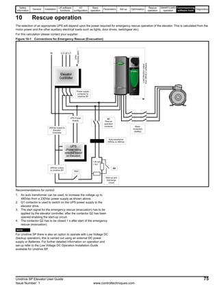
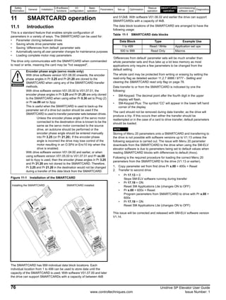
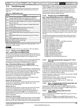
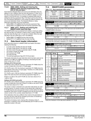
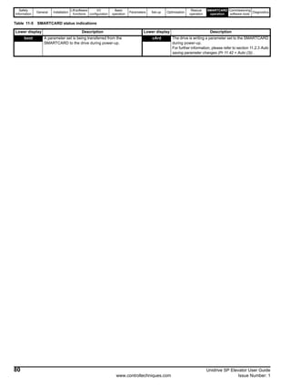
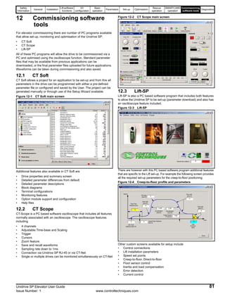
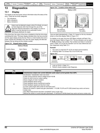
![Safety
Information
General Installation
Lift software
functions
I/O
configuration
Basic
operation
Parameters Set-up Optimisation
Rescue
operation
SMARTCARD
operation
Commissioning
software tools
Diagnostics
Unidrive SP Elevator User Guide 83
Issue Number: 1 www.controltechniques.com
13.2 Elevator specific diagnostics
This section covers specific diagnostics related to the SM-ELV (SM-
Applications, SM-Applications Lite) which is required for the Unidrive SP
Elevator solution.
13.2.1 Diagnostic parameters - Pr 0.12 = 4
N
If Pr 17.18 = 1 (SM-Applications, SM-Applications Lite watchdog enable)
an SLX.tO trip, (Solutions Module watchdog timeout) is displayed after
the elevator drive trips. This trip must be reset separately either via the
keypad reset button or by setting Pr xx.00 to 1070.
13.2.2 Error detection
The SM-ELV with the elevator software has both speed and distance
error detection, Trip 70 and Trip 71 detailed as follows. If either of these
trips occur refer to the following corrective actions.
Table 13-1 Error detection
In addition to the speed and distance error detection there are also
temperature and motor error detection features in the SM-ELV software
as detailed above.
Parameter Description Type Range Default Units Notes
0.13 [4] Zero speed threshold RW 250 5 rpm
0.14 [4] Not used
0.15 [4] Motor voltage RO 800 - V
0.16 [4] Maximum speed error RO 32000 - mm/s
0.17 [4] Maximum overload run RO 400.0 - %In
0.18 [4] Motor magnetised RO Bit 1 - - 1: Motor magnetised
0.19 [4] Brake output RO Bit 1 - - ON: Brake released / OFF: Brake applied
0.20 [4] Last trip RO - - -
0.21 [4] Previous trip RO - - -
0.22 [4] Speed controller output RO 400.0 - %In
0.23 [4] Terminal status RO 11111 - - T. 24/ 25/ 41/ 28/ 31 (see section 13.2.4)
0.24 [4] Terminal status RO 11111 - - T. 29/ 26/ 27/ 5/ 7 (see section 13.2.4)
0.25 [4] Speed error RO 10000 - mm/s
0.26 [4] Maximum speed error RW 10000 200 mm/s Setting = 10 x Pr 0.25[4] > 200
0.27 [4] Distance error RO 10000 - mm
0.28 [4] Maximum distance error RW 10000 200 mm Setting = 10 x Pr 0.27[4] > 200
0.29 [4] Speed error RO ± Pr 0.02 - rpm Drive encoder feedback control in open loop operation
0.30 [4] Speed feedback RO ± Pr 0.02 - rpm Drive encoder feedback control in open loop operation
NOTE
Trip
Code
Description Cause Corrective actions
Trip 70
Speed error
detection
Encoder feedback
Motor connections
Gain setting
Check motor and encoder connections
Check gain settings and phase angle.
Increase Threshold Pr 0.29 if necessary.
Disable following error detection by setting
Pr 0.29 = 0.
Trip 71
Distance error
detection
Encoder feedback
Motor connections
Gain setting
Check motor and encoder connections
Check gain setting and phase angle.
Increase Threshold Pr 19.18 if necessary.
Disable following error detection by setting
Pr 19.18 = 0.
Trip 73
Temperature
monitoring
Drive temperature is below 0°C
(default Pr 70.81)
If drive temperature is below 0°C a pre
heater is required to ensure the minimum
temperature is above 0°C
Trip 76
Motor fluxed
detection
Motor contactor not closed
Incorrect motor map settings
Check timing of any output contactors
Ensure motor map is set up correctly
Trip 77 Motor phase loss
Motor phase loss due to
intermittent / broken connection
Check all motor connections are secure](https://image.slidesharecdn.com/unispelevator-140613204659-phpapp02/85/Uni-sp-elevator-83-320.jpg)
![Safety
Information
General Installation
Lift software
functions
I/O
configuration
Basic
operation
Parameters Set-up Optimisation
Rescue
operation
SMARTCARD
operation
Commissioning
software tools
Diagnostics
84 Unidrive SP Elevator User Guide
www.controltechniques.com Issue Number: 1
13.2.3 Control diagnostics
If the normal run command is applied and the Unidrive SP elevator
solution does not start or a trip is generated at this stage, then proceed
as follows:
Figure 13-4 Diagnostic control interface
13.2.4 Control terminal status
For analysing the status of the control terminals these are arranged in
groups and displayed as follows in Pr 0.23[4] and Pr 0.24[4].
Figure 13-5 Control terminal status
13.3 Unidrive SP trip codes
State
Dispay
state
Terminal 30
Pr 8.07
"inh" (disabled)
Speed
selected ?
Pr 18.10
"run"
(enabled)
Pr OR8.03
Pr OR8.04
Pr 8.06
Selected
speed
Pr 18.1x
= 1810
(no speed selected)
= 1
(active)
Check Logic
Polarity
Pr and8.27
Signal at
Terminal 30
= 0 (not active)
Check UD70
present and
program
running.
(Pr )18.01
> 1810
(Speed selected)
= 0
Check
external brake
control circuit
Adjust the
speed
selected
Brake
output
Pr 8.02
> 0
= 0
(active)
Motor
magnetised
Pr 18.43
= 1
Check state of
the motor
conductor
= 0
(not active)
Check Control
Signals at the
Terminals
= 0 (not active)
Ckeck
Terminal
function
programming
= 1
(active)
T. 29: Bit 0
T. 26: Bit 1
T. 27: Bit 2
Pr [4]0.23
T. 7: Bit 4
T. 5: Bit 3
T. 24: V > 0,3m/s
T. 25: Not Brake
T. 41/42: Drive Healthy
Pr [4]0.24
T. 31: Enable
T. 28: Up / Down
X0
X1
X2
X3
X4
X1
X3
X2
X4
X0
Trip Diagnosis
C.Acc SMARTCARD trip: SMARTCARD Read / Write fail
185
Check SMARTCARD is fitted / located correctly
Replace SMARTCARD
C.bUSY SMARTCARD trip: SMARTCARD can not perform the required function as it is being accessed by a Solutions Module
178 Wait for the Solutions Module to finish accessing the SMARTCARD and then re-attempt the required function
C.Chg SMARTCARD trip: Data location already contains data
179
Erase data in data location
Write data to an alternative data location
C.cPr SMARTCARD trip: The values stored in the drive and the values in the data block on the SMARTCARD are different
188 Press the red reset button
C.dAt SMARTCARD trip: Data location specified does not contain any data
183 Ensure data block number is correct](https://image.slidesharecdn.com/unispelevator-140613204659-phpapp02/85/Uni-sp-elevator-84-320.jpg)
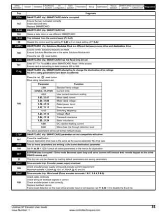
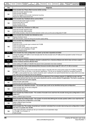
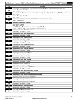
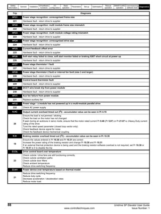
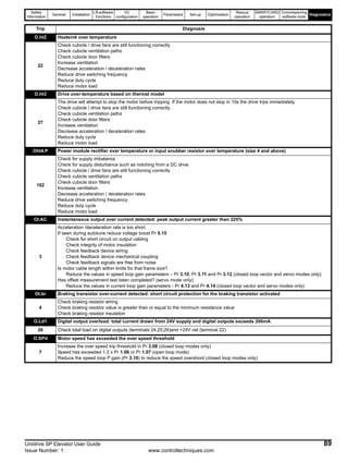
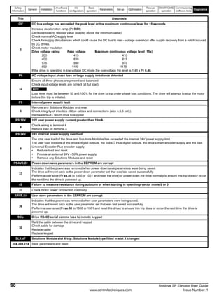
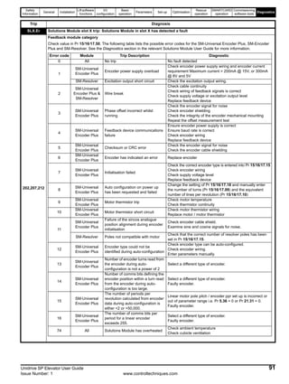
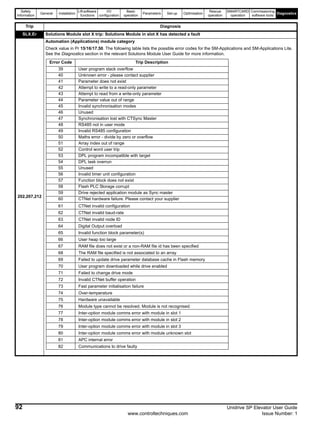
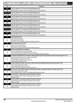
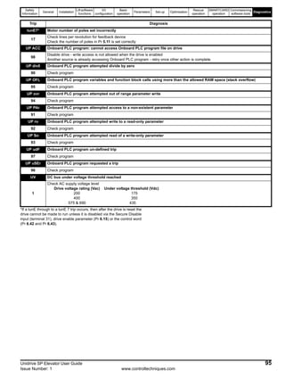
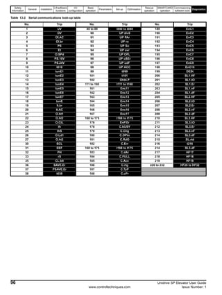
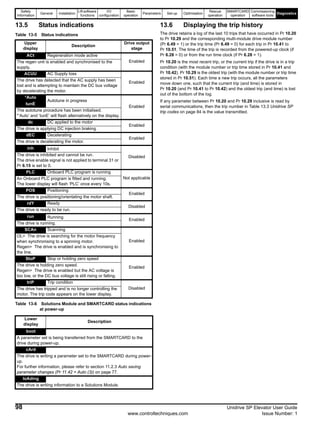


This document provides instructions for installing and operating a universal variable speed AC drive for elevator systems. It contains safety warnings and describes how to connect the drive to motors, encoders, and other system components. The document also summarizes the lift software functions such as creep-to-floor positioning and direct-to-floor positioning. Installation, I/O configuration, basic operation, and optimizing parameters are covered to help commission the elevator solution.


![Ct2000 pro plus_manual_english[1]](https://cdn.slidesharecdn.com/ss_thumbnails/ct2000proplusmanualenglish1-140613213527-phpapp02-thumbnail.jpg?width=640&height=640&fit=bounds)


![Ct2000 es manual_english_version_1[1].0](https://cdn.slidesharecdn.com/ss_thumbnails/ct2000esmanualenglishversion11-140613213448-phpapp01-thumbnail.jpg?width=640&height=640&fit=bounds)


