Downloaded 369 times
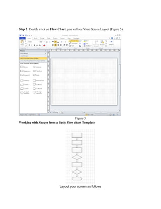
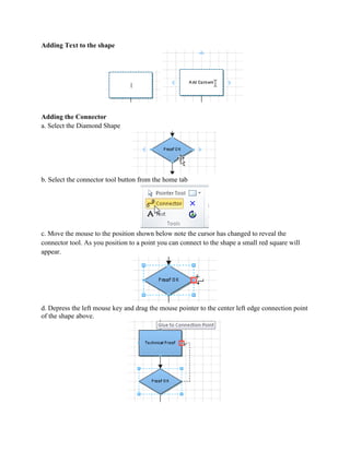
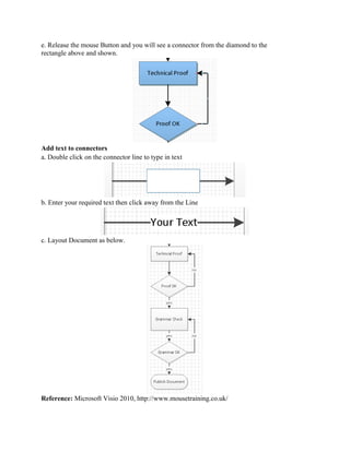

This document provides a tutorial for creating logical diagrams and flowcharts in Microsoft Visio 2010. It first introduces Visio and the objectives of the tutorial, which are to create a logical diagram, add text to diagrams, and create a flowchart. The tutorial then provides step-by-step instructions on how to start Visio, create a new drawing, add shapes and stencils, draw a logic diagram for an SN74LS00 chip including gates, pins and wires. It also demonstrates how to add text, flip-flops, I/O ports and create a basic flowchart with shapes, connectors and text. The tutorial includes 18 figures to illustrate the steps.


![Getting Started with Apache Spark: Big Data Made Simple [Free Meetup]](https://cdn.slidesharecdn.com/ss_thumbnails/apachesparkgettingstarted-260203175547-8361bcc3-thumbnail.jpg?width=640&height=640&fit=bounds)


