Downloaded 110 times
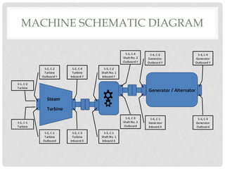
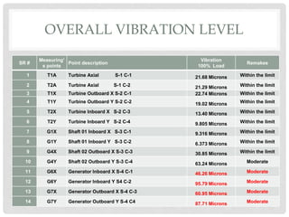
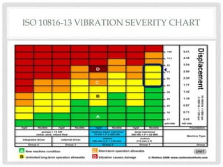
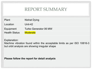
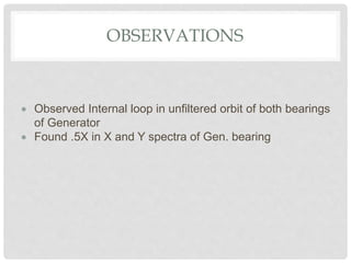
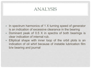
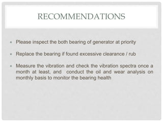
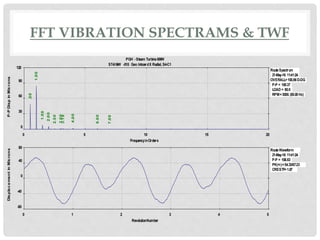
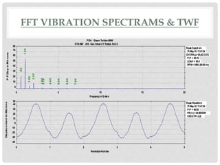
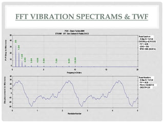
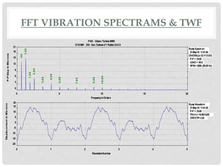
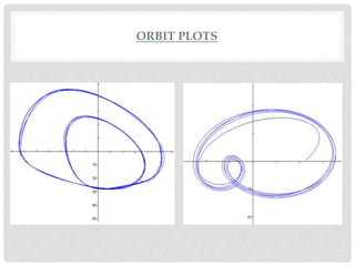
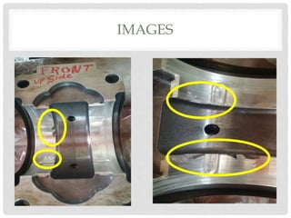
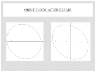

The document is a vibration analysis report for a turbo generator at Nishat Dying Mills powerhouse. It analyzes vibration measurements taken at 14 points on the turbine and generator components at 100% load. Some measurements showed moderate vibration levels. Analysis of the generator bearing spectra and orbit plots indicated issues like excessive clearance, internal rubbing, and unstable lubrication film between the bearing and journal. Recommendations included inspecting and possibly replacing the generator bearings, and ongoing monthly monitoring and analysis to track bearing health.


