Downloaded 143 times


![180
199200
1582
19520419520419590.8
121.62121.62121.62121.62121.62121.62121.62121.62
1596
15001500
1500
E97 Ventilated Facade Systems
technical catalogue 2014
Building Physics E97
DIMENSIONING OF MAIN SUPPORTING PROFILE
Simply supproted beam with one fixed and one movable supports – area A
Application point of the force F from the wind load on the profile is physically the hanger.
All static calculations must be verified by a responsible structural/façade engineer on site.
Dimensioning of profile E97101
Initial data:
H = 0-15 m (middle zone)
g = 0.065 kN/m2
f1 = 1,25
q = 0,41 kN/m2
cp = 0,8 (wind pressure)
cp = - 0,6 (wind suction)
h = 1.828 m
b = 1,5 m
s = 1.828 m
Defining the loads:
Self weight - dead load
V = g.3h.b = 0,066. 1.828 . 1,5 = 0.180 kN
Wind load of the profile area
Wp = f1 . q . cp . h . b =
= 1,25 . 0,41 . 0,8 . 1,582 . 1,5 = 0,973 kN
Ws = q . cp . h . b =
= 0,41 . (-0,6) . 1,582 . 1,5 = (-0,584) = 0,584 kN
F = Wp/quantity of the hangers
F= 0,973/8 = 0,122 kN = 121,6 N
Permissible deflection:
[f] = s/200
[f]= 1582/200 = [7,91 mm]
Self weight - dead load
V=g.3h.b
Wind load-presure
For determining the maximum permissible wind load the
following formulae apply:
Wp = f1 . q . cp . h/2 . b
Wind load-suction
Ws = q . cp . h/2 .b
where:
V - load, kN
g - weight of main vertical profiles and façade
material, kN/m2
Wp - wind pressure, kN
Ws - wind suction, kN
f1 - correction factor
q - dynamic load, kN/m2
cp - correction factor (wind pressure)
h - distance between fixing brackets, m
b - distance between main vertical profiles, m
H - building height, m
s - distance between fixing brackets
Results of the calculation
Max deflection = 5,41 mm [7,91 mm]
Max Stress = 62,949N/mm2
[160N/mm2
]
Max bending momnet = 191,29 Nm
Safety Factor = 2,5417 [2]
Conclusion:
Based on the conditions above, profile E97101 provides
the necessary bearing capacity.
The calculation was made using Autocad Mechanical
static module.
33](https://image.slidesharecdn.com/technicalvfscatalogue-170124120630/85/Ventilated-Facade-Systems-33-320.jpg)
![4850
100250200250200250200300200300200300200300200300200300200300
1616.71616.71616.7
471.5
149.15149.15149.15149.15149.15149.15149.15149.15149.15149.15149.15149.15149.15149.15149.15149.15149.15149.15149.15149.15
1500 1500
4850
1500
E97 Ventilated Facade Systems
technical catalogue 2014
Building Physics E97
DIMENSIONING OF MAIN SUPPORTING PROFILE
Continuous beam with one fixed and three movable supports – area B
Application point of the force F from the wind load on the profile is physically the hanger.
All static calculations must be verified by a responsible structural/façade engineer on site.
Dimensioning of profile E97101
Initial data:
H = 0-15 m (middle zone)
g = 0.065 kN/m2
f1 = 1,25
q = 0,41 kN/m2
cp = 0,8 (wind pressure)
cp= - 0,6 (wind suction)
h = 4.85 m
b = 1,5 m
s = 1.616 m
Defining the loads:
Own weight - dead load
V = g.3h.b = 0,065. 4,85 . 1,5 = 0.472 kN
Wind load of the profile area
Wp = f1 . q . cp . h . b =
= 1,25 . 0,41 . 0,8 . 4.85 . 1.5 = 2,983 kN
Ws = κz . q . cp . h . b =
= 0,41 . (-0,6) . 4.85 . 1.5 = (-1,342) =
1,789 kN
F = Wp/quantity of the hangers
F= 2,983/20 = 0,149 kN = 149,1 N
Permissible deflection:
[f] = s/200
[f]= 1616/200 = [8.08mm]
Own weight - dead load
V = g.3h.b
Wind load-presure
For determining the maximum permissible wind
load the following formulae apply:
Wp = f1 . q . cp . h/2 . b
Wind load-suction
Ws = q . cp . h/2 .b
where:
V - load, kN
g - weight main vertical profiles and façade
material, kN/m2
Wp - wind pressure, kN
Ws - wind suction, kN
f1 - correction factor
q - dynamic load, kN/m2
cp - correction factor (wind pressure)
h - distance between fixing brackets, m
b - distance between main vertical profiles, m
H - building height, m
s - distance between fixing brackets
Results of the calculation
Max deflection = 3,45 mm [8.08 mm]
Max Stress = 55,924N/mm2
[160N/mm2
]
Max bending moment = 169,94 Nm
Safety Factor = 2,8610 [2]
Conclusion:
Based on the conditions above, profile E97101
provides the necessary bearing capacity.
The calculation was made using AutoCad
Mechanical deflection line module.
34](https://image.slidesharecdn.com/technicalvfscatalogue-170124120630/85/Ventilated-Facade-Systems-34-320.jpg)


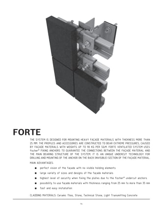


The document provides a comprehensive overview of ventilated façade systems (VFS) designed by etem, highlighting their architectural solutions and sustainability aspects. Key features include energy efficiency, fire resistance, sound insulation, and ease of maintenance, alongside technical specifications and material certifications. etem's focus on customer-oriented design and environmentally sustainable practices is emphasized throughout the document.