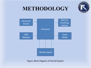
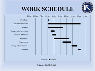
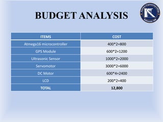
KANTIPUR ENGINEERING
COLLEGE
A MINOR PROJECT PORPOSAL ON
“VECHICLE COLLISION PREVENTION”
BY:
-Binaya Koirala (13/BEX/2071)
-Bishal Trital (14/BEX/2071)
-Gagan Bdr. Pradhan (16/BEX/2071)
-Milan Raj Thapa (29/BEX/2071)
CONTENTS
 Introduction
 Objectives
 Features
 System Requirement
 Methodology
 Application
 Expected Output
 Work Schedule
 Budget analysis
 References
INTRODUCTION
First demonstrated at Hughes Research Lab.
GPS module and Ultrasonic Sensor based
system.
Vehicle and obstacle detection.
Automatically stops the vehicle, if any danger
occurs.
OBJECTIVES
To reduce accidents and ensure the safety.
To provide information about current position.
To notify driver about nearest approaching
vehicle.
FEATURES
Driver and passenger safety.
Can be re-modeled for more distance
coverage.
Can alert riders about an approaching vehicle.
Automated after embedded in the vehicle.
SYSTEM REQUIREMENT
1.Software requirement
1.1 Atmel Studio
 Integrated development platform for
developing AVR microcontroller.
1.2 Proteus
Software developed to design, test and
simulate the work.
2.Hardware Requirement
2.1 Atmega16 Microcontroller
 Low power consumption device with 131
powerful instruction.
2.2 Servomotor
 Consist of a suitable motor coupled to a
sensor for position feedback.
2.Hardware requirement(contd…)
2.3 Ultrasonic Sensor;
 Device used for obstacle detection.
2.4 GPS Module;
 Device capable of receiving information from
GPS satellites.
METHODOLOGY
Figure. Block Diagram of Overall System
Processor
Ultrasonic
Sensor
Alert on
incoming
Vehicle
GPS
Module
Auto
Brake
Vehicle speed
APPLICATION
 Applicable on any road network.
 Manage traffic.
 Night travels can be safer.
 Current position notification.
EXPECTED OUTPUT
Automated action stops the vehicle.
Ultrasonic sensor would help to avoid close
collisions.
 Display current location.
WORK SCHEDULE
29-Jun 18-Aug 7-Oct 26-Nov 15-Jan 6-Mar 25-Apr 14-Jun 3-Aug 22-Sep
Work Begin
Documentation Starts
Research
Designing the Schematics
Collection of Material
Assembling
Programming
Testing and modification
Debugging
Start Date Duration
Figure. Gantt Chart
BUDGET ANALYSIS
ITEMS COST
Atmega16 microcontroller 400*2=800
GPS Module 600*2=1200
Ultrasonic Sensor 1000*2=2000
Servomotor 3000*2=6000
DC Motor 600*4=2400
LCD 200*2=400
TOTAL 12,800
REFERENCES
Navistar GPS space segment/Navigation user
interfaces.
“Ultrasonic testing”.testexndt.co.uk.2016-08-
04.
“Forward Collision Warning Requirement
project final report-task 1”.National Highway
Safety Administration.
“THANK YOU”

Vehicle collision prevention project

  • 1.
    KANTIPUR ENGINEERING COLLEGE A MINORPROJECT PORPOSAL ON “VECHICLE COLLISION PREVENTION” BY: -Binaya Koirala (13/BEX/2071) -Bishal Trital (14/BEX/2071) -Gagan Bdr. Pradhan (16/BEX/2071) -Milan Raj Thapa (29/BEX/2071)
  • 2.
    CONTENTS  Introduction  Objectives Features  System Requirement  Methodology  Application  Expected Output  Work Schedule  Budget analysis  References
  • 3.
    INTRODUCTION First demonstrated atHughes Research Lab. GPS module and Ultrasonic Sensor based system. Vehicle and obstacle detection. Automatically stops the vehicle, if any danger occurs.
  • 4.
    OBJECTIVES To reduce accidentsand ensure the safety. To provide information about current position. To notify driver about nearest approaching vehicle.
  • 5.
    FEATURES Driver and passengersafety. Can be re-modeled for more distance coverage. Can alert riders about an approaching vehicle. Automated after embedded in the vehicle.
  • 6.
    SYSTEM REQUIREMENT 1.Software requirement 1.1Atmel Studio  Integrated development platform for developing AVR microcontroller. 1.2 Proteus Software developed to design, test and simulate the work.
  • 7.
    2.Hardware Requirement 2.1 Atmega16Microcontroller  Low power consumption device with 131 powerful instruction. 2.2 Servomotor  Consist of a suitable motor coupled to a sensor for position feedback.
  • 8.
    2.Hardware requirement(contd…) 2.3 UltrasonicSensor;  Device used for obstacle detection. 2.4 GPS Module;  Device capable of receiving information from GPS satellites.
  • 9.
    METHODOLOGY Figure. Block Diagramof Overall System Processor Ultrasonic Sensor Alert on incoming Vehicle GPS Module Auto Brake Vehicle speed
  • 10.
    APPLICATION  Applicable onany road network.  Manage traffic.  Night travels can be safer.  Current position notification.
  • 11.
    EXPECTED OUTPUT Automated actionstops the vehicle. Ultrasonic sensor would help to avoid close collisions.  Display current location.
  • 12.
    WORK SCHEDULE 29-Jun 18-Aug7-Oct 26-Nov 15-Jan 6-Mar 25-Apr 14-Jun 3-Aug 22-Sep Work Begin Documentation Starts Research Designing the Schematics Collection of Material Assembling Programming Testing and modification Debugging Start Date Duration Figure. Gantt Chart
  • 13.
    BUDGET ANALYSIS ITEMS COST Atmega16microcontroller 400*2=800 GPS Module 600*2=1200 Ultrasonic Sensor 1000*2=2000 Servomotor 3000*2=6000 DC Motor 600*4=2400 LCD 200*2=400 TOTAL 12,800
  • 14.
    REFERENCES Navistar GPS spacesegment/Navigation user interfaces. “Ultrasonic testing”.testexndt.co.uk.2016-08- 04. “Forward Collision Warning Requirement project final report-task 1”.National Highway Safety Administration.
  • 15.