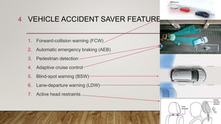
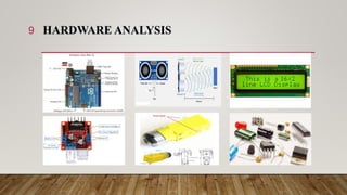
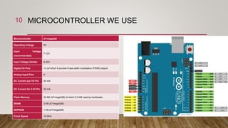
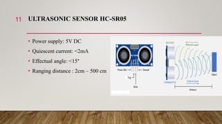
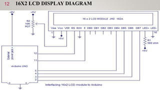
DESIGN AND IMPLEMENTATION
OF
VEHICLE ACCIDENT SAVER
SONARGAON UNIVERSITY (SU)
1
Supervised By
Jannatul Nazrana
Lecturer
Department of EEE
Name ID
Md. Khadimul
Islam
EEE160300918
5
Md. Kamrul Islam
Galib
EEE160300910
6
Md. Romjan Ali
EEE160300908
9
Md. Masum
Billah
EEE160300911
7
Md. Ariful lslam
EEE1602008245
PresentedBy
2
OUTLINE
Vehicle accident saver features…..4
Block Diagram……………………5
Flowchart………………..……….6
Circuit Diagram …………………7
Components used in our project...8
Hardware Analysis………………...9
Microcontroller We use …….……10
Ultrasonic Sensor HC-05
………………..11
16x2 LCD Display Diagram …………….12
L293D H-Bridge Dual Motor Driver
…….13
Gear Motor ……………………………….14
Software Arduino IDE ……………………
15
Real Project Photo
………………………..16
Project
3
VEHICLE ACCIDENT SAVER FEATURES
1. Forward-collision warning (FCW)
2. Automatic emergency braking (AEB)
3. Pedestrian detection
4. Adaptive cruise control
5. Blind-spot warning (BSW)
6. Lane-departure warning (LDW)
7. Active head restraints
4
BLOCK DIAGRAM5
FLOWCHART6
CIRCUIT DIAGRAM7
COMPONENTS USED IN OUR PROJECT8
HARDWARE ANALYSIS9
MICROCONTROLLER WE USE
Arduino Uno R3
Microcontroller ATmega328
Operating Voltage 5V
Input Voltage
(recommended)
7-12V
Input Voltage (limits) 6-20V
Digital I/O Pins 14 (of which 6 provide Pulse-width modulation (PWM) output)
Analog Input Pins 6
DC Current per I/O Pin 40 mA
DC Current for 3.3V Pin 50 mA
Flash Memory 32 KB (ATmega328) of which 0.5 KB used by bootloader
SRAM 2 KB (ATmega328)
EEPROM 1 KB (ATmega328)
Clock Speed 16 MHz
10
ULTRASONIC SENSOR HC-SR05
• Power supply: 5V DC
• Quiescent current: <2mA
• Effectual angle: <15°
• Ranging distance : 2cm – 500 cm
11
16X2 LCD DISPLAY DIAGRAM12
L293D H-BRIDGE DUAL MOTOR DRIVER13
GEAR MOTOR
Features
Rated Voltage: 5.0V DC
Working Voltage: 3.0V - 6.0V
DC Current: (Low load) 3V-150mA , 6V-200mA
Speed: (Low load) 3V-90rpm±10% , 6V-200rpm±10%
Torque: max. 0.8kg/cm
Reduction ratios: 1:48
Brush-type: Brush
Body Size: 70mm x 37mm x 23mm
Shaft Size: 8mm x 2mm diameter Weight: 17.5 gm
14
SOFTWARE
ARDUINO IDE
The Arduino Integrated
Development Environment (IDE)
is a cross-platform application
(for Windows, macOS, Linux)
that is written in functions from
C and C++. It is used to write
and upload programs to Arduino
compatible boards, but also, with
the help of 3rd party cores, other
vendor development boards.
15
PROJECT OUTCOME
• Save car from damage
• Make an Idea to save people life
• Make an Idea to road safety
• Controlling road rule
• Avoid unexpected accident
17
FUTURE WORKS
• This device will connect as Internet of things - IOT (5G)
• This Device can communicate with nearest hospital, fire service and police
station.
• Our device can use in any vehicle to protect the vehicle and human life.
• Our device will be portable.
• Our device can work with Smart mobile and web application.
• All data of vehicle can be store as Black Box for future development.
18
REFERENCES
1. Shanjedul Hassan “https://www.academia.edu/26908561/Distance_Measurement_for_car_Accident”
2. Maniruzzaman, K.M. and Mirta Raktim,(2005).Road Accidents in Bangladesh. IATSS Research,
Vol.29,No.2,
3. Mannan, M.S. and Karim, M. (1999). Road accidents in metropolitan Dhaka, Bangladesh. IATSS
4. Ministry of Communications, 1994. Rehabilitation of Works between Savar to Aricha Segment of
N5 Highway, Tender Document, Bangladesh
5. Roads and Highways Department, 1995. Development of Geometric Design Standards, Final
Report, volume VIIB, Road Materials and Standards Study Bangladesh, Ministry of Communications,
Dhaka
6. Hybrid Artificial Intelligent Systems: 12th International Conference,
19
Car Accident Saver

Car Accident Saver

  • 1.
    DESIGN AND IMPLEMENTATION OF VEHICLEACCIDENT SAVER SONARGAON UNIVERSITY (SU) 1
  • 2.
    Supervised By Jannatul Nazrana Lecturer Departmentof EEE Name ID Md. Khadimul Islam EEE160300918 5 Md. Kamrul Islam Galib EEE160300910 6 Md. Romjan Ali EEE160300908 9 Md. Masum Billah EEE160300911 7 Md. Ariful lslam EEE1602008245 PresentedBy 2
  • 3.
    OUTLINE Vehicle accident saverfeatures…..4 Block Diagram……………………5 Flowchart………………..……….6 Circuit Diagram …………………7 Components used in our project...8 Hardware Analysis………………...9 Microcontroller We use …….……10 Ultrasonic Sensor HC-05 ………………..11 16x2 LCD Display Diagram …………….12 L293D H-Bridge Dual Motor Driver …….13 Gear Motor ……………………………….14 Software Arduino IDE …………………… 15 Real Project Photo ………………………..16 Project 3
  • 4.
    VEHICLE ACCIDENT SAVERFEATURES 1. Forward-collision warning (FCW) 2. Automatic emergency braking (AEB) 3. Pedestrian detection 4. Adaptive cruise control 5. Blind-spot warning (BSW) 6. Lane-departure warning (LDW) 7. Active head restraints 4
  • 5.
  • 6.
  • 7.
  • 8.
    COMPONENTS USED INOUR PROJECT8
  • 9.
  • 10.
    MICROCONTROLLER WE USE ArduinoUno R3 Microcontroller ATmega328 Operating Voltage 5V Input Voltage (recommended) 7-12V Input Voltage (limits) 6-20V Digital I/O Pins 14 (of which 6 provide Pulse-width modulation (PWM) output) Analog Input Pins 6 DC Current per I/O Pin 40 mA DC Current for 3.3V Pin 50 mA Flash Memory 32 KB (ATmega328) of which 0.5 KB used by bootloader SRAM 2 KB (ATmega328) EEPROM 1 KB (ATmega328) Clock Speed 16 MHz 10
  • 11.
    ULTRASONIC SENSOR HC-SR05 •Power supply: 5V DC • Quiescent current: <2mA • Effectual angle: <15° • Ranging distance : 2cm – 500 cm 11
  • 12.
  • 13.
    L293D H-BRIDGE DUALMOTOR DRIVER13
  • 14.
    GEAR MOTOR Features Rated Voltage:5.0V DC Working Voltage: 3.0V - 6.0V DC Current: (Low load) 3V-150mA , 6V-200mA Speed: (Low load) 3V-90rpm±10% , 6V-200rpm±10% Torque: max. 0.8kg/cm Reduction ratios: 1:48 Brush-type: Brush Body Size: 70mm x 37mm x 23mm Shaft Size: 8mm x 2mm diameter Weight: 17.5 gm 14
  • 15.
    SOFTWARE ARDUINO IDE The ArduinoIntegrated Development Environment (IDE) is a cross-platform application (for Windows, macOS, Linux) that is written in functions from C and C++. It is used to write and upload programs to Arduino compatible boards, but also, with the help of 3rd party cores, other vendor development boards. 15
  • 17.
    PROJECT OUTCOME • Savecar from damage • Make an Idea to save people life • Make an Idea to road safety • Controlling road rule • Avoid unexpected accident 17
  • 18.
    FUTURE WORKS • Thisdevice will connect as Internet of things - IOT (5G) • This Device can communicate with nearest hospital, fire service and police station. • Our device can use in any vehicle to protect the vehicle and human life. • Our device will be portable. • Our device can work with Smart mobile and web application. • All data of vehicle can be store as Black Box for future development. 18
  • 19.
    REFERENCES 1. Shanjedul Hassan“https://www.academia.edu/26908561/Distance_Measurement_for_car_Accident” 2. Maniruzzaman, K.M. and Mirta Raktim,(2005).Road Accidents in Bangladesh. IATSS Research, Vol.29,No.2, 3. Mannan, M.S. and Karim, M. (1999). Road accidents in metropolitan Dhaka, Bangladesh. IATSS 4. Ministry of Communications, 1994. Rehabilitation of Works between Savar to Aricha Segment of N5 Highway, Tender Document, Bangladesh 5. Roads and Highways Department, 1995. Development of Geometric Design Standards, Final Report, volume VIIB, Road Materials and Standards Study Bangladesh, Ministry of Communications, Dhaka 6. Hybrid Artificial Intelligent Systems: 12th International Conference, 19