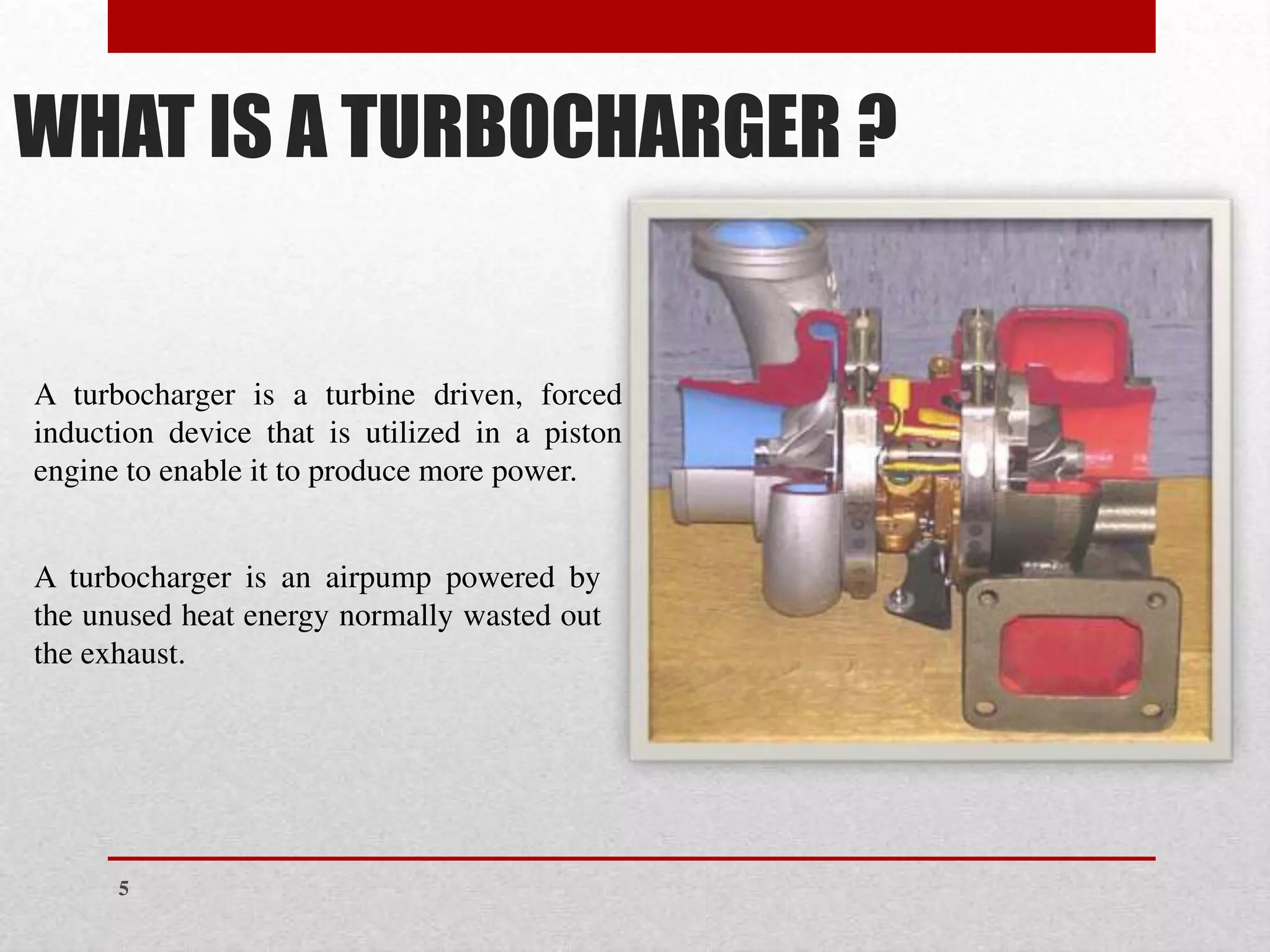
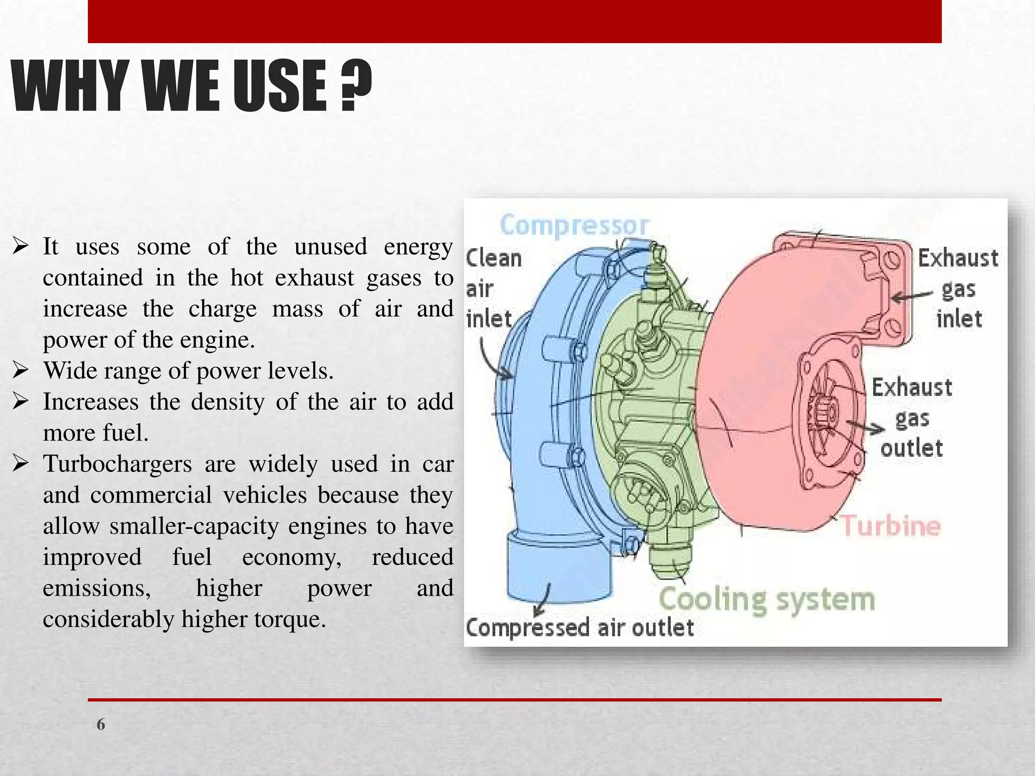
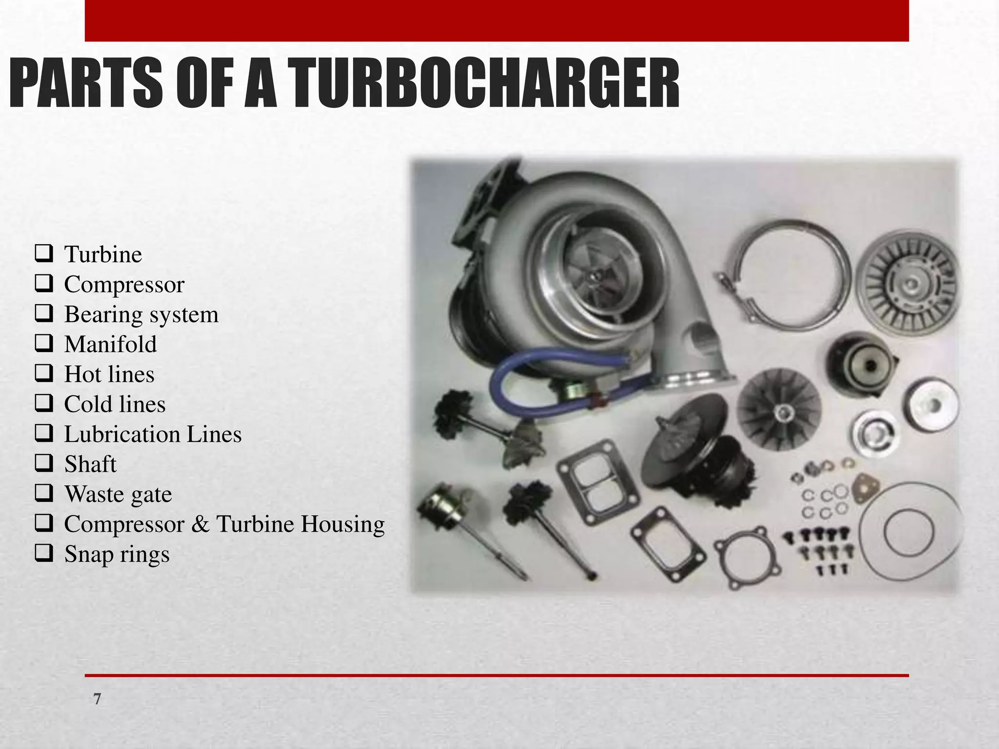
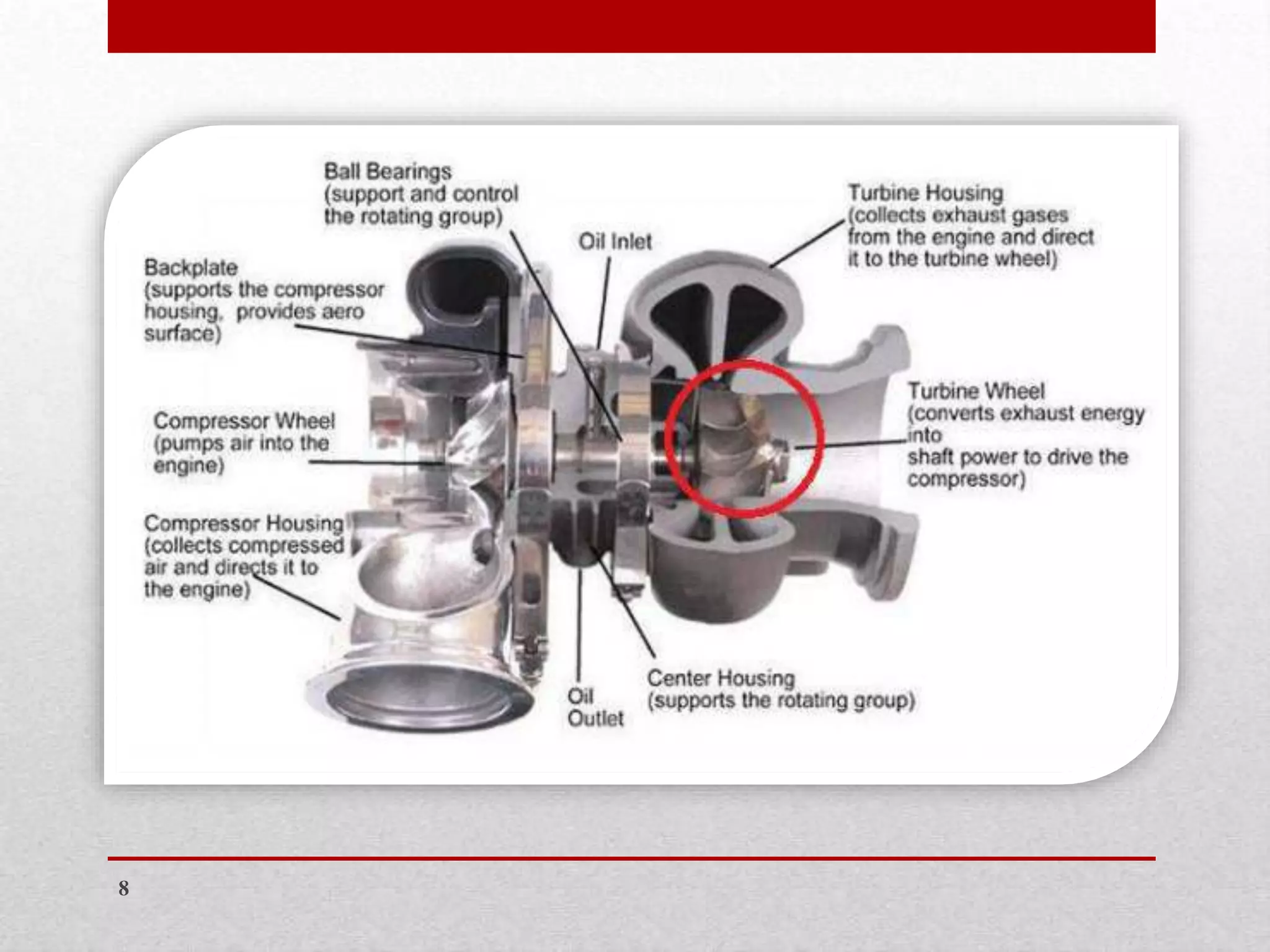
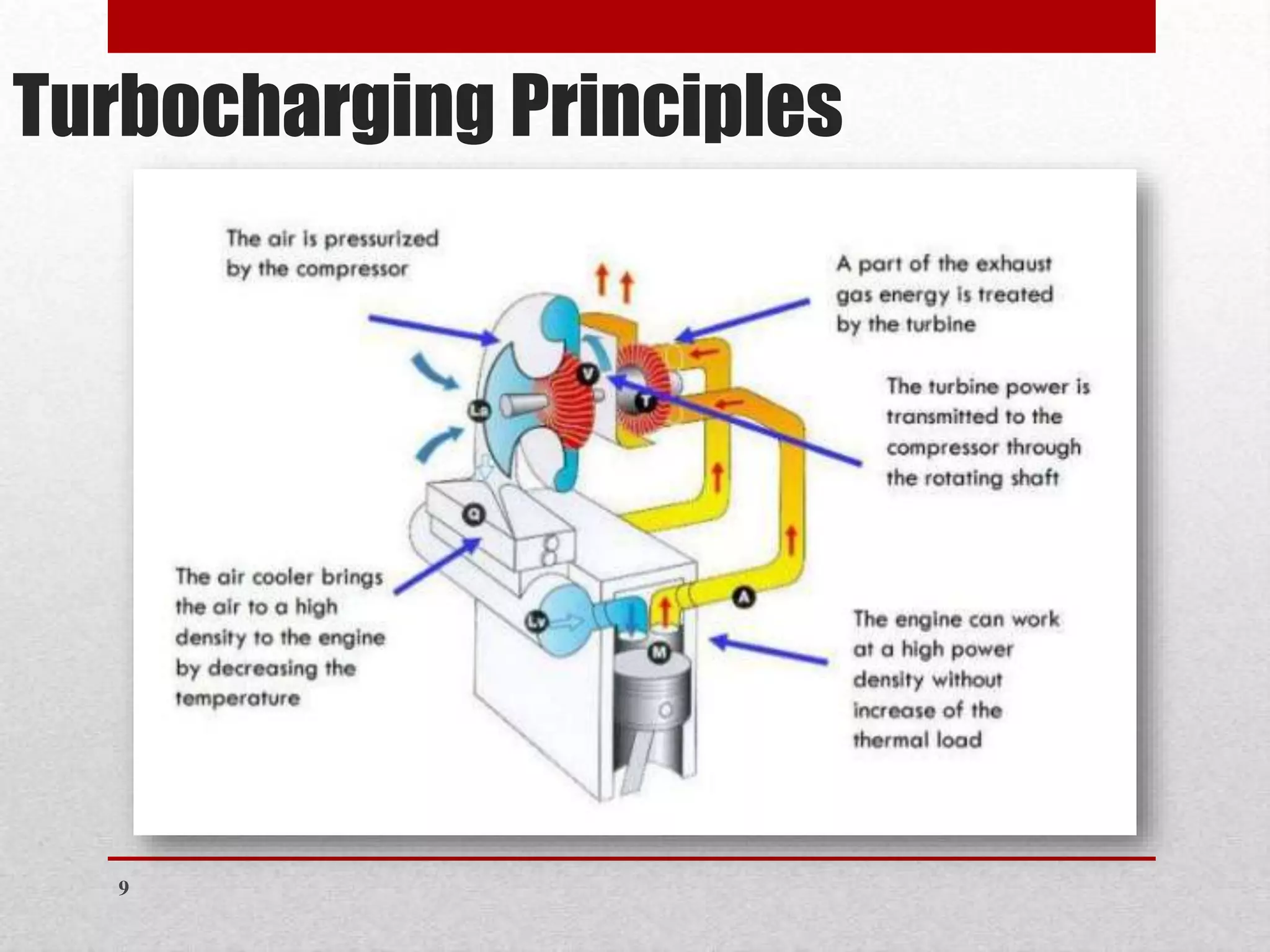
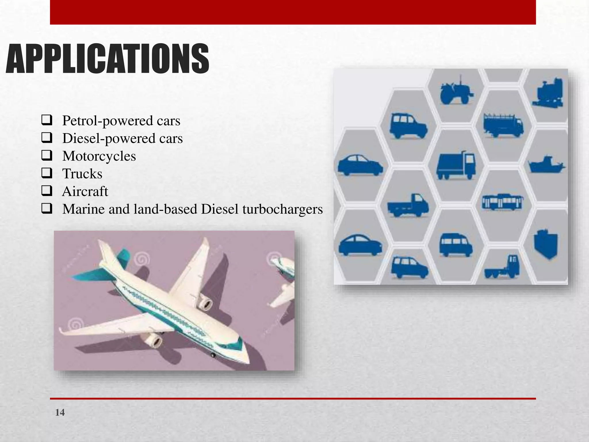
1
Turbocharging of
the Piston Engine
Program: BSAMT Semester: 3
Course: Aircraft Engines Reg. No: 70074041
Presented To: Sir M. Dawood Bukhari
Presented By: OMER ISHFAQ
2
CONTENTS
❖ History
❖ What is a Turbocharger
❖ Why We Use
❖ Parts of a Turbocharger
❖ Turbocharging Principles
❖ Turbocharger Design and Operation
❖ Turbocharger Vs. Supercharger
❖ Boost Control
❖ Turbocharger Failures
❖ Applications
❖ Advantages and Disadvantages of Turbocharger
❖ Conclusion
3
4
The turbocharger was invented by Swiss engineer Alfred Büchi (1879-1959), the head of
Diesel engine research at Gebrüder Sulzer engine manufacturing company in Winterthur,
who received a patent in 1905 for using a compressor driven by exhaust gases to force air
into an internal combustion engine to increase power output, but it took another 20 years
for the idea to come to fruition.
History
WHAT IS A TURBOCHARGER ?
A turbocharger is a turbine driven, forced
induction device that is utilized in a piston
engine to enable it to produce more power.
A turbocharger is an airpump powered by
the unused heat energy normally wasted out
the exhaust.
5
WHY WE USE ?
➢ It uses some of the unused energy
contained in the hot exhaust gases to
increase the charge mass of air and
power of the engine.
➢ Wide range of power levels.
➢ Increases the density of the air to add
more fuel.
➢ Turbochargers are widely used in car
and commercial vehicles because they
allow smaller-capacity engines to have
improved fuel economy, reduced
emissions, higher power and
considerably higher torque.
6
PARTS OF A TURBOCHARGER
❑ Turbine
❑ Compressor
❑ Bearing system
❑ Manifold
❑ Hot lines
❑ Cold lines
❑ Lubrication Lines
❑ Shaft
❑ Waste gate
❑ Compressor & Turbine Housing
❑ Snap rings
7
8
Turbocharging Principles
9
❑ A turbocharger consists of two chambers connected by a center housing.
❑ The two chambers contain a turbine wheel and a compressor wheel connected by a shaft
which passes through the center housing.
❑ The exhaust drives the turbine wheel on the left, which is connected to the impeller wheel on
the right through a shaft. The bushings that support the shaft are lubricated with engine oil
under pressure.
❑ Turbocharger response time is directly related to the size of the turbine and compressor
wheels.
❑ Small wheels accelerate rapidly; large wheels accelerate slowly.
❑ While small wheels would seem to have an advantage over larger ones, they may not have
enough airflow capacity for an engine.
❑ To minimize turbo lag, the intake and exhaust breathing capacities of an engine must be
matched to the exhaust and intake airflow capabilities of the turbocharger.
TURBOCHARGER DESIGN AND
OPERATION
10
11
BOOST CONTROL
❑ Both supercharged and turbocharged systems are designed to provide a
pressure greater than atmospheric pressure in the intake manifold.
❑ This increased pressure forces additional amounts of air into the combustion
chamber over what would normally be forced in by atmospheric pressure.
❑ This increased charge increases engine power.
Relief Valves
A relief valve vents pressurized air from the connecting pipe between the outlet of the
turbocharger and the throttle whenever the throttle is closed during boost, such as during shifts.
A blow-off valve is used in some turbocharged systems to relieve boost pressure during
deceleration.
Wastegate
A turbocharger uses exhaust gases to increase boost, which causes the engine to make more
exhaust gases, which in turn increases the boost from the turbocharger. To prevent overboost and
severe engine damage, most turbocharger systems use a wastegate. A wastegate is a valve similar
to a door that can open and close. The wastegate is a bypass valve at the exhaust inlet to the
turbine. It allows all of the exhaust into the turbine, or it can route part of the exhaust past the
turbine to the exhaust system.
12
TURBOCHARGER FAILURES
▪ When turbochargers fail to function correctly, a drop in power is noticed.
▪ To restore proper operation, the turbocharger must be rebuilt, repaired, or replaced.
▪ It is not possible to simply remove the turbocharger, seal any openings, and still maintain
decent drivability.
13
APPLICATIONS
❑ Petrol-powered cars
❑ Diesel-powered cars
❑ Motorcycles
❑ Trucks
❑ Aircraft
❑ Marine and land-based Diesel turbochargers
14
ADVANTAGES and DISADVANTAGES
❑ Petrol Consumption
❑ Safety
❑ Eco-friendly
❑ Noise Pollution
❑ Driving Pleasure
❑ Installation
❑ System
❑ Cost
❑ Driving
15
CONCLUSION
❑ It’s a forced induction device
❑ Increasing the efficiency of an engine
❑ Too much boost can result into preignition
and knocking
❑ Half's the fuel consumption in an engine
16
17

Turbocharging of the Piston Engine.pdf

  • 1.
  • 2.
    Turbocharging of the PistonEngine Program: BSAMT Semester: 3 Course: Aircraft Engines Reg. No: 70074041 Presented To: Sir M. Dawood Bukhari Presented By: OMER ISHFAQ 2
  • 3.
    CONTENTS ❖ History ❖ Whatis a Turbocharger ❖ Why We Use ❖ Parts of a Turbocharger ❖ Turbocharging Principles ❖ Turbocharger Design and Operation ❖ Turbocharger Vs. Supercharger ❖ Boost Control ❖ Turbocharger Failures ❖ Applications ❖ Advantages and Disadvantages of Turbocharger ❖ Conclusion 3
  • 4.
    4 The turbocharger wasinvented by Swiss engineer Alfred Büchi (1879-1959), the head of Diesel engine research at Gebrüder Sulzer engine manufacturing company in Winterthur, who received a patent in 1905 for using a compressor driven by exhaust gases to force air into an internal combustion engine to increase power output, but it took another 20 years for the idea to come to fruition. History
  • 5.
    WHAT IS ATURBOCHARGER ? A turbocharger is a turbine driven, forced induction device that is utilized in a piston engine to enable it to produce more power. A turbocharger is an airpump powered by the unused heat energy normally wasted out the exhaust. 5
  • 6.
    WHY WE USE? ➢ It uses some of the unused energy contained in the hot exhaust gases to increase the charge mass of air and power of the engine. ➢ Wide range of power levels. ➢ Increases the density of the air to add more fuel. ➢ Turbochargers are widely used in car and commercial vehicles because they allow smaller-capacity engines to have improved fuel economy, reduced emissions, higher power and considerably higher torque. 6
  • 7.
    PARTS OF ATURBOCHARGER ❑ Turbine ❑ Compressor ❑ Bearing system ❑ Manifold ❑ Hot lines ❑ Cold lines ❑ Lubrication Lines ❑ Shaft ❑ Waste gate ❑ Compressor & Turbine Housing ❑ Snap rings 7
  • 8.
  • 9.
  • 10.
    ❑ A turbochargerconsists of two chambers connected by a center housing. ❑ The two chambers contain a turbine wheel and a compressor wheel connected by a shaft which passes through the center housing. ❑ The exhaust drives the turbine wheel on the left, which is connected to the impeller wheel on the right through a shaft. The bushings that support the shaft are lubricated with engine oil under pressure. ❑ Turbocharger response time is directly related to the size of the turbine and compressor wheels. ❑ Small wheels accelerate rapidly; large wheels accelerate slowly. ❑ While small wheels would seem to have an advantage over larger ones, they may not have enough airflow capacity for an engine. ❑ To minimize turbo lag, the intake and exhaust breathing capacities of an engine must be matched to the exhaust and intake airflow capabilities of the turbocharger. TURBOCHARGER DESIGN AND OPERATION 10
  • 11.
  • 12.
    BOOST CONTROL ❑ Bothsupercharged and turbocharged systems are designed to provide a pressure greater than atmospheric pressure in the intake manifold. ❑ This increased pressure forces additional amounts of air into the combustion chamber over what would normally be forced in by atmospheric pressure. ❑ This increased charge increases engine power. Relief Valves A relief valve vents pressurized air from the connecting pipe between the outlet of the turbocharger and the throttle whenever the throttle is closed during boost, such as during shifts. A blow-off valve is used in some turbocharged systems to relieve boost pressure during deceleration. Wastegate A turbocharger uses exhaust gases to increase boost, which causes the engine to make more exhaust gases, which in turn increases the boost from the turbocharger. To prevent overboost and severe engine damage, most turbocharger systems use a wastegate. A wastegate is a valve similar to a door that can open and close. The wastegate is a bypass valve at the exhaust inlet to the turbine. It allows all of the exhaust into the turbine, or it can route part of the exhaust past the turbine to the exhaust system. 12
  • 13.
    TURBOCHARGER FAILURES ▪ Whenturbochargers fail to function correctly, a drop in power is noticed. ▪ To restore proper operation, the turbocharger must be rebuilt, repaired, or replaced. ▪ It is not possible to simply remove the turbocharger, seal any openings, and still maintain decent drivability. 13
  • 14.
    APPLICATIONS ❑ Petrol-powered cars ❑Diesel-powered cars ❑ Motorcycles ❑ Trucks ❑ Aircraft ❑ Marine and land-based Diesel turbochargers 14
  • 15.
    ADVANTAGES and DISADVANTAGES ❑Petrol Consumption ❑ Safety ❑ Eco-friendly ❑ Noise Pollution ❑ Driving Pleasure ❑ Installation ❑ System ❑ Cost ❑ Driving 15
  • 16.
    CONCLUSION ❑ It’s aforced induction device ❑ Increasing the efficiency of an engine ❑ Too much boost can result into preignition and knocking ❑ Half's the fuel consumption in an engine 16
  • 17.