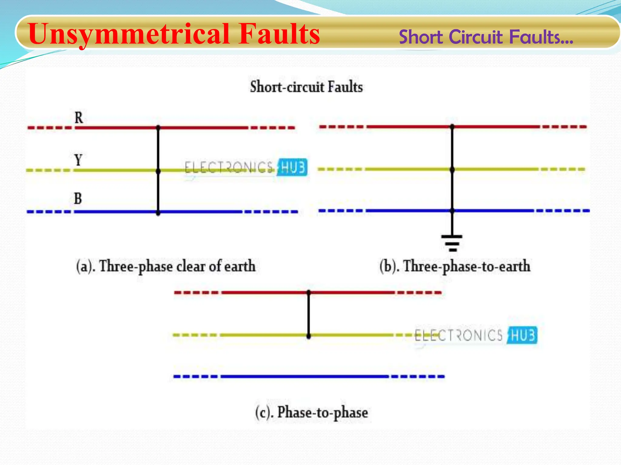
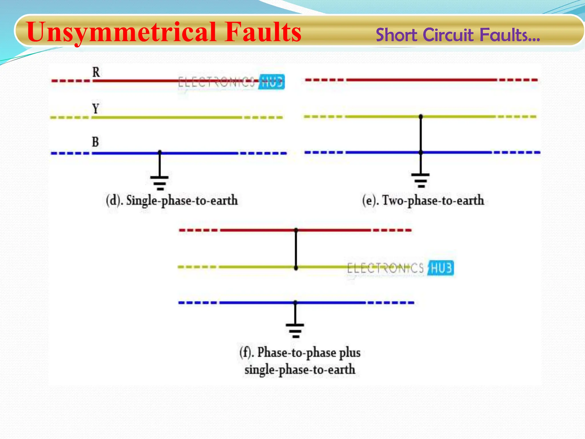
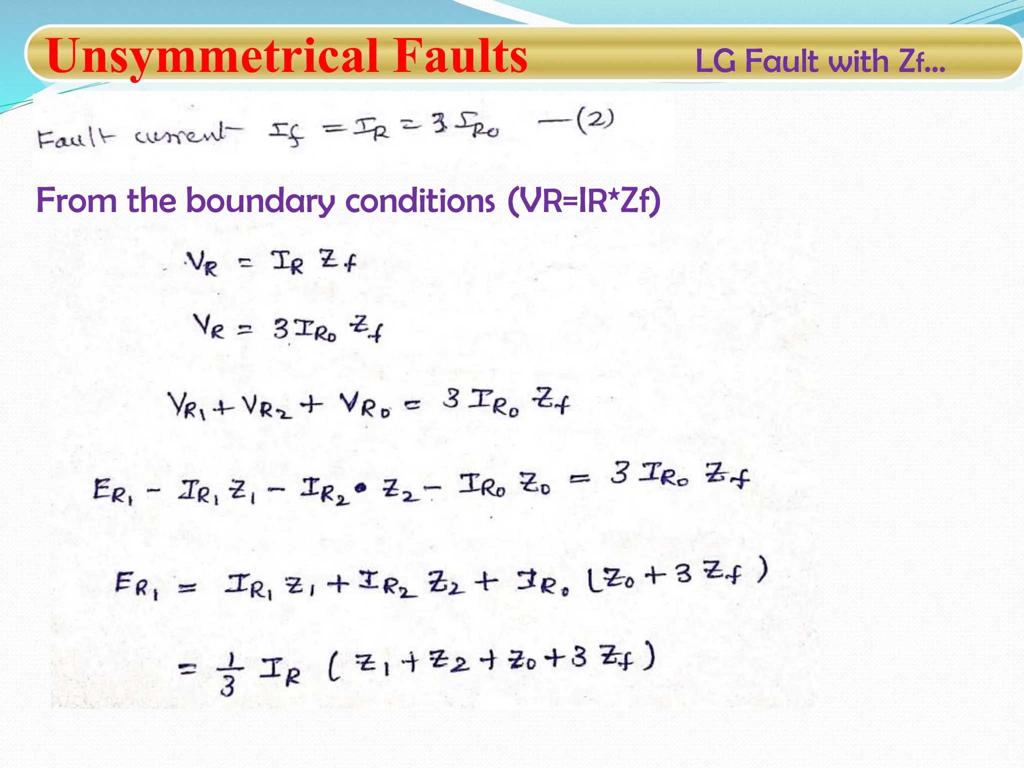
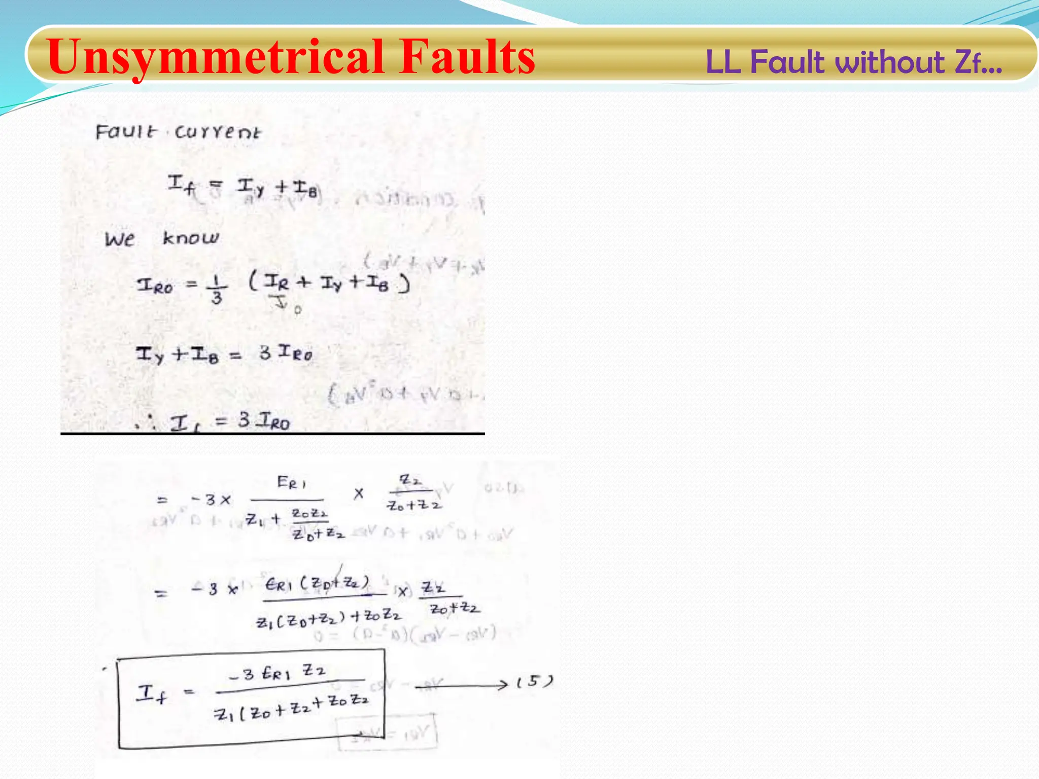
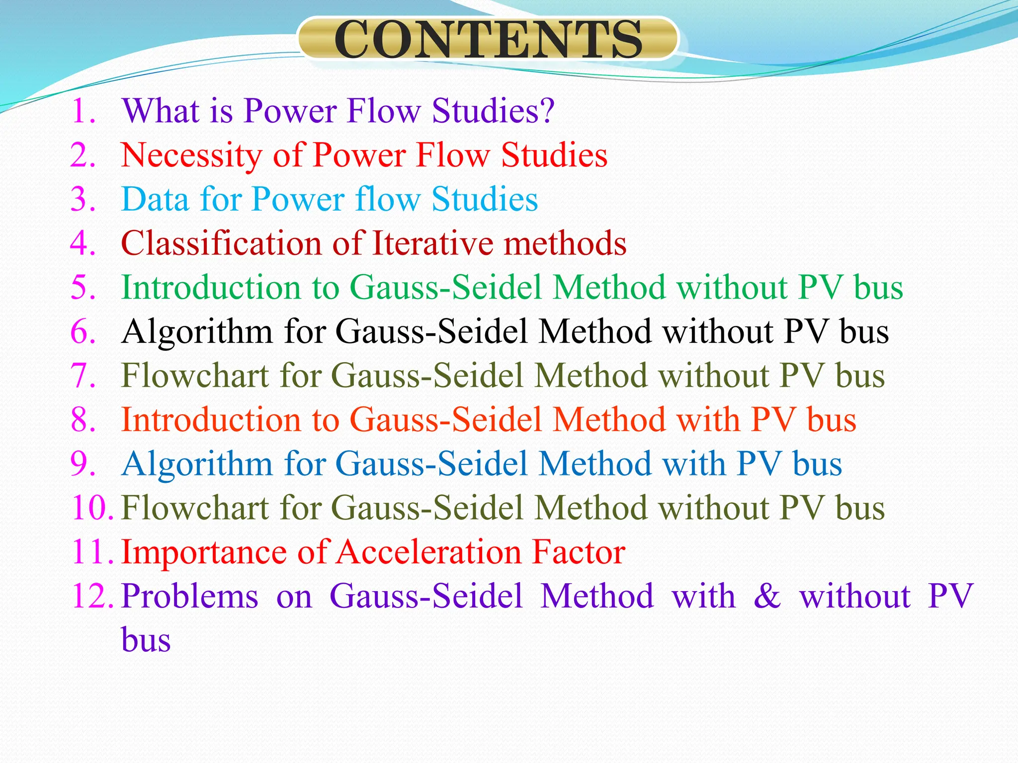
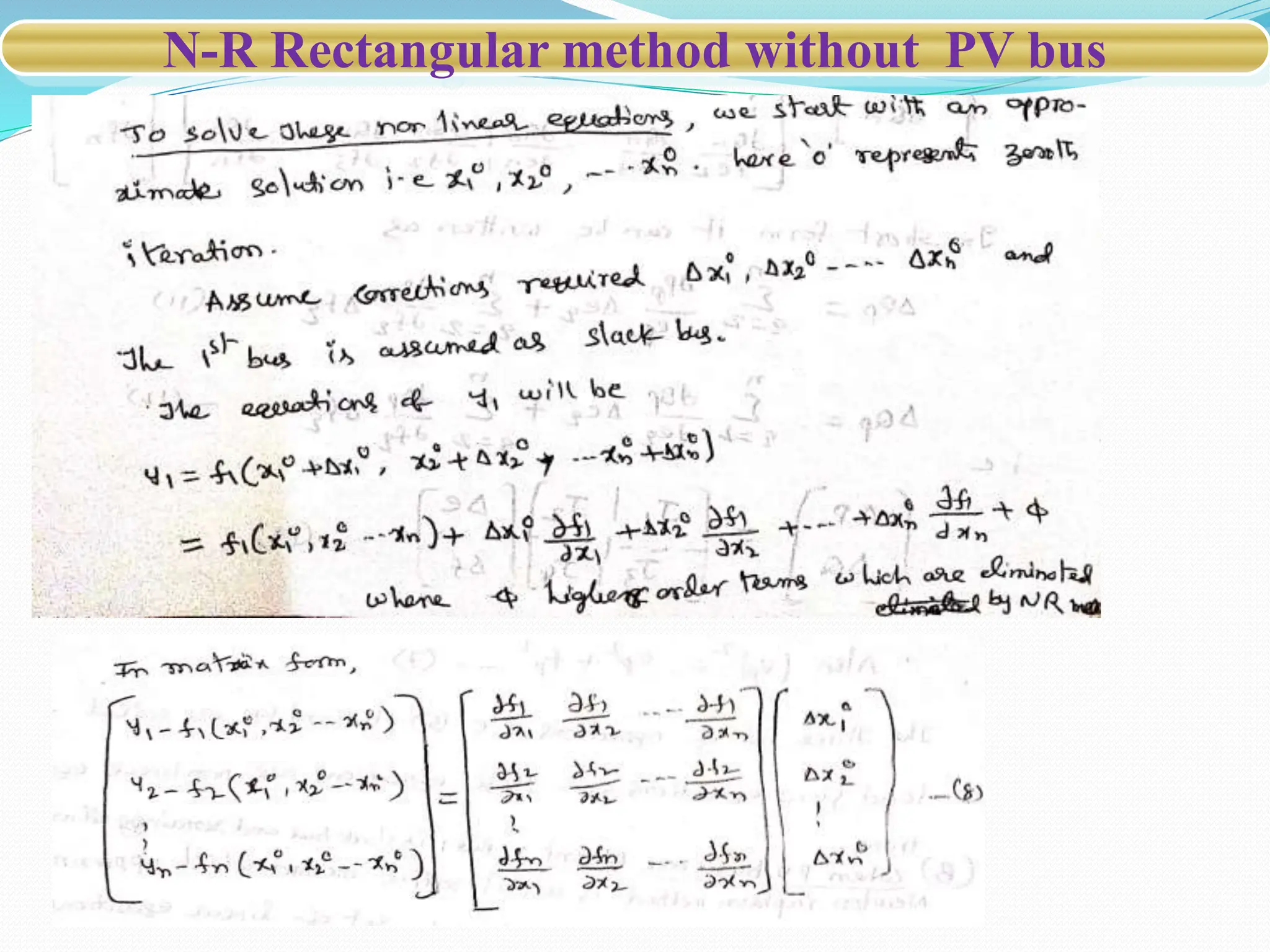
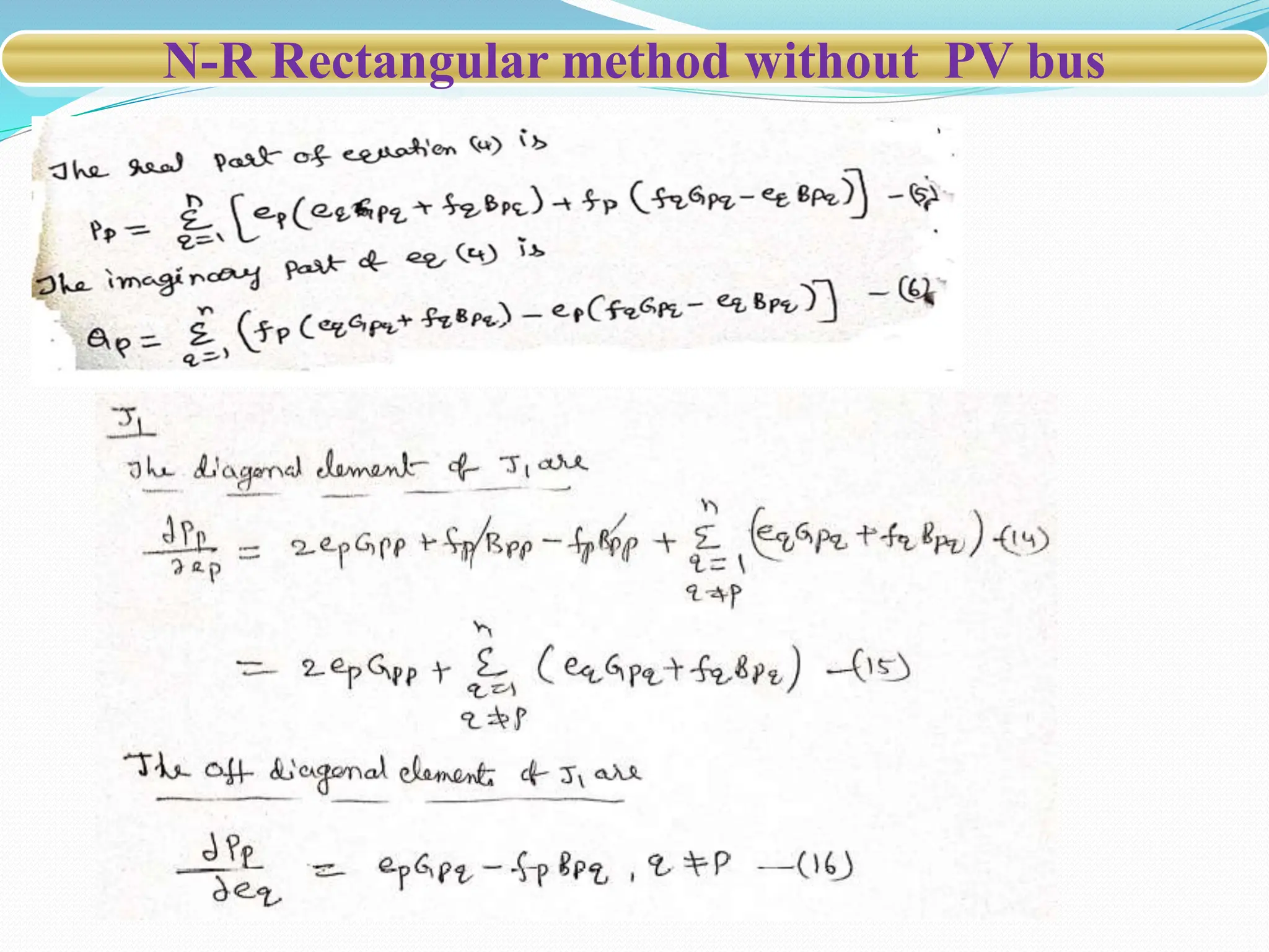
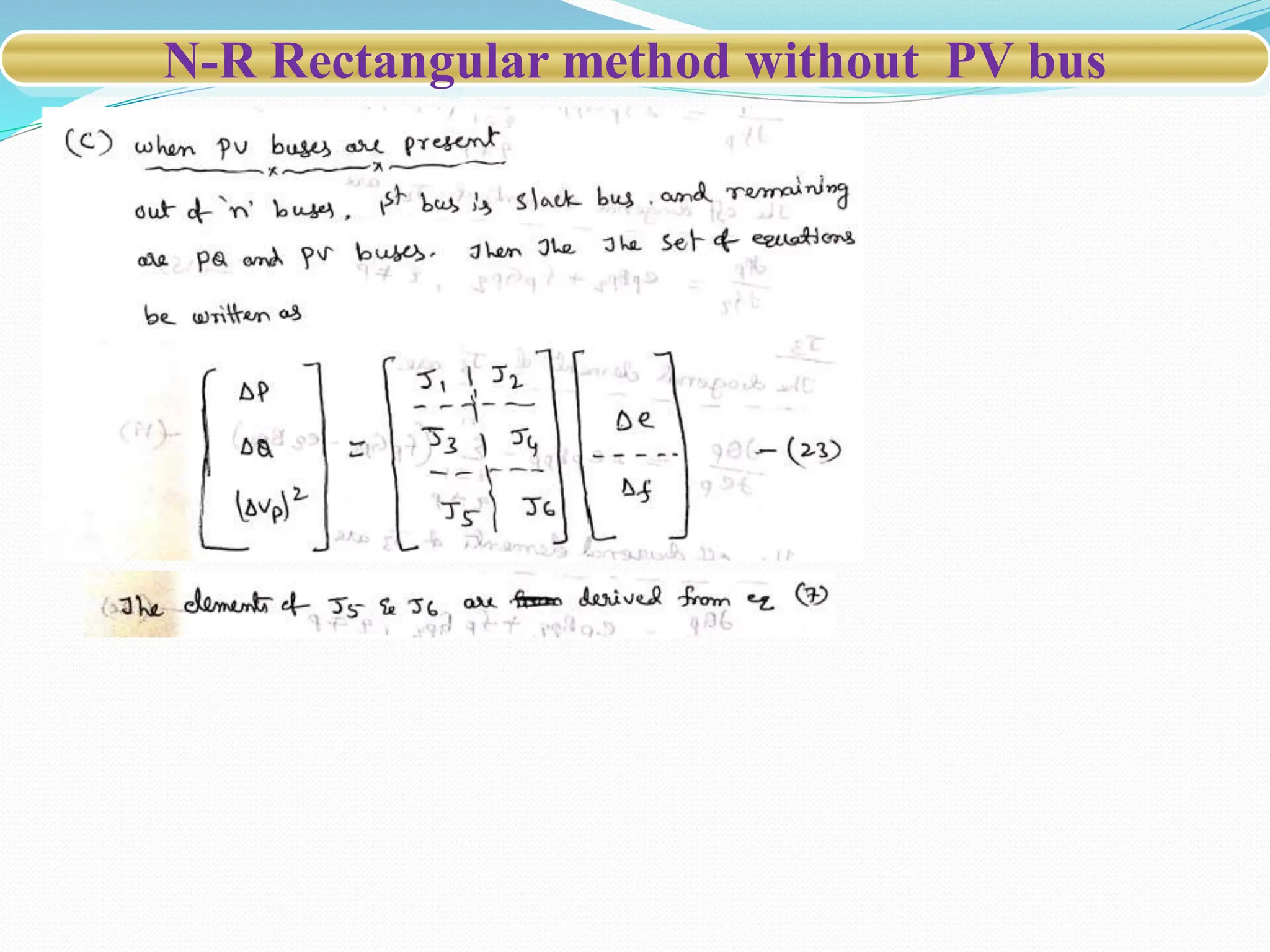
Power System Analysis
(19A02602)
SHORT CIRCUIT STUDIES
By PIDT Baladuraikannan
Assistant Professor
VEMU Institute of Technology
SYLLABUS
Introduction
Now a days Electrical power system is growing in size and
complexity in all sectors such as generation, transmission,
distribution and load systems.
If any fault occurs in power system network which results in
severe economic losses and reduces the reliability of the
electrical system.
Unsymmetrical Faults
Unsymmetrical Faults Introduction …
Under normal or safe operating conditions, the Electric
equipments in a power system network operates at normal
voltage and current ratings
Unsymmetrical Faults Introduction …
• Once the Fault occurs in a power system, voltage and
current values deviates from their nominal ranges.
• A Fault in an electric power system can be defined as , any
abnormal condition of the system that involves the electrical
failure of the equipment, such as , transformers, generators,
bus bars, etc.
General causes of Power System Faults:
•The causes of faults are numerous, e.g. 1. Lightning 2. Heavy
winds 3. Trees falling across lines 4. Vehicles colliding with
towers or poles 5. Birds shorting lines 6. Aircraft colliding with
lines 7. Vandalism (Intentionally damaging property of other
people 8. Small animals entering switchgear 9. Line breaks
due to excessive loading.
Unsymmetrical Faults Introduction …
Additional Causes of Electrical Faults
• Weather conditions: It includes lighting strikes, heavy rains, heavy winds,
salt deposition on overhead lines and conductors, snow and ice accumulation
on transmission lines, etc. These environmental conditions interrupt the power
supply and also damage electrical installations.
• Equipment failures: Various electrical equipments like generators, motors,
transformers, reactors, switching devices, etc causes short circuit faults due to
malfunctioning, ageing, insulation failure of cables and winding. These failures
result in high current to flow through the devices or equipment which further
damages it.
• Human errors: Electrical faults are also caused due to human errors such as
selecting improper rating of equipment or devices, forgetting metallic or
electrical conducting parts after servicing or maintenance, switching the circuit
while it is under servicing, etc.
Smoke of fires: Ionization of air, due to smoke particles, surrounding the
overhead lines results in spark between the lines or between conductors to
insulator. This flashover causes insulators to lose their insulting capacity due to
high voltage.
Unsymmetrical Faults Introduction …
Effects of Power System Faults:
 Over current flow: When fault occurs it creates a very low impedance path
for the current flow. This results in a very high current being drawn from the
supply, causing tripping of relays, damaging insulation and components of the
equipments.
• Danger to operating personnel: Fault occurrence can also cause shocks to
individuals. Severity of the shock depends on the current and voltage at fault
location and even may lead to death.
• Loss of equipment: Heavy current due to short circuit faults result in the
components being burnt completely which leads to improper working of
equipment or device. Sometimes heavy fire causes complete burnout of the
equipments.
• Disturbs interconnected active circuits: Faults not only affect the
location at which they occur but also disturbs the active interconnected circuits
to the faulted line.
• Electrical fires: Short circuit causes flashovers and sparks due to the
ionization of air between two conducting paths which further leads to fire as
we often observe in news such as building and shopping complex fires.
Unsymmetrical Faults Introduction …
Unsymmetrical Faults TYPES
TYPES OF FAULTS:
• Electrical faults in three-phase power system mainly
classified into two types
1. Open circuit faults
2. Short circuit faults
1. Open circuit faults:
- Open circuit faults are also called as series faults
- These faults occur due to the failure of one or more
conductors.
- The figure shows the open circuit faults for single, two
and three phases (or conductors) open condition.
Unsymmetrical Faults Open circuit faults
Effects:
- Abnormal operation of the system
- Danger to the personnel as well as animals
- Exceeding the voltages beyond normal values in certain
parts of the network, which further leads to insulation failures
and developing of short circuit faults.
Unsymmetrical Faults Short Circuit Faults…
2. Short Circuit Faults:
-A short circuit can be defined as an abnormal connection of
very low impedance between two points of different
potential, whether made intentionally or accidentally.
- Short circuit faults are also called as shunt faults.
-These are the most common and severe kind of faults,
resulting in the flow of abnormal high currents through the
equipment or transmission lines.
-If these faults are allowed to persist even for a short period,
it leads to the extensive damage to the equipment
Unsymmetrical Faults Short Circuit Faults…
Effects of Short Circuit Faults:
-These faults are caused due to the insulation failure
between phase conductors or between earth and phase
conductors or both.
-Types of Short Circuit Faults:
- The various possible short circuit fault conditions include
three phase to earth, three phase clear of earth, phase to
phase, single phase to earth, two phase to earth and phase
to phase plus single phase to earth
Unsymmetrical Faults Short Circuit Faults…
Causes
These may be due to internal or external effects
Internal effects include breakdown of transmission lines or
equipment, aging of insulation, deterioration of insulation in
generator, transformer and other electrical equipments,
improper installations and inadequate design.
External effects include overloading of equipments, insulation
failure due to lighting surges and mechanical damage by
public.
Unsymmetrical Faults Short Circuit Faults…
Effects
Arcing faults can lead to fire and explosion in equipments
such as transformers and circuit breakers.
Abnormal currents cause the equipments to get overheated,
which further leads to reduction of life span of their
insulation.
The operating voltages of the system can go below or above
their acceptance values that creates harmful effect to the
service rendered by the power system.
The power flow is severely restricted or even completely
blocked as long as the short circuit fault persists.
Unsymmetrical Faults Shunt Fault typese…
Types of Shunt Faults:
Shunt Faults are classified into two types
1. Unsymmetrical faults.
A) Three phase fault(LLL)
B) Three phase to ground fault (LLLG)
2. Symmetrical faults.
A) LG
B) LL
C) LLG
Unsymmetrical Faults Shunt Fault typese…
Types of Shunt Faults:
Shunt Faults are classified into two types
1. Symmetrical faults:
- These are very severe faults and occur infrequently in the
power systems. These are also called as balanced faults.
- Only 2-5 percent of system faults are symmetrical faults. If
these faults occur, system remains balanced but results in
severe damage to the electrical power system equipments.
- These are two types
A) Three phase fault(LLL)
B) Three phase to ground fault (LLLG)
Unsymmetrical Faults Shunt Fault typese…
2. Unsymmetrical faults:
- These are very common and less severe than symmetrical
faults.
- These are also called unbalanced faults since their occurrence
causes unbalance in the system. Unbalance of the system
means that that impedance values are different in each phase
causing unbalance current to flow in the phases.
- These are three types
A) LG
B) LL
C) LLG
Unsymmetrical Faults Shunt Fault typese…
Unsymmetrical faults:
- In the analysis of Unsymmetrical faults, the following points
are very important.
- 1. The Generated EMF is of positive sequence only
- 2. No current flow in the network other than due to fault
- 3. Phase R shall be taken as reference phase.
- 4. In each case of Unsymmetrical faults, EMF’s per phases are
denoted by ER, EY and EB and the line voltage per phase are
VR, VY and VB.
Unsymmetrical Faults Shunt Fault typese…
1. Line to ground (L-G) Fault
- Line to ground fault (L-G) is most common fault and 65-70
percent of faults are of this type.
- These are two types
- A) LG without fault impedance
- B) LG with fault impedance
Unsymmetrical Faults LG Fault without Zf…
1. Line to ground (L-G) Fault without Fault Impedance(Zf)
Unsymmetrical Faults LG Fault without Zf…
From the boundary conditions (IY=0 and IB=0)
Unsymmetrical Faults LG Fault without Zf…
From the boundary conditions (VR=0)
Unsymmetrical Faults LG Fault with Zf…
2. Line to ground (L-G) Fault with Fault Impedance(Zf)
Unsymmetrical Faults LG Fault with Zf…
From the boundary conditions (IY=0 and IB=0)
Unsymmetrical Faults LG Fault with Zf…
From the boundary conditions (VR=IR*Zf)
Unsymmetrical Faults LG Fault with Zf…
Unsymmetrical Faults LL Fault without Zf…
1. Line to Line (L-L) Fault without Fault Impedance(Zf)
Unsymmetrical Faults LL Fault without Zf…
Unsymmetrical Faults LL Fault with Zf…
1. Line to Line (L-L) Fault with Fault Impedance(Zf)
Unsymmetrical Faults LL Fault without Zf…
Unsymmetrical Faults LL Fault with Zf…
Unsymmetrical Faults LL-G Fault without Zf…
1. Double Line to Ground (LL-G) Fault without Fault
Impedance(Zf)
Unsymmetrical Faults LL Fault without Zf…
Unsymmetrical Faults LL-G Fault with Zf…
1. Double Line to Ground (LL-G) Fault with Fault
Impedance(Zf)
Unsymmetrical Faults LL-G Fault with Zf…
PSA
III UNIT
POWER FLOW STUDIES -1
SYLLABUS
POWER FLOW STUDIES-I
Necessity of Power Flow Studies – Data for Power Flow
Studies – Derivation of Static Load Flow Equations – Load
Flow Solutions using Gauss Seidel Method: Acceleration
Factor, Load Flow Solution with and without P-V Buses,
Algorithm and Flowchart. Numerical Load flow Solution for
Simple Power Systems (Max. 3-Buses): Determination of Bus
Voltages, Injected Active and Reactive Powers (Sample One
Iteration only) and Finding Line Flows/Losses for the given
Bus Voltages
1. What is Power Flow Studies?
2. Necessity of Power Flow Studies
3. Data for Power flow Studies
4. Classification of Iterative methods
5. Introduction to Gauss-Seidel Method without PV bus
6. Algorithm for Gauss-Seidel Method without PV bus
7. Flowchart for Gauss-Seidel Method without PV bus
8. Introduction to Gauss-Seidel Method with PV bus
9. Algorithm for Gauss-Seidel Method with PV bus
10.Flowchart for Gauss-Seidel Method without PV bus
11.Importance of Acceleration Factor
12.Problems on Gauss-Seidel Method with & without PV
bus
CONTENTS
 It is also known as Load flow study .
 Power flow study is defined as the Study or monitoring of
power flow in the power system network and to obtain the
steady state operation.
 Power flow analysis is the most important and essential
approach to investigating the problems in power system
operation and planning .
 Load flow study is a bread and butter for any power system
engineer or electric energy system engineer.
 In fact, It gives you pulse of the system, what is happening in
the system that is given by load flow studies.
1.What is Power Flow Studies?
 It is a numerical analysis of the power flow in an
interconnected system.
 It is defined as the Study of set of non linear algebraic
equations of the power system network for the
purpose of to obtain
- Magnitude of Voltage (V)
- Phase angle of voltage (δ)
- Real Power (P) and
- Reactive Power (Q)
1.What is Power Flow Studies? Contd..
 The various steps involved in power flow study are as
follows
1. Modelling of power system network.
2. Representation of modelled network using non linear
algebraic equations.
3. Solving of non linear algebraic equations using iterative
techniques.
1.What is Load Flow Studies? Contd…
 It helps in continues monitoring of current state of the system.
 The Power flow studies involves the solution of the power system
network under steady state operation subjected to certain
inequality constraints under which the system operates.
 These constraints are in the form of load node voltages, reactive
power generation of the generators, the tap settings of tap
changing transformers under load etc.
 C:UsersdellDesktopcircuit.pdf
 From the line flow we can also determine the over and under load
conditions.
 It helps in System loss minimization and transformer tap setting for
economic operation.
2.Necessity of Power Flow Studies?
 It is required for Planning, Operation, Economic Scheduling &
Exchange of power b/w utilities .
 Whether you do power study, stability study, economic operation
this load flow study is very important.
 To analyze the effectiveness of alternative plans for future system
expansion to meet the increased load demand.
 To determine the best location for capacitors or voltage regulators
for improvement of voltage regulation.
 It helps in designing a new power system network.
 The load flow studies are required at various stages of transient or
dynamic stability analysis.
2.Necessity of Power Flow Studies?
Load flow analysis can provide a balanced steady state operation of the
power system, without considering system transient processes. Hence, the
mathematic model of load flow problem is a nonlinear algebraic equations
without differential equations.
The main objective of the Power flow studies to determine the Voltage
magnitude and phase angle of voltages at each bus, real and reactive power
injected at busses and also real and reactive power flows over transmission lines
in the steady state by solving nonlinear algebraic equations.
2.Necessity of Load Flow Studies? Contd…
 Load flow is nothing but the steady state of the power
system network.
It is the Study of set of non linear algebraic equations of the
power system network for the purpose of to obtain (or) The data
obtained from the load flow studies are
1. The magnitude of the voltage (V)
2. Phase angle of the voltage (δ)
3. Active power (P)
4. Reactive power (Q) flow on transmission lines.
 At any bus, Out of these four quantities two quantities
are specified and remaining two quantities are to be
determined giving rise to three types of busses.
3. Data for Load Flow Studies?
 Classification of buses
There are three types of buses
1. Slack bus
2. Load bus
3. Generator bus
Slack bus
Slack is also called as reference bus to meet the power balance
condition i.e provide power mismatch between generation and
load plus losses.
Slack bus is usually identified as bus 1.
The known(Specified) variables on this bus is |V| and δ and the
determined variables are P and Q.
3. Data forLoad Flow Studies?
Load bus
 It is also called as PQ bus or non-generator bus
This non-generator bus which can be obtained from historical data records,
measurement or forecast.
The consumer power is met at this bus.
the real and reactive power supply to a power system are defined to be
positive, while the power consumed in a power system are defined to be
negative.
At this bus, P and Q are specified and the |V| and δ are to be determined by
solving load flow equations.
3. Data for Load Flow Studies?
Generator bus
 It is also called as voltage controlled bus or PV bus
This Generator bus is connected to generator unit in which Output active
power is controlled by prime mover and voltage can be controlled by adjusting
the excitation of the generator.
The known variable in this bus is P and |V| and the unknown is Q and δ
In this generator bus, there must be limits for Q (Ex : 3 ≤Q ≤ 2 MVAR )
3. Data for Load Flow Studies?
 Summery on Classification of buses ( V, δ, P and Q)
3. Data for Load Flow Studies?
3. Static Load Flow Studies?
..PSA previous year qp13A02604062017.pdf
..PSA previous year qp15A02603062018.pdf
3. Static Load Flow Equations? Contd..
Methods of solving static load flow equations
 The different methods for load flow solutions are
1. Gauss method
2. Gauss Seidel method
3. Newton Raphson method
4. Decoupled method
5. Fast Decoupled method
3. Static Load Flow Studies? Types..
Gauss – Seidel Method:
Gauss Seidel method is one of the common methods employed for solving
power flow equations.
Advantages:
Used for small size system
Simplicity in technique I,e Calculations are simple
Small computer memory requirement i.e Programming task is lesser
Less computational time per iteration
Disadvantages:
Not suitable for larger systems
Slow rate of convergence resulting in larger number of iterations
Increase in the number of iterations with increase in the number of buses
Guass – Seidel Method
3. G-S without PV bus
3. G-S without PV bus contd…
G-S REFERENCE.pdf
3. G-S without PV bus contd…
3. Algorithm for G-S without PV bus
SUMMERY
3. Flowchart for G-S without PV bus
C:UsersdellDesktopGS WITHOUT PV BUS.pdf
3. Flowchart for G-S without PV bus
 PROBLEM ON G-S WITHOUT PV BUS.pdf
Problem on G-S without PV bus
3. Introduction to G-S with PV bus
 For PQ bus
3. Introduction to G-S with PV bus
3. Algorithm for G-S with PV bus
3. Algorithm for G-S with PV bus Contd…
3. Flowchart for G-S with PV bus
3. Acceleration factor
Problems
Problems
Problems
Problems
Problems
Problems
Problems
Carry out the load flow solution using G.S method upto one iteration.taking 1st bus as
slack bus
Problems
Given data is
Problems
Problems
Problems
Problems
Problems
Problems
Problems
Problems
Problems
Problems
Problems
Problems
Problems
Problems
Problems
PSA
IV UNIT
POWER FLOW STUDIES -2
SYLLABUS
POWER FLOW STUDIES-II
Newton Raphson Method in Rectangular and Polar Co-
Ordinates Form: Load Flow Solution with or without PV
Buses- Derivation of Jacobian Elements, Algorithm and
Flowchart. Decoupled and Fast Decoupled Methods.-
Comparison of Different Methods – DC Load Flow
1.Newton Raphson Method
N-R Rectangular Method
N-R Rectangular method without PV bus
IV UNITNR RECTANGULARAlgorithm for NR
WITHOUT PV rectangular.pdf
N-R Rectangular method without PV bus
IV UNITNR RECTANGULARNR Flowchart without pv bus
(RECTA).pdf
N-R Rectangular method with PV bus
IV UNITNR RECTANGULARAlgorithm for NR rec with
PV.pdf
N-R Rectangular method with PV bus (Flowchart)
IV UNITNR RECTANGULARFlowchart for NR rec with
PV.pdf
N-R Polar Coordinates method
N-R Polar Coordinates method without PV bus
N-R Polar Algorithm without PV bus
IV UNITNR POLARAlgorithm for NR without pv
(Polar).pdf
N-R Polar Flowchart without PV bus
IV UNITNR POLARNR flowchart without pv(polar).pdf
N-R Polar method with PV bus
N-R Polar Algorithm with PV bus
IV UNITNR POLARAlgorithm for NR with pv polar.pdf
N-R Polar Flowchart with PV bus
IV UNITNR POLARFlowchart for NR with pv polar.pdf
DLF and FDLF
IV UNITDLF and FDLF methods.pdf
Advantages of FDLF
Disadvantages of FDLF
Comparison of different load flow methods
 IV UNITcomparision methods.pdf
Comparison of different load flow methods
PSA
V UNIT
POWER SYSTEM STABILITY
ANALYSIS
SYLLABUS
POWER SYSTEM STABILITY ANALYSIS
Elementary Concepts of Steady State, Dynamic and Transient
Stabilities - Description of: Steady State Stability Power Limit,
Transfer Reactance, Synchronizing Power Coefficient, Power
Angle Curve and Determination of Steady State Stability
and Methods to Improve Steady State Stability - Derivation of
Swing Equation - Determination of Transient Stability by Equal
Area Criterion, Application of Equal Area Criterion, Critical
Clearing Angle Calculation. Solution of Swing Equation by 4th
Order Runga Kutta Method (up to 2 iterations) - Methods to
improve Stability - Application of Auto Reclosing and Fast
Operating Circuit Breakers.
1. Elementary Concepts of Stability
1. Elementary concepts of Stability
Derivation of SSS.pdf
Derivation of Steady State Stability
Methods to improve SSS
Power Angle Curve
Power Angle Curve
Power Angle Curve
Power Angle Curve
Transfer Reactance
Transfer Reactance
Synchronizing Power Coefficient
problem on spc.pdf
Synchronizing Power Coefficient
Methods to improve SSS
SWING EQUATION
SWING EQUATION
SWING EQUATION
SWING EQUATION
SWING EQUATION
4. Determination of Critical Clearing Angle Calculation
Applications of Equal Area Criterion
Factors Affecting Transient Stability
Discuss the various factors that affects the transient
stability of a power system.
Factors affecting transient stability :-
i) Prime mover input torque
ii) Inertia of prime mover and generator
iii) Inertia of motor and shaft load.
iv) Shaft load output torque
v) Internal voltages of synchronous generators
vi) Reactance of the system including generator,
motor and line etc,.
vii) internal voltage of motor.
Methods to Improve Transient Stability
Methods to improve transient stability:-
•Increase of system voltages:-It increases the value of
maximum power and transient stability.
•Use of high speed excitation systems:-It increases the value of
generated voltage which leads to increase in maximum power
and transient stability.
•Use of high speed governors:-which can quickly adjust
generator input to load.
•Use of high speed circuit breakers:- It reduces the severity of
faults and protects against the lightning which leads to
increase in transient stability.
Methods to Improve Transient Stability
Methods to improve transient stability:-
Use of auto-reclosers:-
Automatic reclosing of circuit breakers are known as auto-reclosers
or auto-reclosing. Most of the faults (About 80-90% ) on
transmission and distribution lines are transient in nature and are
self- clearing. By auto-reclosing and rapid switching, the fault is
isolated as fast as in 2 cycles and then the circuit breaker reclosers
after a suitable time interval. Auto-reclosers increase the
decelerating area and transient stability.
Use of automatic voltage regulators:-
If the excitation system is controlled by an automatic voltage
regulator, then the voltage regulator controls the field current and
generated voltage which leads to increase in maximum power and
transient stability.
Applications of Equal Area Criterion
•Reduction of transfer reactance:-It increases the value of
maximum power and transient stability.
•Use of breaking resistors:- Breaking resistor is connected at
or near the generator bus for stability improvement where
large load is suddenly lost or clearing is delayed
•Load shedding:- It is applied for distribution systems or
major industrial loads. Load shedding reduces the losses and
increases the stability.
•Bypass valving:-In this method, stability of the system can
be increased by by decreasing the mechanical input to the
tubine.
•Use of high inertia machines.
•Use of HVDC Links .
•Use of switching of series capacitors.
Methods to Improve Transient Stability
Applications of Equal Area Criterion
• V UNIT PSSRK Method 4th Order.pdf
R K Method

15_02_2023_415559293.pdf power system analysis

  • 1.
    Power System Analysis (19A02602) SHORTCIRCUIT STUDIES By PIDT Baladuraikannan Assistant Professor VEMU Institute of Technology
  • 2.
  • 3.
    Introduction Now a daysElectrical power system is growing in size and complexity in all sectors such as generation, transmission, distribution and load systems. If any fault occurs in power system network which results in severe economic losses and reduces the reliability of the electrical system. Unsymmetrical Faults
  • 4.
    Unsymmetrical Faults Introduction… Under normal or safe operating conditions, the Electric equipments in a power system network operates at normal voltage and current ratings
  • 5.
    Unsymmetrical Faults Introduction… • Once the Fault occurs in a power system, voltage and current values deviates from their nominal ranges. • A Fault in an electric power system can be defined as , any abnormal condition of the system that involves the electrical failure of the equipment, such as , transformers, generators, bus bars, etc. General causes of Power System Faults: •The causes of faults are numerous, e.g. 1. Lightning 2. Heavy winds 3. Trees falling across lines 4. Vehicles colliding with towers or poles 5. Birds shorting lines 6. Aircraft colliding with lines 7. Vandalism (Intentionally damaging property of other people 8. Small animals entering switchgear 9. Line breaks due to excessive loading.
  • 6.
    Unsymmetrical Faults Introduction… Additional Causes of Electrical Faults • Weather conditions: It includes lighting strikes, heavy rains, heavy winds, salt deposition on overhead lines and conductors, snow and ice accumulation on transmission lines, etc. These environmental conditions interrupt the power supply and also damage electrical installations. • Equipment failures: Various electrical equipments like generators, motors, transformers, reactors, switching devices, etc causes short circuit faults due to malfunctioning, ageing, insulation failure of cables and winding. These failures result in high current to flow through the devices or equipment which further damages it. • Human errors: Electrical faults are also caused due to human errors such as selecting improper rating of equipment or devices, forgetting metallic or electrical conducting parts after servicing or maintenance, switching the circuit while it is under servicing, etc. Smoke of fires: Ionization of air, due to smoke particles, surrounding the overhead lines results in spark between the lines or between conductors to insulator. This flashover causes insulators to lose their insulting capacity due to high voltage.
  • 7.
    Unsymmetrical Faults Introduction… Effects of Power System Faults:  Over current flow: When fault occurs it creates a very low impedance path for the current flow. This results in a very high current being drawn from the supply, causing tripping of relays, damaging insulation and components of the equipments. • Danger to operating personnel: Fault occurrence can also cause shocks to individuals. Severity of the shock depends on the current and voltage at fault location and even may lead to death. • Loss of equipment: Heavy current due to short circuit faults result in the components being burnt completely which leads to improper working of equipment or device. Sometimes heavy fire causes complete burnout of the equipments. • Disturbs interconnected active circuits: Faults not only affect the location at which they occur but also disturbs the active interconnected circuits to the faulted line. • Electrical fires: Short circuit causes flashovers and sparks due to the ionization of air between two conducting paths which further leads to fire as we often observe in news such as building and shopping complex fires.
  • 8.
  • 9.
    Unsymmetrical Faults TYPES TYPESOF FAULTS: • Electrical faults in three-phase power system mainly classified into two types 1. Open circuit faults 2. Short circuit faults 1. Open circuit faults: - Open circuit faults are also called as series faults - These faults occur due to the failure of one or more conductors. - The figure shows the open circuit faults for single, two and three phases (or conductors) open condition.
  • 10.
  • 11.
    Unsymmetrical Faults Opencircuit faults Effects: - Abnormal operation of the system - Danger to the personnel as well as animals - Exceeding the voltages beyond normal values in certain parts of the network, which further leads to insulation failures and developing of short circuit faults.
  • 12.
    Unsymmetrical Faults ShortCircuit Faults… 2. Short Circuit Faults: -A short circuit can be defined as an abnormal connection of very low impedance between two points of different potential, whether made intentionally or accidentally. - Short circuit faults are also called as shunt faults. -These are the most common and severe kind of faults, resulting in the flow of abnormal high currents through the equipment or transmission lines. -If these faults are allowed to persist even for a short period, it leads to the extensive damage to the equipment
  • 13.
    Unsymmetrical Faults ShortCircuit Faults… Effects of Short Circuit Faults: -These faults are caused due to the insulation failure between phase conductors or between earth and phase conductors or both. -Types of Short Circuit Faults: - The various possible short circuit fault conditions include three phase to earth, three phase clear of earth, phase to phase, single phase to earth, two phase to earth and phase to phase plus single phase to earth
  • 14.
    Unsymmetrical Faults ShortCircuit Faults…
  • 15.
    Unsymmetrical Faults ShortCircuit Faults…
  • 16.
    Unsymmetrical Faults ShortCircuit Faults… Causes These may be due to internal or external effects Internal effects include breakdown of transmission lines or equipment, aging of insulation, deterioration of insulation in generator, transformer and other electrical equipments, improper installations and inadequate design. External effects include overloading of equipments, insulation failure due to lighting surges and mechanical damage by public.
  • 17.
    Unsymmetrical Faults ShortCircuit Faults… Effects Arcing faults can lead to fire and explosion in equipments such as transformers and circuit breakers. Abnormal currents cause the equipments to get overheated, which further leads to reduction of life span of their insulation. The operating voltages of the system can go below or above their acceptance values that creates harmful effect to the service rendered by the power system. The power flow is severely restricted or even completely blocked as long as the short circuit fault persists.
  • 18.
    Unsymmetrical Faults ShuntFault typese… Types of Shunt Faults: Shunt Faults are classified into two types 1. Unsymmetrical faults. A) Three phase fault(LLL) B) Three phase to ground fault (LLLG) 2. Symmetrical faults. A) LG B) LL C) LLG
  • 19.
    Unsymmetrical Faults ShuntFault typese… Types of Shunt Faults: Shunt Faults are classified into two types 1. Symmetrical faults: - These are very severe faults and occur infrequently in the power systems. These are also called as balanced faults. - Only 2-5 percent of system faults are symmetrical faults. If these faults occur, system remains balanced but results in severe damage to the electrical power system equipments. - These are two types A) Three phase fault(LLL) B) Three phase to ground fault (LLLG)
  • 20.
    Unsymmetrical Faults ShuntFault typese… 2. Unsymmetrical faults: - These are very common and less severe than symmetrical faults. - These are also called unbalanced faults since their occurrence causes unbalance in the system. Unbalance of the system means that that impedance values are different in each phase causing unbalance current to flow in the phases. - These are three types A) LG B) LL C) LLG
  • 21.
    Unsymmetrical Faults ShuntFault typese… Unsymmetrical faults: - In the analysis of Unsymmetrical faults, the following points are very important. - 1. The Generated EMF is of positive sequence only - 2. No current flow in the network other than due to fault - 3. Phase R shall be taken as reference phase. - 4. In each case of Unsymmetrical faults, EMF’s per phases are denoted by ER, EY and EB and the line voltage per phase are VR, VY and VB.
  • 22.
    Unsymmetrical Faults ShuntFault typese… 1. Line to ground (L-G) Fault - Line to ground fault (L-G) is most common fault and 65-70 percent of faults are of this type. - These are two types - A) LG without fault impedance - B) LG with fault impedance
  • 23.
    Unsymmetrical Faults LGFault without Zf… 1. Line to ground (L-G) Fault without Fault Impedance(Zf)
  • 24.
    Unsymmetrical Faults LGFault without Zf… From the boundary conditions (IY=0 and IB=0)
  • 25.
    Unsymmetrical Faults LGFault without Zf… From the boundary conditions (VR=0)
  • 26.
    Unsymmetrical Faults LGFault with Zf… 2. Line to ground (L-G) Fault with Fault Impedance(Zf)
  • 27.
    Unsymmetrical Faults LGFault with Zf… From the boundary conditions (IY=0 and IB=0)
  • 28.
    Unsymmetrical Faults LGFault with Zf… From the boundary conditions (VR=IR*Zf)
  • 29.
    Unsymmetrical Faults LGFault with Zf…
  • 30.
    Unsymmetrical Faults LLFault without Zf… 1. Line to Line (L-L) Fault without Fault Impedance(Zf)
  • 31.
    Unsymmetrical Faults LLFault without Zf…
  • 32.
    Unsymmetrical Faults LLFault without Zf…
  • 33.
    Unsymmetrical Faults LLFault without Zf…
  • 34.
    Unsymmetrical Faults LLFault without Zf…
  • 35.
    Unsymmetrical Faults LLFault with Zf… 1. Line to Line (L-L) Fault with Fault Impedance(Zf)
  • 36.
    Unsymmetrical Faults LLFault without Zf…
  • 37.
    Unsymmetrical Faults LLFault with Zf…
  • 38.
    Unsymmetrical Faults LLFault with Zf…
  • 39.
    Unsymmetrical Faults LLFault with Zf…
  • 40.
    Unsymmetrical Faults LL-GFault without Zf… 1. Double Line to Ground (LL-G) Fault without Fault Impedance(Zf)
  • 41.
    Unsymmetrical Faults LLFault without Zf…
  • 42.
    Unsymmetrical Faults LLFault without Zf…
  • 43.
    Unsymmetrical Faults LL-GFault with Zf… 1. Double Line to Ground (LL-G) Fault with Fault Impedance(Zf)
  • 44.
    Unsymmetrical Faults LL-GFault with Zf…
  • 45.
    Unsymmetrical Faults LL-GFault with Zf…
  • 46.
    Unsymmetrical Faults LL-GFault with Zf…
  • 47.
    Unsymmetrical Faults LL-GFault with Zf…
  • 48.
  • 49.
    SYLLABUS POWER FLOW STUDIES-I Necessityof Power Flow Studies – Data for Power Flow Studies – Derivation of Static Load Flow Equations – Load Flow Solutions using Gauss Seidel Method: Acceleration Factor, Load Flow Solution with and without P-V Buses, Algorithm and Flowchart. Numerical Load flow Solution for Simple Power Systems (Max. 3-Buses): Determination of Bus Voltages, Injected Active and Reactive Powers (Sample One Iteration only) and Finding Line Flows/Losses for the given Bus Voltages
  • 50.
    1. What isPower Flow Studies? 2. Necessity of Power Flow Studies 3. Data for Power flow Studies 4. Classification of Iterative methods 5. Introduction to Gauss-Seidel Method without PV bus 6. Algorithm for Gauss-Seidel Method without PV bus 7. Flowchart for Gauss-Seidel Method without PV bus 8. Introduction to Gauss-Seidel Method with PV bus 9. Algorithm for Gauss-Seidel Method with PV bus 10.Flowchart for Gauss-Seidel Method without PV bus 11.Importance of Acceleration Factor 12.Problems on Gauss-Seidel Method with & without PV bus CONTENTS
  • 51.
     It isalso known as Load flow study .  Power flow study is defined as the Study or monitoring of power flow in the power system network and to obtain the steady state operation.  Power flow analysis is the most important and essential approach to investigating the problems in power system operation and planning .  Load flow study is a bread and butter for any power system engineer or electric energy system engineer.  In fact, It gives you pulse of the system, what is happening in the system that is given by load flow studies. 1.What is Power Flow Studies?
  • 52.
     It isa numerical analysis of the power flow in an interconnected system.  It is defined as the Study of set of non linear algebraic equations of the power system network for the purpose of to obtain - Magnitude of Voltage (V) - Phase angle of voltage (δ) - Real Power (P) and - Reactive Power (Q) 1.What is Power Flow Studies? Contd..
  • 53.
     The varioussteps involved in power flow study are as follows 1. Modelling of power system network. 2. Representation of modelled network using non linear algebraic equations. 3. Solving of non linear algebraic equations using iterative techniques. 1.What is Load Flow Studies? Contd…
  • 54.
     It helpsin continues monitoring of current state of the system.  The Power flow studies involves the solution of the power system network under steady state operation subjected to certain inequality constraints under which the system operates.  These constraints are in the form of load node voltages, reactive power generation of the generators, the tap settings of tap changing transformers under load etc.  C:UsersdellDesktopcircuit.pdf  From the line flow we can also determine the over and under load conditions.  It helps in System loss minimization and transformer tap setting for economic operation. 2.Necessity of Power Flow Studies?
  • 55.
     It isrequired for Planning, Operation, Economic Scheduling & Exchange of power b/w utilities .  Whether you do power study, stability study, economic operation this load flow study is very important.  To analyze the effectiveness of alternative plans for future system expansion to meet the increased load demand.  To determine the best location for capacitors or voltage regulators for improvement of voltage regulation.  It helps in designing a new power system network.  The load flow studies are required at various stages of transient or dynamic stability analysis. 2.Necessity of Power Flow Studies?
  • 56.
    Load flow analysiscan provide a balanced steady state operation of the power system, without considering system transient processes. Hence, the mathematic model of load flow problem is a nonlinear algebraic equations without differential equations. The main objective of the Power flow studies to determine the Voltage magnitude and phase angle of voltages at each bus, real and reactive power injected at busses and also real and reactive power flows over transmission lines in the steady state by solving nonlinear algebraic equations. 2.Necessity of Load Flow Studies? Contd…
  • 57.
     Load flowis nothing but the steady state of the power system network. It is the Study of set of non linear algebraic equations of the power system network for the purpose of to obtain (or) The data obtained from the load flow studies are 1. The magnitude of the voltage (V) 2. Phase angle of the voltage (δ) 3. Active power (P) 4. Reactive power (Q) flow on transmission lines.  At any bus, Out of these four quantities two quantities are specified and remaining two quantities are to be determined giving rise to three types of busses. 3. Data for Load Flow Studies?
  • 58.
     Classification ofbuses There are three types of buses 1. Slack bus 2. Load bus 3. Generator bus Slack bus Slack is also called as reference bus to meet the power balance condition i.e provide power mismatch between generation and load plus losses. Slack bus is usually identified as bus 1. The known(Specified) variables on this bus is |V| and δ and the determined variables are P and Q. 3. Data forLoad Flow Studies?
  • 59.
    Load bus  Itis also called as PQ bus or non-generator bus This non-generator bus which can be obtained from historical data records, measurement or forecast. The consumer power is met at this bus. the real and reactive power supply to a power system are defined to be positive, while the power consumed in a power system are defined to be negative. At this bus, P and Q are specified and the |V| and δ are to be determined by solving load flow equations. 3. Data for Load Flow Studies?
  • 60.
    Generator bus  Itis also called as voltage controlled bus or PV bus This Generator bus is connected to generator unit in which Output active power is controlled by prime mover and voltage can be controlled by adjusting the excitation of the generator. The known variable in this bus is P and |V| and the unknown is Q and δ In this generator bus, there must be limits for Q (Ex : 3 ≤Q ≤ 2 MVAR ) 3. Data for Load Flow Studies?
  • 61.
     Summery onClassification of buses ( V, δ, P and Q) 3. Data for Load Flow Studies?
  • 62.
    3. Static LoadFlow Studies? ..PSA previous year qp13A02604062017.pdf ..PSA previous year qp15A02603062018.pdf
  • 63.
    3. Static LoadFlow Equations? Contd..
  • 64.
    3. Static LoadFlow Equations? Contd..
  • 65.
    Methods of solvingstatic load flow equations  The different methods for load flow solutions are 1. Gauss method 2. Gauss Seidel method 3. Newton Raphson method 4. Decoupled method 5. Fast Decoupled method 3. Static Load Flow Studies? Types..
  • 66.
    Gauss – SeidelMethod: Gauss Seidel method is one of the common methods employed for solving power flow equations. Advantages: Used for small size system Simplicity in technique I,e Calculations are simple Small computer memory requirement i.e Programming task is lesser Less computational time per iteration Disadvantages: Not suitable for larger systems Slow rate of convergence resulting in larger number of iterations Increase in the number of iterations with increase in the number of buses Guass – Seidel Method
  • 67.
  • 68.
    3. G-S withoutPV bus contd…
  • 69.
    3. G-S withoutPV bus contd… G-S REFERENCE.pdf
  • 70.
    3. G-S withoutPV bus contd…
  • 71.
    3. Algorithm forG-S without PV bus
  • 72.
    3. Algorithm forG-S without PV bus
  • 73.
    3. Algorithm forG-S without PV bus
  • 74.
    SUMMERY 3. Flowchart forG-S without PV bus
  • 75.
    C:UsersdellDesktopGS WITHOUT PVBUS.pdf 3. Flowchart for G-S without PV bus
  • 76.
     PROBLEM ONG-S WITHOUT PV BUS.pdf Problem on G-S without PV bus
  • 77.
    3. Introduction toG-S with PV bus
  • 78.
    3. Introduction toG-S with PV bus
  • 79.
    3. Introduction toG-S with PV bus
  • 80.
     For PQbus 3. Introduction to G-S with PV bus
  • 81.
    3. Algorithm forG-S with PV bus
  • 82.
    3. Algorithm forG-S with PV bus Contd…
  • 83.
    3. Algorithm forG-S with PV bus Contd…
  • 84.
    3. Algorithm forG-S with PV bus Contd…
  • 85.
    3. Flowchart forG-S with PV bus
  • 86.
    3. Flowchart forG-S with PV bus
  • 87.
    3. Flowchart forG-S with PV bus
  • 88.
  • 89.
  • 90.
  • 91.
  • 92.
  • 93.
  • 94.
  • 95.
  • 96.
    Carry out theload flow solution using G.S method upto one iteration.taking 1st bus as slack bus Problems
  • 97.
  • 98.
  • 99.
  • 100.
  • 101.
  • 102.
  • 103.
  • 104.
  • 105.
  • 106.
  • 107.
  • 108.
  • 109.
  • 110.
  • 111.
  • 112.
  • 113.
    SYLLABUS POWER FLOW STUDIES-II NewtonRaphson Method in Rectangular and Polar Co- Ordinates Form: Load Flow Solution with or without PV Buses- Derivation of Jacobian Elements, Algorithm and Flowchart. Decoupled and Fast Decoupled Methods.- Comparison of Different Methods – DC Load Flow
  • 114.
  • 115.
  • 116.
  • 117.
  • 118.
    N-R Rectangular methodwithout PV bus
  • 119.
    N-R Rectangular methodwithout PV bus
  • 120.
    N-R Rectangular methodwithout PV bus
  • 121.
    N-R Rectangular methodwithout PV bus
  • 122.
    N-R Rectangular methodwithout PV bus
  • 123.
    N-R Rectangular methodwithout PV bus
  • 124.
    N-R Rectangular methodwithout PV bus
  • 125.
    N-R Rectangular methodwithout PV bus
  • 126.
    N-R Rectangular methodwithout PV bus
  • 127.
    N-R Rectangular methodwithout PV bus
  • 128.
    N-R Rectangular methodwithout PV bus
  • 129.
    N-R Rectangular methodwithout PV bus IV UNITNR RECTANGULARAlgorithm for NR WITHOUT PV rectangular.pdf
  • 130.
    N-R Rectangular methodwithout PV bus IV UNITNR RECTANGULARNR Flowchart without pv bus (RECTA).pdf
  • 131.
    N-R Rectangular methodwith PV bus IV UNITNR RECTANGULARAlgorithm for NR rec with PV.pdf
  • 132.
    N-R Rectangular methodwith PV bus (Flowchart) IV UNITNR RECTANGULARFlowchart for NR rec with PV.pdf
  • 133.
  • 134.
  • 135.
  • 136.
    N-R Polar Coordinatesmethod without PV bus
  • 137.
    N-R Polar Coordinatesmethod without PV bus
  • 138.
    N-R Polar Coordinatesmethod without PV bus
  • 139.
    N-R Polar Coordinatesmethod without PV bus
  • 140.
    N-R Polar Coordinatesmethod without PV bus
  • 141.
    N-R Polar Coordinatesmethod without PV bus
  • 142.
    N-R Polar Coordinatesmethod without PV bus
  • 143.
    N-R Polar Coordinatesmethod without PV bus
  • 144.
    N-R Polar Coordinatesmethod without PV bus
  • 145.
    N-R Polar Coordinatesmethod without PV bus
  • 146.
    N-R Polar Coordinatesmethod without PV bus
  • 147.
    N-R Polar Algorithmwithout PV bus IV UNITNR POLARAlgorithm for NR without pv (Polar).pdf
  • 148.
    N-R Polar Flowchartwithout PV bus IV UNITNR POLARNR flowchart without pv(polar).pdf
  • 149.
    N-R Polar methodwith PV bus
  • 150.
    N-R Polar methodwith PV bus
  • 151.
    N-R Polar Algorithmwith PV bus IV UNITNR POLARAlgorithm for NR with pv polar.pdf
  • 152.
    N-R Polar Flowchartwith PV bus IV UNITNR POLARFlowchart for NR with pv polar.pdf
  • 153.
    DLF and FDLF IVUNITDLF and FDLF methods.pdf
  • 154.
  • 155.
  • 156.
    Comparison of differentload flow methods  IV UNITcomparision methods.pdf
  • 157.
    Comparison of differentload flow methods
  • 158.
    Comparison of differentload flow methods
  • 159.
    PSA V UNIT POWER SYSTEMSTABILITY ANALYSIS
  • 160.
    SYLLABUS POWER SYSTEM STABILITYANALYSIS Elementary Concepts of Steady State, Dynamic and Transient Stabilities - Description of: Steady State Stability Power Limit, Transfer Reactance, Synchronizing Power Coefficient, Power Angle Curve and Determination of Steady State Stability and Methods to Improve Steady State Stability - Derivation of Swing Equation - Determination of Transient Stability by Equal Area Criterion, Application of Equal Area Criterion, Critical Clearing Angle Calculation. Solution of Swing Equation by 4th Order Runga Kutta Method (up to 2 iterations) - Methods to improve Stability - Application of Auto Reclosing and Fast Operating Circuit Breakers.
  • 161.
  • 162.
  • 163.
  • 164.
  • 165.
  • 166.
  • 167.
  • 168.
  • 169.
  • 170.
  • 171.
    Derivation of SSS.pdf Derivationof Steady State Stability
  • 172.
  • 173.
  • 174.
  • 175.
  • 176.
  • 177.
  • 178.
  • 179.
  • 180.
  • 181.
  • 182.
  • 183.
  • 184.
  • 185.
  • 186.
  • 187.
  • 188.
  • 189.
  • 190.
  • 191.
  • 192.
  • 193.
  • 194.
  • 195.
  • 196.
    4. Determination ofCritical Clearing Angle Calculation Applications of Equal Area Criterion
  • 197.
    Applications of EqualArea Criterion
  • 198.
    Applications of EqualArea Criterion
  • 199.
    Applications of EqualArea Criterion
  • 200.
    Applications of EqualArea Criterion
  • 201.
    Applications of EqualArea Criterion
  • 202.
    Applications of EqualArea Criterion
  • 203.
    Applications of EqualArea Criterion
  • 204.
    Applications of EqualArea Criterion
  • 205.
    Applications of EqualArea Criterion
  • 206.
    Applications of EqualArea Criterion
  • 207.
    Applications of EqualArea Criterion
  • 208.
    Applications of EqualArea Criterion
  • 209.
    Applications of EqualArea Criterion
  • 210.
    Applications of EqualArea Criterion
  • 211.
    Applications of EqualArea Criterion
  • 212.
    Applications of EqualArea Criterion
  • 213.
    Factors Affecting TransientStability Discuss the various factors that affects the transient stability of a power system. Factors affecting transient stability :- i) Prime mover input torque ii) Inertia of prime mover and generator iii) Inertia of motor and shaft load. iv) Shaft load output torque v) Internal voltages of synchronous generators vi) Reactance of the system including generator, motor and line etc,. vii) internal voltage of motor.
  • 214.
    Methods to ImproveTransient Stability Methods to improve transient stability:- •Increase of system voltages:-It increases the value of maximum power and transient stability. •Use of high speed excitation systems:-It increases the value of generated voltage which leads to increase in maximum power and transient stability. •Use of high speed governors:-which can quickly adjust generator input to load. •Use of high speed circuit breakers:- It reduces the severity of faults and protects against the lightning which leads to increase in transient stability.
  • 215.
    Methods to ImproveTransient Stability Methods to improve transient stability:- Use of auto-reclosers:- Automatic reclosing of circuit breakers are known as auto-reclosers or auto-reclosing. Most of the faults (About 80-90% ) on transmission and distribution lines are transient in nature and are self- clearing. By auto-reclosing and rapid switching, the fault is isolated as fast as in 2 cycles and then the circuit breaker reclosers after a suitable time interval. Auto-reclosers increase the decelerating area and transient stability. Use of automatic voltage regulators:- If the excitation system is controlled by an automatic voltage regulator, then the voltage regulator controls the field current and generated voltage which leads to increase in maximum power and transient stability.
  • 216.
    Applications of EqualArea Criterion •Reduction of transfer reactance:-It increases the value of maximum power and transient stability. •Use of breaking resistors:- Breaking resistor is connected at or near the generator bus for stability improvement where large load is suddenly lost or clearing is delayed •Load shedding:- It is applied for distribution systems or major industrial loads. Load shedding reduces the losses and increases the stability. •Bypass valving:-In this method, stability of the system can be increased by by decreasing the mechanical input to the tubine. •Use of high inertia machines. •Use of HVDC Links . •Use of switching of series capacitors. Methods to Improve Transient Stability
  • 217.
    Applications of EqualArea Criterion • V UNIT PSSRK Method 4th Order.pdf R K Method