Downloaded 320 times


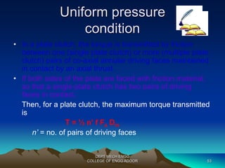
![Uniform pressure
condition
• Again, the equation of torque can be
written as,
T = ½ f Fa Dm
Dm = mean diameter
3 - Di
3)/ (Do
DEPT MECH ENGG
= 2/3 [(Do
2 – Di
2)]
COLLEGE OF ENGG ADOOR 52](https://image.slidesharecdn.com/machinedesignii-141018021819-conversion-gate02/85/Machine-design-52-320.jpg)


![Selection of Roller Chain
• Determine the chain pitch using the equation,
DEPT MECH ENGG
COLLEGE OF ENGG ADOOR 188
pitch ‘
p’ in mm < 10[60.67/n1]2/3
n1 = speed of smaller sprocket in rps
• Select the chain type for the selected pitch
• Select the number of teeth on the smaller sprocket for the given
transmission ratio. Determine the corresponding number of teeth on
the larger sprocket, and the chain velocity.
• For ordinary applications the economical chain speed is 10 to 15
m/s.](https://image.slidesharecdn.com/machinedesignii-141018021819-conversion-gate02/85/Machine-design-188-320.jpg)


![BUCKINGHAM’S EQUATION
FOR DYNAMIC LOAD
The maximum instantaneous load on the tooth, known as
dynamic load is given by Buckingham as follows:
Dynamic load (Fd) =Tangential tooth load (Ft) +
Increment load due to dynamic action (Fi)
Fi = 20.67 v (C b+ Ft) / [20.67 v+( C b+ Ft)1/2]
Where C is called dynamic factor depending upon
the machining errors.
DEPT MECH ENGG
COLLEGE OF ENGG ADOOR 284](https://image.slidesharecdn.com/machinedesignii-141018021819-conversion-gate02/85/Machine-design-284-320.jpg)


The document discusses different types of clutches used in vehicles, including their purpose and design. It describes jaw clutches, friction clutches, and their components like the flywheel, pressure plate, clutch plate, and release bearing. It also covers the operation of single and multi-plate clutches, their materials, and methods for analyzing clutch performance parameters like transmitted torque and temperature rise.