The document discusses the central processing unit and its components. It describes the general register organization and stack organization of a CPU. It discusses the instruction formats used in CPUs, including three address, two address, one address, zero address, and RISC instruction formats. It also covers addressing modes and data transfer and manipulation instructions used in CPUs.

![OPERATION OF CONTROL UNIT
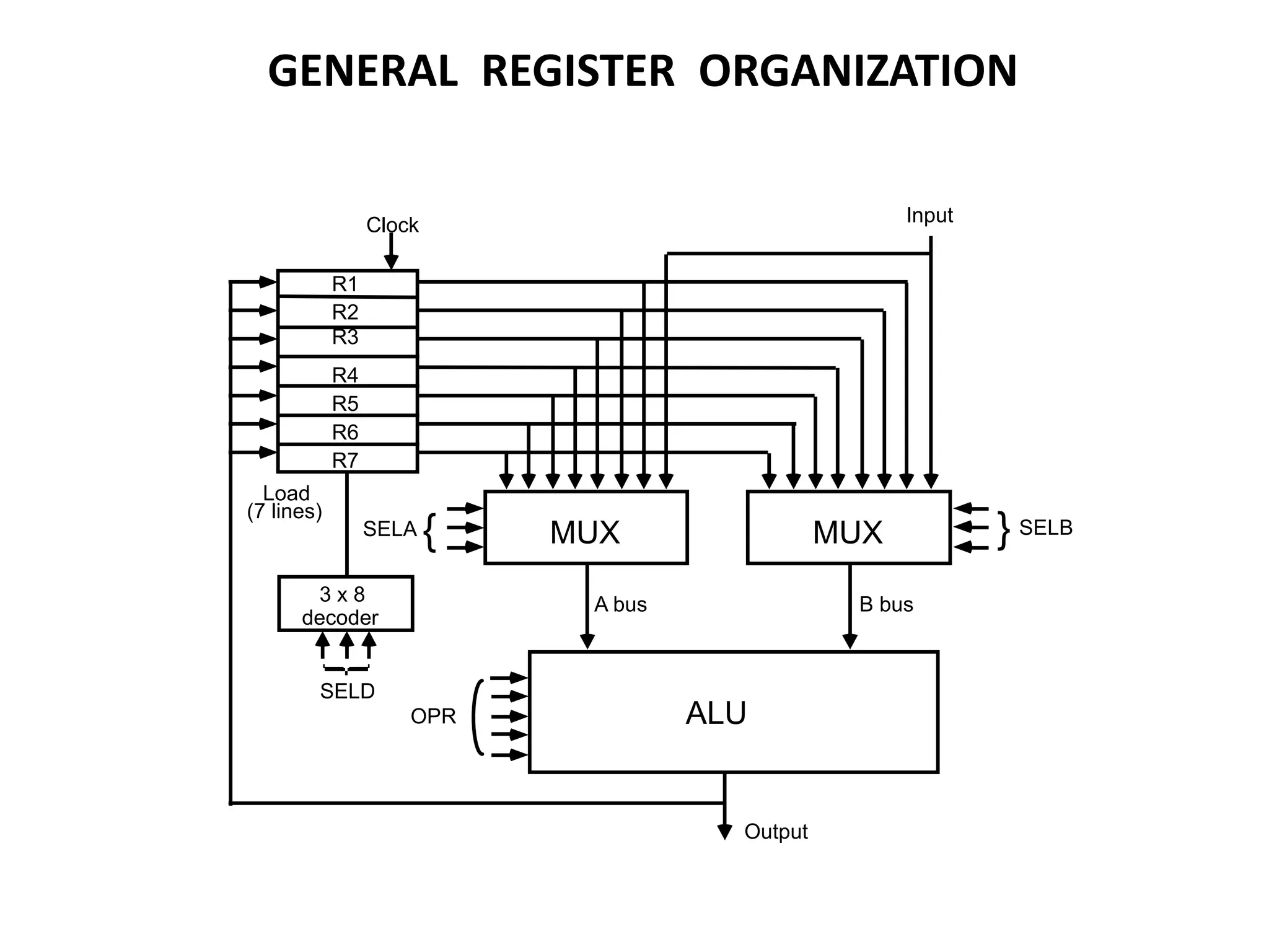
The control unit
Directs the information flow through ALU by
- Selecting various Components in the system
- Selecting the Function of ALU
Example: R1 R2 + R3
[1] MUX A selector (SELA): BUS A R2
[2] MUX B selector (SELB): BUS B R3
[3] ALU operation selector (OPR): ALU to ADD
[4] Decoder destination selector (SELD): R1 Out Bus
Control Word SELA SELB SELD OPR
3 3 3 5
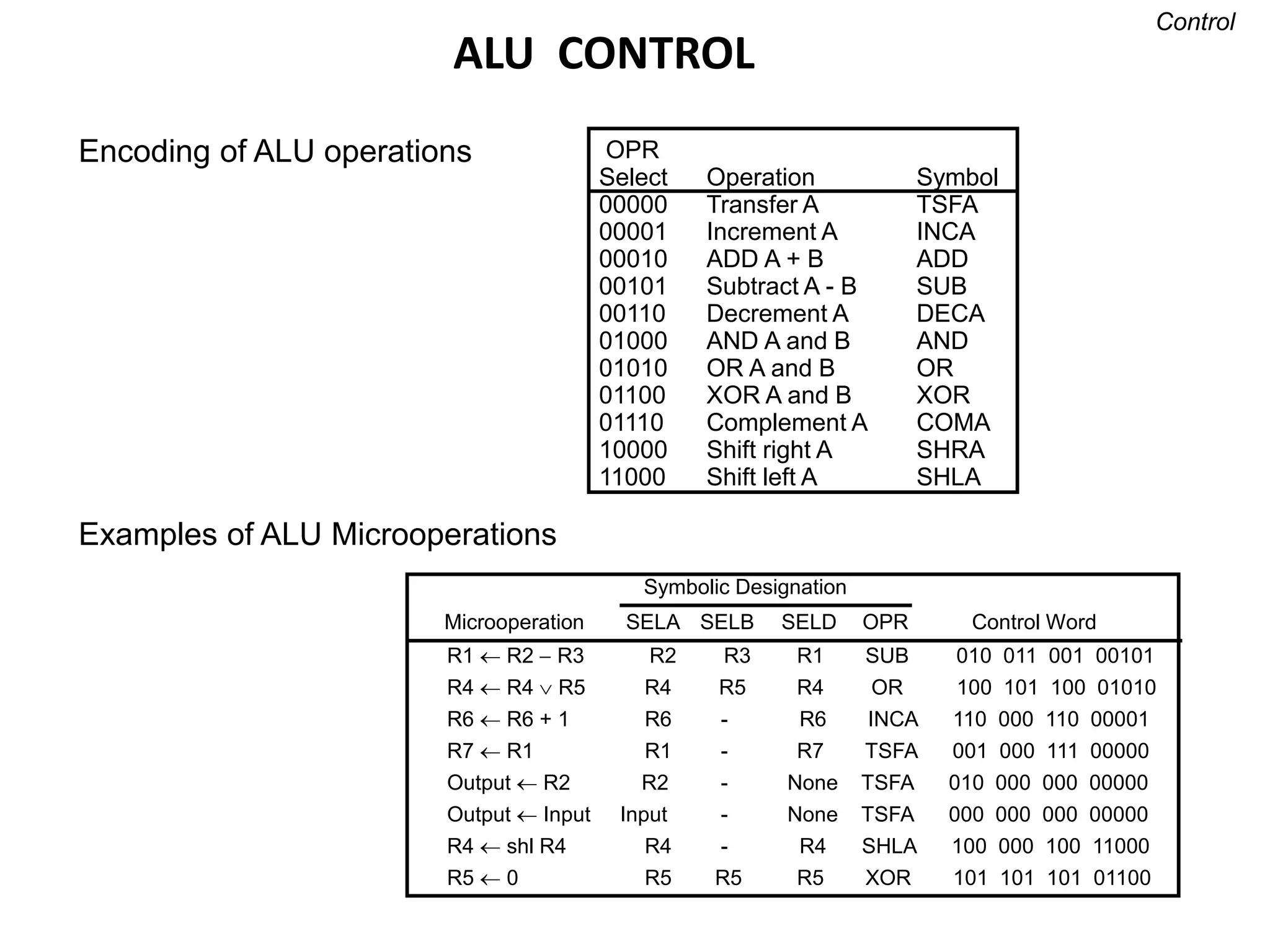
Encoding of register selection fields
Binary
Code SELA SELB SELD
000 Input Input None
001 R1 R1 R1
010 R2 R2 R2
011 R3 R3 R3
100 R4 R4 R4
101 R5 R5 R5
110 R6 R6 R6
111 R7 R7 R7](https://image.slidesharecdn.com/unit-3-230122095845-0941baad/75/UNIT-3-pptx-5-2048.jpg)

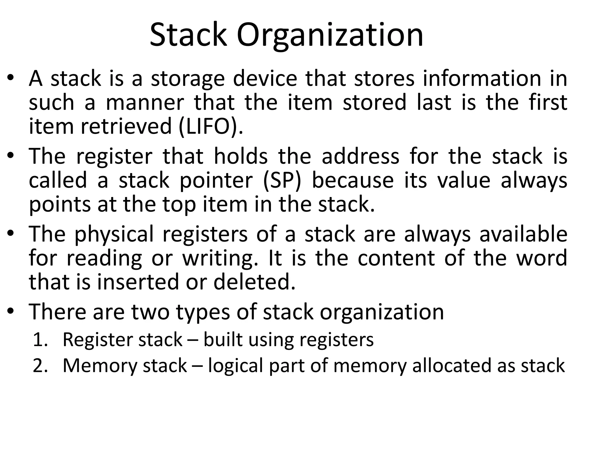
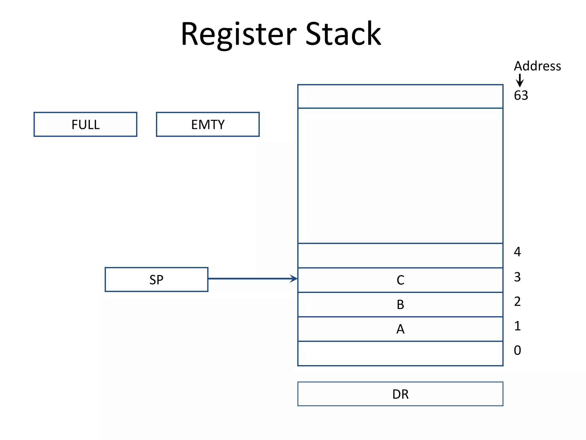
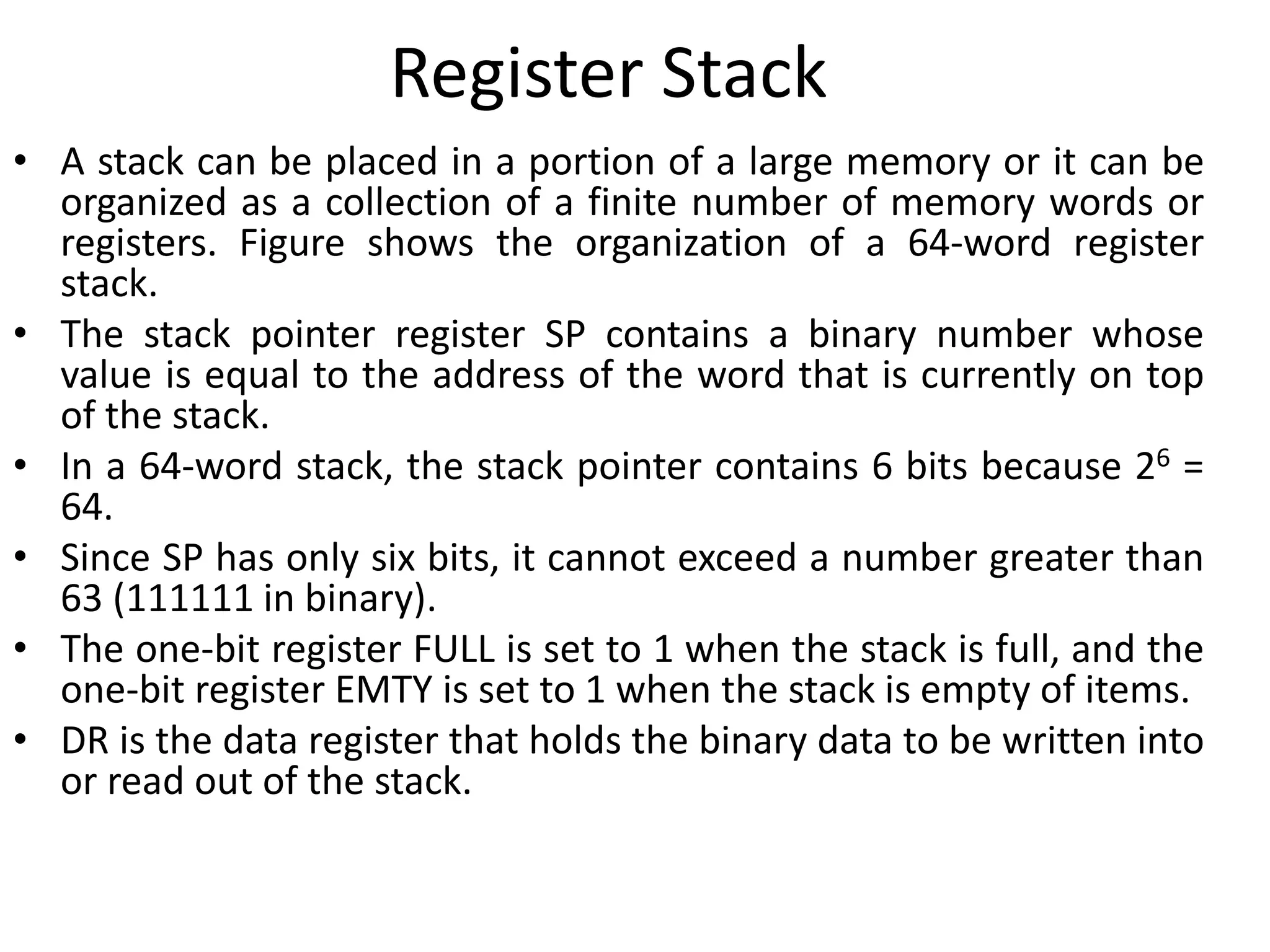
![Register Stack
• PUSH Operation
SP ← SP + 1
M[SP] ← DR
IF (SP= 0) then (FULL ← 1)
EMTY ← 0
POP Operation
DR ← M[SP]
SP ← SP - 1
IF (SP= 0) then (EMTY ← 1)
FULL ← 0
//Increment stack pointer
//Write item on top of the stack
//Check if stack is full
//Mark the stack not empty](https://image.slidesharecdn.com/unit-3-230122095845-0941baad/75/UNIT-3-pptx-11-2048.jpg)
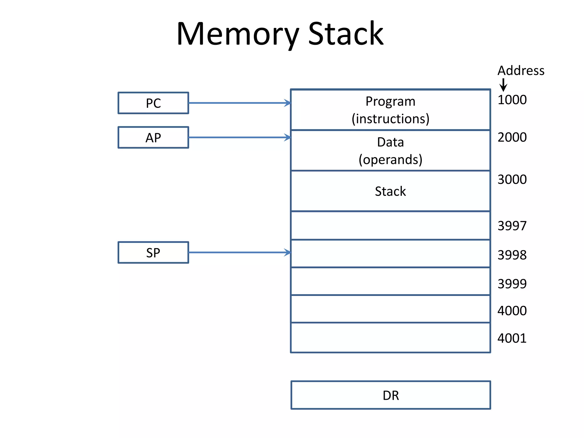
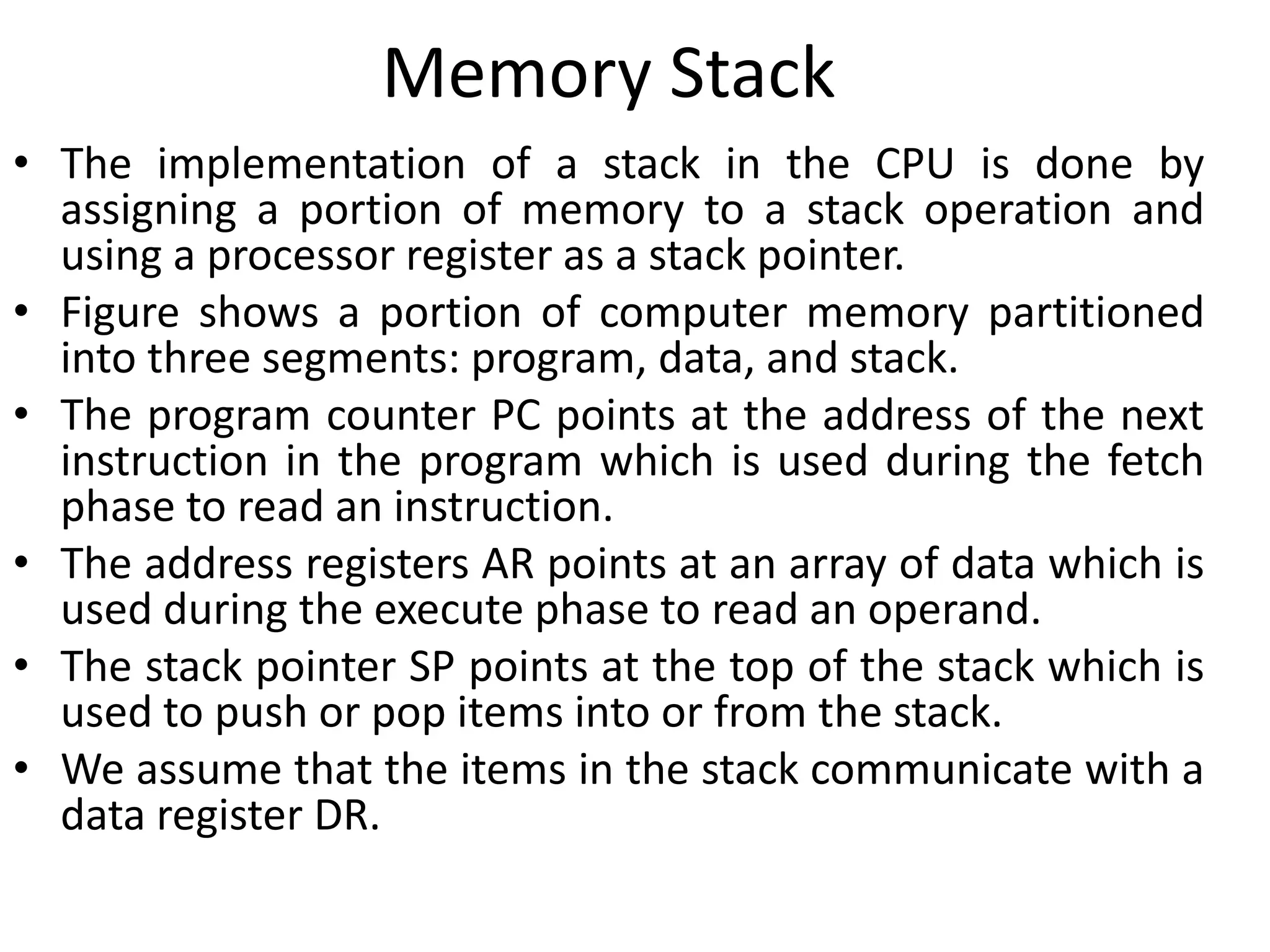
![Memory Stack
• PUSH Operation
SP ← SP - 1
M[SP] ← DR
POP Operation
DR ← M[SP]
SP ← SP + 1](https://image.slidesharecdn.com/unit-3-230122095845-0941baad/75/UNIT-3-pptx-14-2048.jpg)

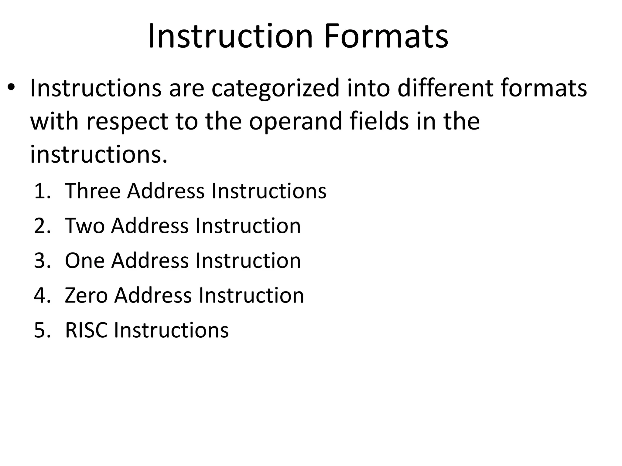
![Three Address Instruction
• Computers with three-address instruction formats can
use each address field to specify either a processor
register or a memory operand.
• The program in assembly language that evaluates X =
(A + B) * (C + D) is shown below.
• The advantage of three-address format is that it results
in short programs when evaluating arithmetic
expressions.
• The disadvantage is that the binary-coded instructions
require too many bits to specify three addresses.
ADD R1, A, B R1← M[A]+ M[B]
ADD R2, C, D R2← M[C]+ M[D]
MUL X, R1, R2 M[X]← R1 * R2](https://image.slidesharecdn.com/unit-3-230122095845-0941baad/75/UNIT-3-pptx-19-2048.jpg)
![Two Address Instruction
• Two address instructions are the most common in
commercial computers. Here again each address field can
specify either a processor register or a memory word.
• The program to evaluate X = (A + B) * (C + D) is as follows:
MOV R1, A R1← M[A]
ADD R1, B R1← R1+ M[B]
MOV R2, C R2← M[C]
ADD R2, D R2← R2+ M[D]
MUL R1, R2 R1← R1 * R2
M[X]← R1
MOV X, R1](https://image.slidesharecdn.com/unit-3-230122095845-0941baad/75/UNIT-3-pptx-20-2048.jpg)
![One Address Instruction
• One address instructions use an implied accumulator (AC)
register for all data manipulation.
• For multiplication and division these is a need for a second
register.
• However, here we will neglect the second register and
assume that the AC contains the result of all operations.
• The program to evaluate X = (A + B) * (C + D) is
LOAD A AC← M[A]
ADD B AC← AC+M[B]
STORE T M[T]←AC
LOAD C AC← M[C]
ADD D AC← AC+M[D]
MUL T AC← AC*M[T]
STORE X M[X]←AC](https://image.slidesharecdn.com/unit-3-230122095845-0941baad/75/UNIT-3-pptx-21-2048.jpg)
![Zero Address Instruction
• A stack-organized computer does not use an address field for the
instructions ADD and MUL.
• The PUSH and POP instructions, however, need an address field to
specify the operand that communicates with the stack.
• The program to evaluate X = (A + B) * (C + D) will be written for a stack-
organized computer.
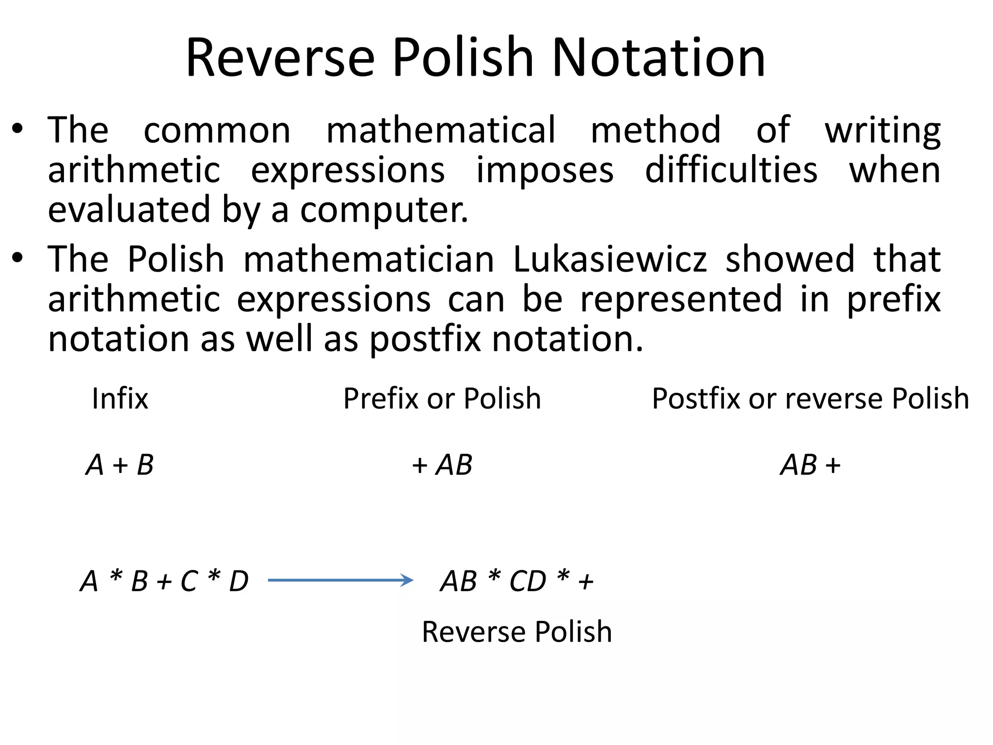
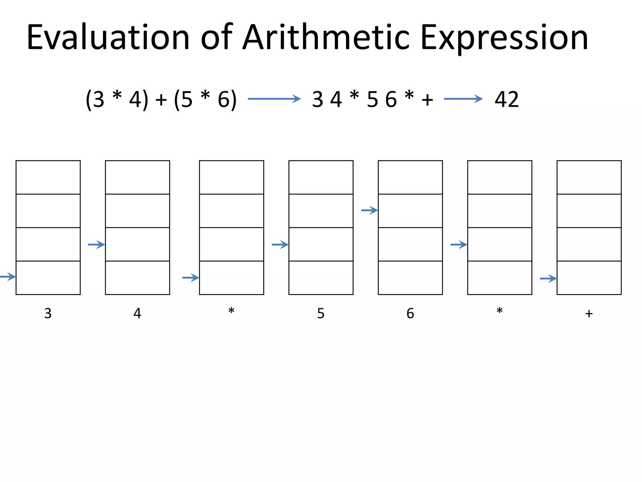
• To evaluate arithmetic expressions in a stack computer, it is necessary to
convert the expression into reverse polish notation.
PUSH A TOS← M[A]
PUSH B TOS← M[B]
ADD TOS←(A+B)
PUSH C TOS← M[C]
PUSH D TOS← M[D]
ADD TOS←(C+D)
MUL TOS←(C+D)*(A+B)
POP X M[X] ← TOS](https://image.slidesharecdn.com/unit-3-230122095845-0941baad/75/UNIT-3-pptx-22-2048.jpg)
![RISC Instruction
• The instruction set of a typical RISC processor is restricted to the use of load
and store instructions when communicating between memory and CPU.
• All other instructions are executed within the registers of the CPU without
referring to memory.
• A program for a RISC type CPU consists of LOAD and STORE instructions that
have one memory and one register address, and computational-type
instructions that have three addresses with all three specifying processor
registers.
• The following is a program to evaluate X = (A + B) * (C + D)
LOAD R1, A R1← M[A]
LOAD R2, B R2← M[B]
LOAD R3, C R3← M[C]
LOAD R4, D R4← M[D]
ADD R1, R1, R2 R1← R1+R2
ADD R3, R3, R4 R3← R3+R4
MUL R1, R1, R3 R1← R1*R3
STORE X, R1 M[X] ← R1](https://image.slidesharecdn.com/unit-3-230122095845-0941baad/75/UNIT-3-pptx-23-2048.jpg)

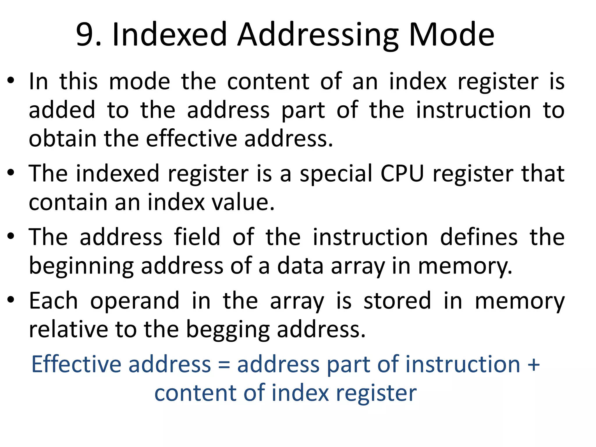
![4. Register Indirect Mode
• In this mode the instruction specifies a register in the CPU
whose contents give the address of the operand in
memory.
• Before using a register indirect mode instruction, the
programmer must ensure that the memory address of the
operand is placed in the processor register with a previous
instruction.
• The advantage of this mode is that address field of the
instruction uses fewer bits to select a register than would
have been required to specify a memory address directly.
• E.g. MOV [R1], R2
value of R2 is moved to the memory location specified in
R1.](https://image.slidesharecdn.com/unit-3-230122095845-0941baad/75/UNIT-3-pptx-30-2048.jpg)