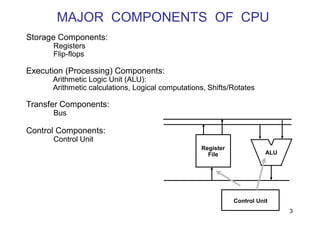
The document discusses the central processing unit (CPU) of a computer system. It describes the major components of the CPU including registers, arithmetic logic unit (ALU), buses, and the control unit. It then explains the general register organization of a CPU and how the control unit directs information flow and selects operations for the ALU. Finally, it discusses various CPU addressing modes, data transfer and manipulation instructions, and different instruction formats used in computer organization.
![OPERATION OF CONTROL UNIT
5
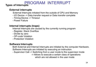
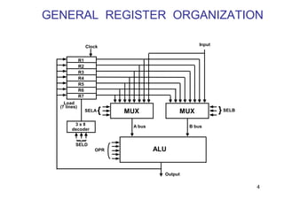
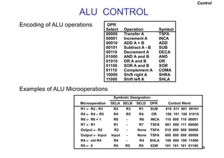
The control unit directs the information flow through ALU by:
- Selecting various Components in the system
- Selecting the Function of ALU
Example: R1 <- R2 + R3
[1] MUX A selector (SELA): BUS A R2
[2] MUX B selector (SELB): BUS B R3
[3] ALU operation selector (OPR): ALU to ADD
[4] Decoder destination selector (SELD): R1 Out Bus
Control Word
Encoding of register selection fields
Binary
Code SELA SELB SELD
000 Input Input None
001 R1 R1 R1
010 R2 R2 R2
011 R3 R3 R3
100 R4 R4 R4
101 R5 R5 R5
110 R6 R6 R6
111 R7 R7 R7
SELA SELB SELD OPR
3 3 3 5](https://image.slidesharecdn.com/7-230405134532-b67c2d0f/85/7-CPU_Unit3-1-pdf-5-320.jpg)
![REGISTER STACK ORGANIZATION
7
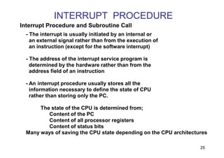
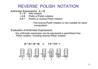
Register Stack
Push, Pop operations
/* Initially, SP = 0, EMPTY = 1, FULL = 0 */
PUSH POP
SP SP + 1 DR M[SP]
M[SP] DR SP SP - 1
If (SP = 0) then (FULL 1) If (SP = 0) then (EMPTY 1)
EMPTY 0 FULL 0
Stack
- Very useful feature for nested subroutines, nested loops control
- Also efficient for arithmetic expression evaluation
- Storage which can be accessed in LIFO
- Pointer: SP
- Only PUSH and POP operations are applicable
A
B
C
0
1
2
3
4
63
Address
FULL EMPTY
SP
DR
Flags
Stack pointer
stack](https://image.slidesharecdn.com/7-230405134532-b67c2d0f/85/7-CPU_Unit3-1-pdf-7-320.jpg)
![MEMORY STACK ORGANIZATION
8
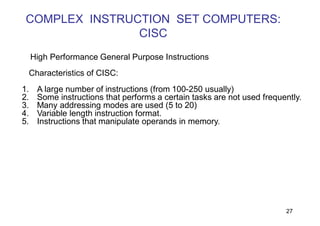
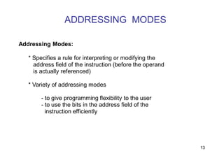
- A portion of memory is used as a stack with a
processor register as a stack pointer
- PUSH: SP SP + 1
M[SP] DR
- POP: DR M[SP]
SP SP - 1
- Most computers do not provide hardware to check
stack overflow (full stack) or underflow(empty stack)
Memory with Program, Data,
and Stack Segments
DR
4001
4000
3999
3998
3997
3000
Data
(operands)
Program
(instructions)
1000
PC
AR
SP
stack](https://image.slidesharecdn.com/7-230405134532-b67c2d0f/85/7-CPU_Unit3-1-pdf-8-320.jpg)
![INSTRUCTION FORMAT
cpe 252: Computer Organization 10
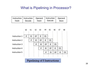
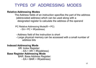
OP-code field - specifies the operation to be performed
Address field - designates memory address(s) or a processor register(s)
Mode field - specifies the way the operand or the
effective address is determined
The number of address fields in the instruction format
depends on the internal organization of CPU
- The three most common CPU organizations:
Instruction Format
Single accumulator organization:
ADD X /* AC AC + M[X] */
General register organization:
ADD R1, R2, R3 /* R1 R2 + R3 */
ADD R1, R2 /* R1 R1 + R2 */
MOV R1, R2 /* R1 R2 */
ADD R1, X /* R1 R1 + M[X] */
Stack organization:
PUSH X /* TOS M[X] */
ADD
Instruction Fields](https://image.slidesharecdn.com/7-230405134532-b67c2d0f/85/7-CPU_Unit3-1-pdf-10-320.jpg)
![THREE, and TWO-ADDRESS INSTRUCTIONS
cpe 252: Computer Organization 11
Three-Address Instructions:
Program to evaluate X = (A + B) * (C + D) :
ADD R1, A, B /* R1 M[A] + M[B] */
ADD R2, C, D /* R2 M[C] + M[D] */
MUL X, R1, R2 /* M[X] R1 * R2 */
- Results in short programs
- Instruction becomes long (many bits)
Two-Address Instructions:
Program to evaluate X = (A + B) * (C + D) :
MOV R1, A /* R1 M[A] */
ADD R1, B /* R1 R1 + M[B] */
MOV R2, C /* R2 M[C] */
ADD R2, D /* R2 R2 + M[D] */
MUL R1, R2 /* R1 R1 * R2 */
MOV X, R1 /* M[X] R1 */](https://image.slidesharecdn.com/7-230405134532-b67c2d0f/85/7-CPU_Unit3-1-pdf-11-320.jpg)
![ONE, and ZERO-ADDRESS INSTRUCTIONS
12
One-Address Instructions:
- Use an implied AC register for all data manipulation
- Program to evaluate X = (A + B) * (C + D) :
LOAD A /* AC M[A] */
ADD B /* AC AC + M[B] */
STORE T /* M[T] AC */
LOAD C /* AC M[C] */
ADD D /* AC AC + M[D] */
MUL T /* AC AC * M[T] */
STORE X /* M[X] AC */
Zero-Address Instructions:
- Can be found in a stack-organized computer
- Program to evaluate X = (A + B) * (C + D) :
PUSH A /* TOS A */
PUSH B /* TOS B */
ADD /* TOS (A + B) */
PUSH C /* TOS C */
PUSH D /* TOS D */
ADD /* TOS (C + D) */
MUL /* TOS (C + D) * (A + B) */
POP X /* M[X] TOS */](https://image.slidesharecdn.com/7-230405134532-b67c2d0f/85/7-CPU_Unit3-1-pdf-12-320.jpg)
![TYPES OF ADDRESSING MODES
14
Implied Mode
Address of the operands are specified implicitly
in the definition of the instruction
- No need to specify address in the instruction
- EA = AC, or EA = Stack[SP], EA: Effective Address.
Immediate Mode
Instead of specifying the address of the operand,
operand itself is specified
- No need to specify address in the instruction
- However, operand itself needs to be specified
- Sometimes, require more bits than the address
- Fast to acquire an operand
Register Mode
Address specified in the instruction is the register address
- Designated operand need to be in a register
- Shorter address than the memory address
- Saving address field in the instruction
- Faster to acquire an operand than the memory addressing
- EA = IR(R) (IR(R): Register field of IR)](https://image.slidesharecdn.com/7-230405134532-b67c2d0f/85/7-CPU_Unit3-1-pdf-14-320.jpg)
![TYPES OF ADDRESSING MODES
15
Register Indirect Mode
Instruction specifies a register which contains
the memory address of the operand
- Saving instruction bits since register address
is shorter than the memory address
- Slower to acquire an operand than both the
register addressing or memory addressing
- EA = [IR(R)] ([x]: Content of x)
Auto-increment or Auto-decrement features:
Same as the Register Indirect, but:
- When the address in the register is used to access memory, the
value in the register is incremented or decremented by 1 (after or
before the execution of the instruction)](https://image.slidesharecdn.com/7-230405134532-b67c2d0f/85/7-CPU_Unit3-1-pdf-15-320.jpg)
![TYPES OF ADDRESSING MODES
16
Direct Address Mode
Instruction specifies the memory address which
can be used directly to the physical memory
- Faster than the other memory addressing modes
- Too many bits are needed to specify the address
for a large physical memory space
- EA = IR(address), (IR(address): address field of IR)
Indirect Addressing Mode
The address field of an instruction specifies the address of a memory
location that contains the address of the operand
- When the abbreviated address is used, large physical memory can
be addressed with a relatively small number of bits
- Slow to acquire an operand because of an additional memory
access
- EA = M[IR(address)]](https://image.slidesharecdn.com/7-230405134532-b67c2d0f/85/7-CPU_Unit3-1-pdf-16-320.jpg)
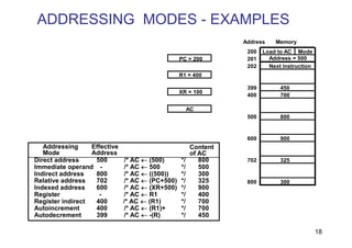
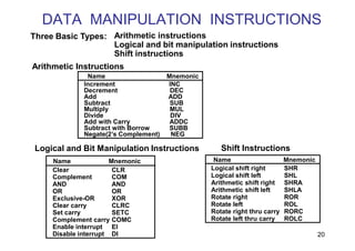
![DATA TRANSFER INSTRUCTIONS
19
Load LD
Store ST
Move MOV
Exchange XCH
Input IN
Output OUT
Push PUSH
Pop POP
Name Mnemonic
Typical Data Transfer Instructions
Direct address LD ADR AC M[ADR]
Indirect address LD @ADR AC M[M[ADR]]
Relative address LD $ADR AC M[PC + ADR]
Immediate operand LD #NBR AC NBR
Index addressing LD ADR(X) AC M[ADR + XR]
Register LD R1 AC R1
Register indirect LD (R1) AC M[R1]
Autoincrement LD (R1)+ AC M[R1], R1 R1 + 1
Autodecrement LD -(R1) R1 R1 - 1, AC M[R1]
Mode
Assembly
Convention Register Transfer
Data Transfer Instructions with Different Addressing Modes](https://image.slidesharecdn.com/7-230405134532-b67c2d0f/85/7-CPU_Unit3-1-pdf-19-320.jpg)
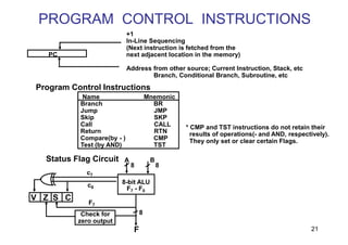
![SUBROUTINE CALL AND RETURN
23
Call subroutine
Jump to subroutine
Branch to subroutine
Branch and save return address
• Fixed Location in the subroutine(Memory)
• Fixed Location in memory
• In a processor Register
• In a memory stack
- most efficient way
SUBROUTINE CALL
Two Most Important Operations are Implied;
* Branch to the beginning of the Subroutine
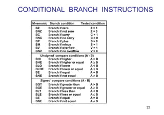
- Same as the Branch or Conditional Branch
* Save the Return Address to get the address
of the location in the Calling Program upon
exit from the Subroutine
- Locations for storing Return Address: CALL
SP SP - 1
M[SP] PC
PC EA
RTN
PC M[SP]
SP SP + 1](https://image.slidesharecdn.com/7-230405134532-b67c2d0f/85/7-CPU_Unit3-1-pdf-23-320.jpg)