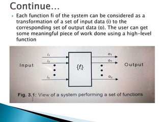
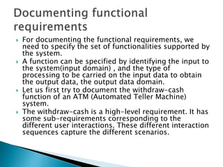
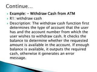
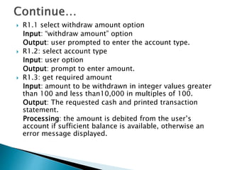
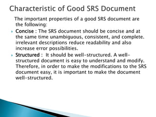
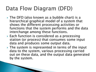
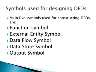
FUNDAMENTALS OF software developement and a detail outcome of the software based on the project management and the various metrics and measurements development in software engineering
fundamentals of software engineering.this unit covers all the aspects of software engineering coding standards and naming them and code inspectionna an d various testing methods and
The document discusses software scope, which involves determining project goals, tasks, costs, and deadlines. It also describes functions, performance, constraints, and interfaces. The first step in software project planning is to determine scope by assessing functions and performance allocated to software. Scope is identified by asking the customer questions about goals, benefits, problems, and environment. An example of determining scope for a conveyor line sorting system is provided.
This document provides an overview of software estimation techniques. It discusses why estimation is important, the general estimation process, and factors that impact accuracy such as requirements management and experience. The document also describes different estimation methods like expert judgment, analogy-based, top-down, and bottom-up. It provides examples of estimation tools like Function Point Analysis and COCOMO II for sizing and effort estimation.
This document provides an overview and introduction to software metrics. It discusses measurement concepts and why measurement is important for software engineering. It covers topics like the basics of measurement, collecting metrics data, analyzing data, and measuring internal and external attributes of software. Specific metrics discussed include size, structure, complexity, reliability, and test coverage. The document is intended to introduce readers to fundamental software metrics concepts.
Here are the key steps to estimate the effort required to develop the stock control system using function point analysis:
1. Identify the 5 functional components - External Inputs, External Outputs, External Inquiries, External Interface Files, Internal Logic Files.
2. Classify each component as Simple, Average or Complex based on the description provided. For example, orders and payments would likely be Complex External Inputs.
3. Assign the appropriate weight (3, 4, 6 etc.) to each component based on its complexity.
4. Multiply each weight by its quantity to get component value.
5. Add up all component values to get the total function points of the system.
6. Use the function
The document discusses various software project size estimation metrics. It describes the limitations of lines of code (LOC) counting, such as variability due to coding style and not accounting for non-coding effort. Function point analysis and feature point analysis are presented as alternatives that overcome some LOC limitations by basing size on software features rather than lines. The key steps of function point analysis involve counting types of inputs, outputs, inquiries and other parameters to calculate unadjusted function points which are then adjusted based on technical complexity factors. While more accurate than LOC, function point analysis is still subjective based on how parameters are defined and counted.
The document provides an overview of different techniques for estimating the size of software projects, including fuzzy logic sizing, standard component sizing, Delphi estimation, function points analysis, and extended metrics like feature points and 3D function points. It discusses estimating project schedule, costs, resources needed, and quality. Historical data, decomposition of tasks, and empirical cost models are recommended to achieve reliable estimates.
1. Software project estimation involves decomposing a project into smaller problems like major functions and activities. Estimates can be based on similar past projects, decomposition techniques, or empirical models.
2. Accurate estimates depend on properly estimating the size of the software product using techniques like lines of code, function points, or standard components. Baseline metrics from past projects are then applied to the size estimates.
3. Decomposition techniques involve estimating the effort needed for each task or function and combining them. Process-based estimation decomposes the software process into tasks while problem-based estimation decomposes the problem.
The document discusses software size estimation and compares two common metrics: lines of code (LOC) and function points (FP). LOC counts lines and has issues like being dependent on programming style and technology. FP measures functionality from the user perspective independently of technology. It can be used earlier for planning while LOC can only be counted after coding. FP is a more standardized and useful metric for estimating resources, time, cost and comparing projects.
The document discusses software engineering and process models. It defines software engineering as the application of systematic and quantifiable approaches to software development, operation and maintenance. It describes software as computer programs, data structures and documentation.
It then discusses characteristics of software such as it being engineered not manufactured, not wearing out over time, and continuing to be custom built in most cases. It also discusses the software engineering layers including the process, method and tools layers.
Finally, it discusses the software process as a framework involving key activities like communication, planning, modeling, construction and deployment. It explains the generic process model and how activities are populated by actions and tasks to produce work products.
This document outlines several principles that should guide software engineering practices according to experts. It discusses principles for processes, modeling, construction, communication, planning, and deployment. Some key principles include being agile, focusing on quality, adapting when needed, building effective teams, managing risk and change, and testing software thoroughly. The document provides over 100 specific principles across different phases of software development.
The document provides an introduction to software engineering and process models. It defines key terms like software, software engineering, and characteristics of software. It then discusses software engineering as a layered technology with process, method, and tools layers. The document also explains the software process as consisting of five generic activities - communication, planning, modeling, construction, and deployment. It provides examples and definitions for each activity. Finally, it asks exam questions related to defining software engineering and explaining it as a layered technology.
This presentation describes:
- What is software size?
- How to Measure Software size?
- Techniques and parameters in Software Size estimation
- Where and how to apply the techniques?
The document provides an overview of software project estimation techniques. It discusses that estimation involves determining the money, effort, resources and time required to build a software system. The key steps are: describing product scope, decomposing problems, estimating sub-problems using historical data and experience, and considering complexity and risks. It also covers decomposition techniques, empirical estimation models like COCOMO II, and factors considered in estimation like resources, feasibility and risks.
This course covers software requirement engineering over 10 topics, including basics, processes, management, and tools. Students will be assessed through a final exam (60%), midterm (15%), and tutorials/presentations (25%). The course lab will provide hands-on experience with requirements tools and models. Requirements are conditions that must be met by a system, and define customer expectations, system boundaries, and quality attributes from different perspectives. Poor requirements can lead to imprecise, ambiguous, contradictory, changing, low quality requirements or missing requirements.
Software Metrics for Identifying Software Size in Software Development ProjectsVishvi Vidanapathirana
This paper defines the best software metrics that can be used to define the size of the software in the current industry of information technology (IT)
The document discusses the process of requirements engineering. It begins by defining requirements engineering as the process of defining, documenting, and maintaining requirements. It then outlines the key tasks in requirements engineering: inception, elicitation, elaboration, negotiation, specification, validation, and management. For each task, it provides details on the goals and steps involved. Overall, the document provides a comprehensive overview of requirements engineering and the various activities that comprise the process.
Decomposition technique In Software Engineering Bilal Hassan
The document discusses different techniques for estimating software project costs and effort, including decomposition, sizing, and function point analysis. It provides an example of estimating the lines of code and function points for a mechanical CAD software project. Estimates are developed by decomposing the problem into smaller elements and tasks, and estimating the effort required for each. The accuracy of estimates depends on properly sizing the software and having reliable past project metrics.
The document discusses software maintenance. It defines software maintenance as modifying software after delivery to correct faults, improve performance, or adapt to environmental changes. Maintenance activities include error correction, enhancing capabilities, deleting obsolete functions, and optimization. Lehman's Law states that software maintenance is evolutionary development and past maintenance informs future decisions. The challenges of software maintenance include technical issues like testing and limited understanding, as well as management issues like cost estimation and priorities.
The document discusses software engineering requirements analysis and specification. It covers topics like software requirements types (functional and non-functional), requirement engineering process, feasibility studies, requirements elicitation and analysis. The requirement engineering process involves activities like requirements discovery, analysis, specification, validation and management. It also discusses preparing a software requirements document that defines system specifications.
Introduction to Software Cost EstimationHemanth Raj
This document provides an introduction to software cost estimation. It discusses how software cost estimation has evolved from simple programs with few parameters to complex modern applications that require estimating numerous parameters. Key parameters that influence cost estimates include project size, requirements volatility, team capabilities, and development tools and methodologies to be used. The document also describes how commercial software cost estimation tools work, including using templates based on attributes of similar past projects to generate estimates. Finally, it outlines the typical 10-step sequence used to generate software cost estimates.
This document discusses software metrics for processes, projects, and products. It defines metrics as quantitative measures used as management tools to provide insight. Metrics in the process domain are used for strategic decisions, while project metrics enable tactical decisions. Size-oriented metrics normalize measures by lines of code or function points. Function-oriented metrics use functionality as a normalization value. Quality metrics measure correctness and maintainability. Establishing a metrics baseline from past projects allows for process, product, and project improvements.
Software metricsIntroduction
Attributes of Software Metrics
Activities of a Measurement Process
Types
Normalization of Metrics
Help software engineers to gain insight into the design and construction of the software
Activities of a Measurement Process
To answer this we need to know the size & complexity of the projects.
But if we normalize the measures, it is possible to compare the two
For normalization we have 2 ways-
Size-Oriented Metrics
Function Oriented Metrics
Defect effort prediction models in software maintenance projectsiaemedu
The document discusses models for predicting defects in software maintenance projects. It describes how data on defects found during testing is recorded and used by reliability models to predict remaining defects. The paper proposes exploring defect data through appropriate statistics and predictive models like decision trees and Naive Bayes classifiers. It outlines steps for analyzing defect data with statistics to gain insights, including using ratios of defects found before and after release to assess quality. Graphs are suggested to examine the impact of previous releases on current release quality.
The document discusses software quality assurance plans and methods. It defines quality, describes quality control and assurance activities like inspections, reviews and testing. It explains factors that affect quality like correctness, reliability, maintainability. Methods to assure quality discussed are verification and validation, inspections, reviews, and static analysis. The document also covers project monitoring plans and tools, software design fundamentals, objectives of design, design principles and strategies.
The document provides an overview of requirements analysis and specification. It discusses the importance of thoroughly understanding requirements before building a system. Requirements analysis involves gathering requirements through techniques like interviews and analyzing them to resolve inconsistencies. The key outputs are the software requirements specification document, which describes the system functions, non-functional requirements, and constraints in a black-box manner. Complex logic is represented using decision trees and tables. The overall goals are to fully understand user needs and document them properly to form the basis for development.
The document provides an overview of requirements engineering for software development. It discusses the importance of requirements specification, different types of requirements (functional, non-functional), and techniques for modeling requirements such as data flow diagrams, entity relationship diagrams, and structured English.
The document discusses the process of analyzing client requirements for a new system. This includes gathering information from clients, clarifying needs, structuring requirements, and confirming with clients that all functional, quality, and other needs have been identified correctly and fall within the project scope. The key steps are analyzing the information gathered, documenting the requirements, and obtaining final sign-off from stakeholders to finalize the requirements document.
This document discusses requirements engineering for software projects. It begins by defining what requirements are, noting that they can range from abstract statements to detailed specifications. There are three types of requirements documents: requirements definition for customers, requirements specification for contracts, and software specifications for developers. The document outlines the sources of requirements, key tasks in requirements engineering like elicitation and validation, and challenges in getting requirements right. It also discusses techniques for gathering requirements like inception, collaborative meetings, use cases, and elaboration of requirements into an analysis model.
The document introduces concepts related to requirements engineering for a software project. It discusses user and system requirements, including functional and non-functional requirements. As an example, it analyzes requirements for an Indian railway reservation system, identifying different user types and their expectations of the system. It also discusses documenting, eliciting, analyzing and classifying requirements.
This document discusses the requirements workflow in software development. It describes capturing and managing requirements to design a user-focused system. The goals are to establish agreement on what the system should do, provide understanding of requirements to developers, define system boundaries, and provide a basis for planning, estimating, and defining the user interface. Requirements include functional requirements specifying system actions and non-functional requirements related to qualities like usability, reliability, performance, and supportability. Requirements come from stakeholders' requests and needs and are expressed as system features.
SE_Lec 03_Requirements Analysis and SpecificationAmr E. Mohamed
The document discusses requirements engineering and defines what requirements are. It explains that requirements include functional and non-functional requirements. Functional requirements define what a system should do, while non-functional requirements define properties like usability, performance and reliability. The document also describes the requirements engineering process, which involves gathering, analyzing, documenting and managing requirements.
The document discusses identifying requirements from problem statements. It begins by explaining the importance of requirements identification as the first step of any software development project. It then discusses objectives like identifying ambiguities, inconsistencies, and incompleteness in requirements. The document categorizes requirements as functional and non-functional. It provides examples of each and discusses identifying them from problem statements. It also discusses preparing a Software Requirements Specification once requirements are identified.
The document summarizes key aspects of system engineering and requirements engineering processes. It discusses how system engineering occurs as a consequence of defining computer-based systems and their elements. It also explains the different levels of abstraction in requirements engineering from inception to specification and management. Example techniques for eliciting requirements like use cases and collaborative meetings are also outlined.
SE2023 0201 Software Analysis and Design.pptxBharat Chawda
This document provides an overview of software analysis and design. It discusses requirements gathering and analysis, the software requirements specification document, the design process, concepts of cohesion and coupling, data modeling, data flow diagrams, scenario based modeling, and architectural design decisions. The document is intended as a curriculum for diploma students in computer/IT engineering based on textbooks on software engineering. It covers topics such as the system analyst role, requirements elicitation techniques, requirements analysis to identify anomalies, characteristics of a good requirements specification, classification of customer requirements, the design process, design methodologies, and classifications of cohesion and coupling.
The document discusses different types of requirements for software systems including:
- User requirements written from the user's perspective
- System requirements that expand on user requirements for system design
- Software design specification requirements that provide an implementation-oriented description for developers
- Functional requirements that describe system services/functions, and non-functional requirements (NFRs) that define overall system qualities
Some examples of NFRs discussed are performance, reliability, usability, efficiency, maintainability, portability, scalability, and security. The document also describes problems with natural language requirements and different classifications of NFRs.
This document will guide you about the procedures that Konstant follow in the Requirement Gathering Phase once the project is awarded to Konstant. As Konstant understands that requirement gathering is a vital part of successful project management and application development. We don’t want to blame the customers for not being sufficiently clear about their business requirements. Sometime clients/users are guided through a process that elicits their business requirements and facilitates accurate application development, but our analysts are well versed in both understanding the concepts of business requirement gathering AND the process that will best document them.
INTRODUCTION to software engineering requirements specificationskylan2
The document discusses software requirements and their importance. It defines requirements as specifications of what a system should implement. Requirements include functional requirements that describe system services and non-functional requirements that constrain the system or development process. User requirements are high-level descriptions written for users, while system requirements provide more detailed specifications. An effective software requirements specification establishes agreements between customers and developers, reduces defects, and provides a baseline for project planning, validation, and future enhancements.
The document summarizes key concepts from a lecture on requirement engineering. It defines requirements as descriptions of the services and constraints needed for a system. Requirement engineering is the process of discovering, analyzing, documenting, and validating system requirements through tasks like stakeholder interviews, document analysis, and specification. It explains that requirements come from users and stakeholders, and are documented in various forms like user requirements, system requirements, and software design specifications to communicate needs to different audiences like clients, engineers, and developers.
The document discusses requirements definition and system modeling. It defines requirements as conditions or capabilities needed by stakeholders to solve problems or achieve objectives. Requirements should be defined at three levels - business, user, and product. Business requirements define problems to be solved or opportunities addressed. User requirements describe functionality from the user perspective. Product requirements specify functionality that must be built into the software. System modeling helps understand functionality and communicate with customers using models from different perspectives. Requirements definition and system modeling lay the foundation for software development.
The document discusses different types of requirements for software systems. It defines requirements as statements that describe what a system must do. There are two main types: functional requirements, which define the behaviors and functions of the system, and non-functional requirements, which define qualities like performance, reliability, and security. Requirements must be clear, unambiguous statements to avoid issues during system development. Domain requirements also exist that are specific to the application area of the system.
The document discusses software requirements engineering and provides definitions and examples of different types of software requirements. It defines requirements as specifications of what should be implemented and describes requirements at different levels - business requirements, user requirements, functional requirements, system requirements, and non-functional requirements. The document also discusses the importance of requirements, sources of requirements, and examples of software requirements.
The document discusses requirements analysis and specification, which involves gathering requirements, analyzing them to understand user needs and resolve inconsistencies, and documenting the requirements in a Software Requirements Specification (SRS) document. The goals are to fully understand what the customer wants and remove any issues from the requirements. A systems analyst performs requirements analysis by collecting data, analyzing it to understand what needs to be done, and writing the SRS. The SRS serves as a contract between the development team and customer that defines functional and non-functional requirements as well as constraints.
Software Development Process - REQUIREMENTS ANALYSIS / ANALYSIS OF TECHNICAL...Mark John Lado, MIT
The document discusses requirements analysis, which is the first stage of the software development process. It involves eliciting requirements from stakeholders, analyzing the requirements for clarity and consistency, and documenting them. Common techniques for requirements analysis include stakeholder interviews, prototypes, use cases, and software requirements specifications. The goals are to determine what functionality and constraints the system needs to meet business needs.
fundamentals of software engineering a deep study of diagrams DFD ER use case Activity and many others functional and non functional requirements listed required by customer
Working with user accounts,modification,deletion and creating a group its policies and share and printer sharing over a network and windows server backup 2008
The document discusses various directory services and remote access technologies. It begins by defining directory services and their key characteristics like hierarchical naming, extended search capabilities, and distributed information models. It then describes several specific directory services - Novell Directory Service (NDS), Windows Domains, X.500, and LDAP. It also discusses Active Directory architecture and concepts like objects, containers, and naming conventions. The document concludes by covering several remote access technologies like PSTN, ISDN, DSL, and VPNs.
This document discusses the topic of matter and its various states and properties. It defines matter as anything that takes up space and has mass. There are three main states of matter: solids, liquids, and gases. Matter can change between these states through physical processes like melting, freezing, boiling, and condensing. Properties, both intensive and extensive, are used to identify and describe different types of matter and substances. The document also discusses mixtures, elements, compounds, solutions, and alloys.
We have compiled the most important slides from each speaker's presentation. This year’s compilation, available for free, captures the key insights and contributions shared during the DfMAy 2024 conference.
DEEP LEARNING FOR SMART GRID INTRUSION DETECTION: A HYBRID CNN-LSTM-BASED MODELgerogepatton
As digital technology becomes more deeply embedded in power systems, protecting the communication
networks of Smart Grids (SG) has emerged as a critical concern. Distributed Network Protocol 3 (DNP3)
represents a multi-tiered application layer protocol extensively utilized in Supervisory Control and Data
Acquisition (SCADA)-based smart grids to facilitate real-time data gathering and control functionalities.
Robust Intrusion Detection Systems (IDS) are necessary for early threat detection and mitigation because
of the interconnection of these networks, which makes them vulnerable to a variety of cyberattacks. To
solve this issue, this paper develops a hybrid Deep Learning (DL) model specifically designed for intrusion
detection in smart grids. The proposed approach is a combination of the Convolutional Neural Network
(CNN) and the Long-Short-Term Memory algorithms (LSTM). We employed a recent intrusion detection
dataset (DNP3), which focuses on unauthorized commands and Denial of Service (DoS) cyberattacks, to
train and test our model. The results of our experiments show that our CNN-LSTM method is much better
at finding smart grid intrusions than other deep learning algorithms used for classification. In addition,
our proposed approach improves accuracy, precision, recall, and F1 score, achieving a high detection
accuracy rate of 99.50%.
Harnessing WebAssembly for Real-time Stateless Streaming PipelinesChristina Lin
Traditionally, dealing with real-time data pipelines has involved significant overhead, even for straightforward tasks like data transformation or masking. However, in this talk, we’ll venture into the dynamic realm of WebAssembly (WASM) and discover how it can revolutionize the creation of stateless streaming pipelines within a Kafka (Redpanda) broker. These pipelines are adept at managing low-latency, high-data-volume scenarios.
ACEP Magazine edition 4th launched on 05.06.2024Rahul
This document provides information about the third edition of the magazine "Sthapatya" published by the Association of Civil Engineers (Practicing) Aurangabad. It includes messages from current and past presidents of ACEP, memories and photos from past ACEP events, information on life time achievement awards given by ACEP, and a technical article on concrete maintenance, repairs and strengthening. The document highlights activities of ACEP and provides a technical educational article for members.
Adaptive synchronous sliding control for a robot manipulator based on neural ...IJECEIAES
Robot manipulators have become important equipment in production lines, medical fields, and transportation. Improving the quality of trajectory tracking for
robot hands is always an attractive topic in the research community. This is a
challenging problem because robot manipulators are complex nonlinear systems
and are often subject to fluctuations in loads and external disturbances. This
article proposes an adaptive synchronous sliding control scheme to improve trajectory tracking performance for a robot manipulator. The proposed controller
ensures that the positions of the joints track the desired trajectory, synchronize
the errors, and significantly reduces chattering. First, the synchronous tracking
errors and synchronous sliding surfaces are presented. Second, the synchronous
tracking error dynamics are determined. Third, a robust adaptive control law is
designed,the unknown components of the model are estimated online by the neural network, and the parameters of the switching elements are selected by fuzzy
logic. The built algorithm ensures that the tracking and approximation errors
are ultimately uniformly bounded (UUB). Finally, the effectiveness of the constructed algorithm is demonstrated through simulation and experimental results.
Simulation and experimental results show that the proposed controller is effective with small synchronous tracking errors, and the chattering phenomenon is
significantly reduced.
Advanced control scheme of doubly fed induction generator for wind turbine us...IJECEIAES
This paper describes a speed control device for generating electrical energy on an electricity network based on the doubly fed induction generator (DFIG) used for wind power conversion systems. At first, a double-fed induction generator model was constructed. A control law is formulated to govern the flow of energy between the stator of a DFIG and the energy network using three types of controllers: proportional integral (PI), sliding mode controller (SMC) and second order sliding mode controller (SOSMC). Their different results in terms of power reference tracking, reaction to unexpected speed fluctuations, sensitivity to perturbations, and resilience against machine parameter alterations are compared. MATLAB/Simulink was used to conduct the simulations for the preceding study. Multiple simulations have shown very satisfying results, and the investigations demonstrate the efficacy and power-enhancing capabilities of the suggested control system.
HEAP SORT ILLUSTRATED WITH HEAPIFY, BUILD HEAP FOR DYNAMIC ARRAYS.
Heap sort is a comparison-based sorting technique based on Binary Heap data structure. It is similar to the selection sort where we first find the minimum element and place the minimum element at the beginning. Repeat the same process for the remaining elements.
Understanding Inductive Bias in Machine LearningSUTEJAS
This presentation explores the concept of inductive bias in machine learning. It explains how algorithms come with built-in assumptions and preferences that guide the learning process. You'll learn about the different types of inductive bias and how they can impact the performance and generalizability of machine learning models.
The presentation also covers the positive and negative aspects of inductive bias, along with strategies for mitigating potential drawbacks. We'll explore examples of how bias manifests in algorithms like neural networks and decision trees.
By understanding inductive bias, you can gain valuable insights into how machine learning models work and make informed decisions when building and deploying them.
6th International Conference on Machine Learning & Applications (CMLA 2024)ClaraZara1
6th International Conference on Machine Learning & Applications (CMLA 2024) will provide an excellent international forum for sharing knowledge and results in theory, methodology and applications of on Machine Learning & Applications.
Using recycled concrete aggregates (RCA) for pavements is crucial to achieving sustainability. Implementing RCA for new pavement can minimize carbon footprint, conserve natural resources, reduce harmful emissions, and lower life cycle costs. Compared to natural aggregate (NA), RCA pavement has fewer comprehensive studies and sustainability assessments.
A review on techniques and modelling methodologies used for checking electrom...nooriasukmaningtyas
The proper function of the integrated circuit (IC) in an inhibiting electromagnetic environment has always been a serious concern throughout the decades of revolution in the world of electronics, from disjunct devices to today’s integrated circuit technology, where billions of transistors are combined on a single chip. The automotive industry and smart vehicles in particular, are confronting design issues such as being prone to electromagnetic interference (EMI). Electronic control devices calculate incorrect outputs because of EMI and sensors give misleading values which can prove fatal in case of automotives. In this paper, the authors have non exhaustively tried to review research work concerned with the investigation of EMI in ICs and prediction of this EMI using various modelling methodologies and measurement setups.
2. Identify software requirement
Analyze and design requirement
Develop Activity and use-case diagram
Topics and Sub-topics
Requirement Gathering and Analysis
Software Requirement Specification(SRS)
Characteristic ,Customer requirement ,Functional Requirement
Design Process
Classification of Design Activities and Design Methodology
Cohesion and Coupling
Data Modelling Concepts
Data Objects ,Data Attributes ,Relationships ,Cardinality and Modality
Data-Flow Diagrams
Primitive Symbols of DFD ,Develop DFD Model of System Shortcoming of
DFD Model
Scenario-Based Modelling
Writing Use-Cases and Developing an Activity Diagram
Architectural design decisions
Architectural views , Architectural patterns ,Application architectures
3. The requirements analysis and specification
phase starts once the feasibility study phase
is complete and the project is found to be
financially and technically feasible.
Goal of this phase is to clearly understand the
customer requirements and to systematically
organize these requirements in a
specification document.
This phase consist of the two activities:
o Requirements gathering and analysis
o Requirements specification
4. Requirements Gathering : it involves interviewing
the end users and customers and studying the
existing documents to collect all possible
information of the system.
If there is no old working system is present than
this task is required more imagination and
creativity.
Analysis of gathered requirements : the main
purpose of this activity is to clearly understand the
exact requirements of the customer
The following basic questions can be used to
understand exact requirement.
5. What is the problem?
Why is it important to solve the problem?
What are the possible solutions to the problem?
What exactly are the data input to the system and
what exactly are the data output by the system?
What are the likely complexities that might arise
while solving the problem?
If there are external software or hardware with
which the developed software has to interface,
then what exactly would the data interchange
formats with the external system be?
6. After the analyst has understood the exact
customer requirements, he proceeds to identify
and resolve the various requirements problems.
The most important requirements problems that
the analyst has to identify and eliminate are the
problems of anomalies, inconsistencies, and
incompleteness.
When the analyst detects any inconsistencies,
anomalies or incompleteness in the gathered
requirements, he resolves them by carrying out
further discussions with the end users
and the customers.
7. After the software analyst has collect all
information and remove all problems than he starts
to systematically organize the requirements in the
form of SRS document.
SRS Document usually contains all the user
Requirements. it is a contract document between
customer and development organization.
Once the customer agree to SRS Document the
development team starts to develop the product
and implement all functionalities which are
specified in SRS document.
There are many types of users of SRS Document
during software development process.
8. Users ,Customers and marketing personnel.
Software developers.
Test Engineers.
User Documentation writers.
Project managers.
Maintaince engineers
9. The important parts of SRS document are:
Functional requirements of the system
Non-functional requirements of the system
Goals of implementation
Functional requirements:-
The functional requirements part discusses the
functionalities required from the system.
The system is considered to perform a set of high-
level functions {fi}.
10. Each function fi of the system can be considered as a
transformation of a set of input data (i) to the
corresponding set of output data (o). The user can get
some meaningful piece of work done using a high-level
function
11. Nonfunctional requirements deal with the
characteristics of the system which can not be
expressed as functions - such as the
maintainability of the system, portability of the
system, usability of the system, etc.
Nonfunctional requirements may include:
reliability issues,
accuracy of results,
human - computer interface issues,
constraints on the system implementation, etc.
12. The goals of implementation part documents some
general suggestions regarding development.
The goals of implementation section might
document issues such as revisions to the system
functionalities that may be required in the future,
new devices to be supported in the future,
reusability issues, etc.
These are the items which the developers might
keep in their mind during development so that the
developed system may meet some aspects that are
not required immediately.
13. So if the requirements in form of the function
(input and output) than you can documented
as a functional requirements.
Any other requirements which can be verified
by inspecting the system, are documented as
a non-functional requirements.
The suggestions for the developers , are
documented as goals of the implementation.
14. The high-level functional requirements often
need to be identified either from problem
description or from a conceptual
understanding of the problem.
Each high-level requirement means to
perform some meaningful piece of work.
There can be many types of users of a system
and their requirements from the system may
be very different. So, it is often useful to
identify the different types of users who
might use the system and then try to identify
the requirements from each user.
15. Here we list all functions {fi} that the system
performs. Each function fi as shown in fig.is
considered as a transformation of a set of input
data to some corresponding output data.
16. Example: Consider the case of the library system, where
F1: Search Book function
Input: an author’s name
Output: details of the author’s books and the location
of these books in the library
17. So the function Search Book (F1) takes the
author's name and transforms it into book
details.
Functional requirements actually describe a
set of high-level requirements, where each
high-level requirement takes some data from
the user and provides some data to the user
as an output.
Also each high-level requirement might
consist of someother functions.
18. For documenting the functional requirements, we
need to specify the set of functionalities supported by
the system.
A function can be specified by identifying the input to
the system(input domain) , and the type of
processing to be carried on the input data to obtain
the output data, the output data domain.
Let us first try to document the withdraw-cash
function of an ATM (Automated Teller Machine)
system.
The withdraw-cash is a high-level requirement. It has
some sub-requirements corresponding to the
different user interactions. These different interaction
sequences capture the different scenarios.
19. Example: - Withdraw Cash from ATM
R1: withdraw cash
Description: The withdraw cash function first
determines the type of account that the user
has and the account number from which the
user wishes to withdraw cash. It checks the
balance to determine whether the requested
amount is available in the account. If enough
balance is available, it outputs the required
cash, otherwise it generates an error
message.
20. R1.1 select withdraw amount option
Input: “withdraw amount” option
Output: user prompted to enter the account type.
R1.2: select account type
Input: user option
Output: prompt to enter amount.
R1.3: get required amount
Input: amount to be withdrawn in integer values greater
than 100 and less than10,000 in multiples of 100.
Output: The requested cash and printed transaction
statement.
Processing: the amount is debited from the user’s
account if sufficient balance is available, otherwise an
error message displayed.
21. The important properties of a good SRS document are
the following:
Concise : The SRS document should be concise and at
the same time unambiguous, consistent, and complete.
irrelevant descriptions reduce readability and also
increase error possibilities.
Structured : It should be well-structured. A well-
structured document is easy to understand and modify.
Therefore, in order to make the modifications to the SRS
document easy, it is important to make the document
well-structured.
22. Black-box view : It should only specify what the
system should do and not specify how to do these.
This means that the SRS document should specify
the external behavior of the system. The SRS
document should view the system to be developed
as black box. For this reason, the SRS document is
also called the black-box specification of a system.
Conceptual integrity : It should show conceptual
integrity so that the reader can easily understand
it.
Verifiable : All requirements of the system as
documented in the SRS document should be
verifiable.
23. Most important problems are incompleteness,
ambiguity and contradiction
Following are the some other category of problems that
occur in many SRS documents
Over Specification :over specification means when you
try to address ‘how to’ aspects in SRS document.
Forward references :you should not refer to aspects that
are discussed much later in the SRS document.
Wishful thinking :The type of problem aspects which
would be difficult to implement
24. The important problems that an organization would
face if it does not develop an SRS document are as
follows :
Without developing the SRS document, the system
would not be implemented according to customer
needs.
Software developers would not know whether what they
are developing is what exactly required by the customer
Without SRS document, it will be very much difficult for
the maintenance engineers to understand the
functionality of the system.
It will be very much difficult for user document writers
to write the users’ manuals properly without
understanding the SRS document.
25. Software design deals with transforming the customer
requirements, as described in the SRS document, into a
form (a set of documents) that is suitable for
implementation in a programming language
The following item must be designed during the design
phase :
Different modules and relationship between modules
Interface among the modules.
Data base and Data structure for individual modules
Algorithm to implement individual modules
So in design phase SRS document as the input and all
the above document is output.
26. A good software design is not a single step procedure but
require several iterations.
Design activities can be broadly classified into two important
parts (Classification of Design Activities):
Preliminary (or high-level) design and
Detailed design.
Preliminary and detailed design activities
High-level design means identification of different modules
and the control relationships among them and the interfaces
among these modules.
The outcome of high-level design is called the program
structure or software architecture.
During detailed design, database ,data structure and the
algorithms of the different modules are designed.
The outcome of the detailed design stage is usually known as
the module-specification document.
27. Design methodology provide guidelines for
the design activity.
It depends on the following factors.
Type of software
Software development environment
User requirements
Qualification of development team
Available software and hardware resources.
There are many methodologies for software
design for different types of problems.
29. The definition of “a good software design”
can vary depending on the application being
designed. For example, the memory size used
by a program may be an important issue to
for a good solution for embedded software
development.
For embedded applications, the other factors
of design are not important.
Therefore, the criteria used to judge the good
design depends upon the application.
30. However, the general features of good design that
must be in all types of software.
Correctness: A good design should correctly
implement all the functionalities identified in the
SRS document.
Understandability: A good design is easily
understandable.
Efficiency: It should be efficient.
Maintainability: It should be easily amenable to
change.
31. Possibly the most important goodness
criterion is design correctness.
Second important goodness criterion is
understandability of a design.
A design that is easy to understand is also
easy to develop, maintain and change.
32. In order to facilitate understandability, the design
should have the following features(Features of a
Design Document) :
It should use consistent and meaningful names for
various design components.
The design should be modular. The term
modularity means that it should use a cleanly
decomposed set of modules.
It should neatly arrange the modules in a hierarchy,
e.g. in a tree-like diagram.
In short Modularity ,clean decomposition ,Neat
arrangement are three main features of any
software design.
33. Good software design means that clean
decomposition of the problem into modules, and the
neat arrangement of these modules in a hierarchy.
The primary characteristics of neat module
decomposition are high cohesion and low coupling.
Cohesion is a measure of functional strength of a
module where as the coupling between two modules
is a measure of the degree of interdependence or
interaction between the two modules.
A module having high cohesion and low coupling is
said to be functionally independent of other modules.
By the term functional independence, we mean that a
cohesive module performs a single task or function.
A functionally independent module has minimal
interaction with other modules.
34. Functional independence is a key to any good
design due to the following reasons :
Error isolation is easy so one error in one module
not directly affect other module.
Scope for reuse become possible.
Understandability is easy because all module are
independent so complexity is less.
35. The different classes of cohesion that a
module may contain are shown in the
following fig.
Coinci-
dental
Logical Temporal Proce-
dural
Communi-
cational
Sequen-
tial
Funct-
ional
Low high
Fig. - Classification of Cohesion
36. Coincidental cohesion: A module is said to have
coincidental cohesion, if it performs a set of tasks
that relate to each other very loosely.
Logical cohesion: A module is said to be logically
cohesive, if all elements of the module perform
similar operations.
Temporal cohesion: when all functions of module
execute in same time span than we can say module
contain temporal cohesion
Procedural cohesion: when set of functions of the
module are all part of a same procedure
(algorithm) than we can say module contain
Procedural cohesion
37. Communicational cohesion: A module is said to have
communicational cohesion, if all functions of the
module refer to or update the same data structure, e.g.
the set of functions defined on an array or a stack.
Sequential cohesion: if the elements of a module form
the parts of sequence, where the output from one
element of the sequence is input to the next than we
can say module contain Sequential cohesion
Functional cohesion: Functional cohesion is said to
exist, if different elements of a module achieve a single
function.
38. Coupling between two modules is a measure of the
degree of interdependence or interaction between the
two modules.
A module having high cohesion and low coupling is said
to be functionally independent of other modules.
If two modules interchange large amounts of data, then
they are highly interdependent.
The degree of coupling between two modules depends
on their interface complexity.
The interface complexity is basically determined by the
number of types of parameters that are interchanged
while invoking the functions of the module.
39. The different classes of Coupling that can
exist between module are shown in the
following fig.
Data Stamp Control Common Content
Low high
Fig. - Classification of coupling
40. Data coupling: Two modules are data coupled, if they
communicate through a parameter. An example is an
elementary data item passed as a parameter between
two modules, e.g. an integer, a float, a character, etc.
Stamp coupling: Two modules are stamp coupled, if
they communicate using a composite data item such as
a record in PASCAL or a structure in C.
Control coupling: Control coupling exists between two
modules, if data from one module is used to direct the
order of instructions execution in another. An example
of control coupling is a flag set in one module and
tested in another module.
41. Common coupling: Two modules are common coupled,
if they share data through some global data items.
Content coupling: Content coupling exists between two
modules, if they share code, e.g. a branch from one
module into another module.
High coupling among modules not only makes a design
difficult to understand and maintain but it also increase
development effort because modules having high
coupling can not be developed independently by
different team members.
modules having high coupling are difficult to implement
and debug.
42. Data Model is a conceptual relationship
between data structure (tables) used in
database.
It provide abstract and conceptual
representation of data.
Data modeling or ER diagram gives the
concept of Data objects (entity),attributes and
relationship between objects .
43. Data Objects(Entity Set) : real world entity or
thing for which you want to store data.
Attributes : it is property of entity.
Relationship : connection between entities.
Cardinality : no of objects that participate in
relationship. One to one ,one to many and
many to many.
Modality : Classification of relationship.it is 0
if no need for the relationship. And it is 1 if
relationship is mandatory.
48. The DFD (also known as a bubble chart) is a
hierarchical graphical model of a system that
shows the different processing activities or
functions that the system performs and the data
interchange among these functions.
Each function is considered as a processing
station (or process) that consumes some input
data and produces some output data.
The system is represented in terms of the input
data to the system, various processing carried
out on these data, and the output data generated
by the system.
49. Main five symbols used for constructing DFDs
are:
Function symbol
External Entity Symbol
Data Flow Symbol
Data Store Symbol
Output Symbol
50.
51. Function symbol is used to represent a function. This
symbol is called a process or bubble. These bubbles are
annotated with the corresponding function names.
External Entity Symbol is used for representing those physical
agents that are external to the software system. These agents
interact with the software by providing or consuming data
with the software system.
Data Flow symbol shows the data flow between processes or
physical agents and processes. The direction of data flow is
given by the arrow and is usually labeled with corresponding
data name.
Data Store symbol represents a data structure or a logical file
or a physical file on disk and will be connected to processes
using data flow symbols.
Output symbol is for representing output data produced by
the software.
52. The complete DFD of a system is not constructed in a
single step. Rather, first an abstract DFD is
constructed and is refined in further stages to obtain
a detailed DFD.
Construction of a DFD starts with the most abstract
definition of the system.
This abstract representation is called a Context
Diagram or Level 0 DFD. In the Context Diagram the
entire software is represented as a single bubble. The
data inputs and outputs of the system is represented
as a single bubble.
The data inputs and outputs of the system is
represented as incoming and outgoing arrows.
In the Context Diagram the external entities with
which the system interacts are identified and the data
interchange occurring between the system and these
external entities are represented.
53. Numbering of Bubbles:-
It is necessary to number the different bubbles
occurring in the DFD. These numbers help in
uniquely identifying any bubble in the DFD by its
bubble number.
The bubble at the context level is usually assigned
the number 0 to indicate that it is the 0 level DFD.
Bubbles at level 1 are numbered, 0.1, 0.2, 0.3, etc,
etc.
When a bubble numbered x is decomposed, its
children bubble are numbered x.1, x.2, x.3, etc.
54. Many beginners commit the mistake of drawing more
than one bubble in the context diagram. A context
diagram should depict the system as a single bubble.
Many beginners have external entities appearing at
all levels of DFDs. All external entities interacting
with the system should be represented only in the
context diagram. The external entities should not
appear at other levels of the DFD.
It is a common oversight to have either too less or
too many bubbles in a DFD. Only 3 to 7 bubbles per
diagram should be allowed, i.e. Each bubble should
be decomposed to between 3 and 7 bubbles.
Many beginners leave different levels of DFD
unbalanced.
55. A common mistake committed by many beginners
while developing a DFD model is attempting to
represent control information in a DFD. It is
important to realize that a DFD is the data flow
representation of a system, and it does not
represent control information.
58. UML is a modeling language.
Standard language for specifying, visualizing,
constructing, and documenting the software
systems.
The UML uses mostly graphical notations to
express the design of software projects.
It provides a set of notations (e.g. rectangles, lines,
ellipses, etc.) to create a visual model of the
system.
UML Particularly useful for OO design.
UML is Independent of implementation language
59. UML can be used to construct nine different
types of diagrams to capture five different
views of a system.
The UML diagrams can capture the following
five views of a system:
User’s view
Structural view
Behavioral view
Implementation view
Environmental view
60.
61. User’s view: This view defines the
functionalities (facilities) made available by
the system to its users.
The users’ view captures the external users’
view of the system in terms of the
functionalities offered by the system.
The users’ view is a black-box view of the
system where the internal structure, the
dynamic behavior of different system
components, the implementation etc. are not
visible.
62. Structural view: The structural view defines the
class and object which are important to the
understanding of the working of a system and its
implementation.
It also captures the relationships among the
classes(objects).
The structural model is also called the static model,
since the structure of a system does not change
with time.
Behavioral view: The behavioral view captures how
objects interact with each other to realize the
system behavior.
The system behavior captures the dynamic
behavior of the system.
63. Implementation view: This view captures the
important components of the system and
their dependencies.
Environmental view: This view models how
the different components are implemented on
different pieces of hardware.
64. Use case model of the system consists of a set of use
cases.
Use cases represent the different ways in which a
system can be used by the users.
The purpose of a use case is to define the logical
behavior of the system without knowing the internal
structure of it.
It provides understanding of the system.
It identifies the functional requirements of the system.
it describes “who can do what in a system”.
A use case typically represents a sequence of
interactions between the user and the system.
A simple way to find all the use cases of a system is to
ask the question:“What the users can do using the
system?”
65. Thus for the Library Information System (LIS),
the use cases could be:
• issue-book
• query-book
• return-book
• create-member
• add-book, etc
66.
67. Use case:
Represented by an ellipse with the name of the use
case written inside the ellipse.
All the use cases are enclosed with a rectangle
representing system boundary. Rectangle contains
the name of the system.
Actor:
An actor is anything outside the system that
interacts with it.
Actors are represented by using the stick person
icon.
An actor may be a person, machine or any external
system.
Actors are connected to use cases by drawing a
simple line connected to it.
68. Relationship:
It is also called communication relationship.
Actors are connected to use cases through
relationship lines.
An actor may have relationship with more
than one use case and one use case may
relate to more than one actor.
69.
70.
71. Activity diagrams represent workflows in an
graphical way.
The activity diagram focuses on representing
activities.
Activity diagrams are similar to flow charts. The
difference is that activity diagram support
parallel activities.
An activity is a state with an internal action and
one or more outgoing transitions.
An interesting feature of the activity diagrams
is the swim lanes. It enable you to group
activities based on who performing them.
Swim lanes subdivide activities based on
responsibilities.