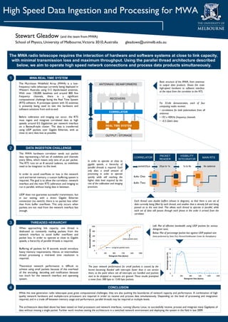
High Speed Data Ingestion and Processing for MWA

     Stewart Gleadow (and the team from MWA)
     School of Physics, University of Melbourne, Victoria 3010, Australia                                                                 gleadows@unimelb.edu.au


 The MWA radio telescope requires the interaction of hardware and software systems at close to link capacity,
  with minimal transmission loss and maximum throughput. Using the parallel thread architecture described
     below, we aim to operate high speed network connections and process data products simultaneously.


 1               MWA REAL TIME SYSTEM
                                                                                                                                                                                  Basic structure of the MWA, from antennas
       The Murchison Widefield Array (MWA) is a low-                                                        ANTENNAS / BEAMFORMERS                                                 to output data products. Shows the main
       frequency radio telescope currently being deployed in
                                                                                                                                                                                  high-speed hardware to software interface
       Western Australia using 512 dipole-based antennas.
                                                                                                                                                                                  at the input from the correlator to the RTS.
       With over 130,000 baselines and around 800 fine
                                                                           HARDWARE

       frequency channels, there is a significant
       computational challenge facing the Real Time System                                                           RECEIVERS
       (RTS) software. A prototype system with 32 antennas                                                                                                                        For 32-tile demonstration, each of four
       is presently being used to test the hardware and                                                                                                                           computing nodes receives:
       software solutions from end-to-end.
                                                                                                                                       •  correlations for both polarizations from all
                                                                                                                    CORRELATOR
                                                                                                                                                                                  antennas
       Before calibration and imaging can occur, the RTS                                                                                                                          •  192 x 40KHz frequency channels
       must ingest and integrate correlated data at high                                                                                                                          •  ~0.5 Gbit/s data
                                                                           SOFTWARE


       speeds; around 0.5 Gigabit/sec per network interface
       on a Beowulf-style cluster. The data is transferred                                                     REAL TIME SYSTEM
       using UDP packets over Gigabit Ethernet, with as
       close to zero data loss as possible.
                                                                                                               OUTPUT / STORAGE


 2           DATA INGESTION CHALLENGE
       The MWA hardware correlator sends out packet
       data representing a full set of visibilities and channels                                                                                                                  PACKET                                      VISIBILITY
                                                                                                                                                        CORRELATOR                                                                                         MAIN RTS
       every 50ms, which means only tens of µs per packet.                                                                                                                        READER                                    INTEGRATOR
                                                                     In order to operate at close to
       The RTS runs on an 8 second cadence, so visibilities          gigabit speeds, a hierarchy of
       need to be integrator to this level.
                         parallel threads is required. Each                                                    packet/20µs           20µs to 1s                                     1s to 8s                   8s cadence
                                                                     only does a small amount of
       In order to avoid overflows or loss in the network             processing in order to operate
       card and kernel memory, a custom buffering system is          quickly while still reaching the                                               Buffer One:
       required. The goal is to allow the correlator, network        higher data level required by the
       interface and the main RTS calibration and imaging to         rest of the calibration and imaging                                            Buffer Two:
       run in parallel, without losing data in between.
             processes.

       UDP does not guarantee successful transmission, but
       in our testing, with a direct Gigabit Ethernet
       connection (no switch), there is no packet loss other                                                                                            Each thread uses double buffers (shown in diagram), so that there is one set of
       than from buffer overflows. This only occurs when                                                                                                 data currently being filled by each thread, and another that is already full and being
       packets are not read from the network interface fast                                                                                             passed on to the next level. This allows each thread to operate in parallel, while
       enough.
                                                                                                                                         each set of data still passes through each phase in the order it arrived from the
                                                                                                                                                        correlator.


 3                THREADED HEIRARCHY
                                                                                              1000
                                                                       Left: Plot of effective bandwidth using UDP packets for various
       When approaching link capacity, one thread is                                                                                                                      datagram sizes.
                                                                      Bandwidth (Mbit/sec)


       dedicated to constantly reading packets from the                                        800
                                                                                                                                                                          Below: Plot of percentage packet loss against UDP payload size.
       network interface to avoid buffer overflows and                                          600
                                                                       (tests performed by Steve Ord, Harvard-Smithsonian Center for Astrophysics)
       packet loss. In order to operate at close to Gigabit                                                                         (new packet size)
       speeds, a hierarchy of parallel threads is required.
                                   400

                                                                                               200
                                                                                                                       (original packet size)
       Buffering all packets for 8 seconds would introduce                                                                                                                                                       18
                                                                                                 0
       heavy memory requirements. Hence, an intermediate
                                                                                                                                                                                          Percentage Loss (%)


                                                                                                      0
     400
       800
      1200
         1600
       2000
                                                15
       thread processing a mid-level time resolution is                                                             Datagram Size (bytes)
                                                                                                                                                                                                                 12
       required.
                                                                                                                                                                                                                  9

                                                                                                                                                                                                                  6
       Theoretical network performance is difficult to                The poor network performance for small packets is caused by the
       achieve using small packets because of the overhead           kernel becoming flooded with interrupts faster than it can service                                                                            3
       of the encoding, decoding and notification because             them, to the point where not all interrupts are handled and packets                                                                          0
       too much for the network interface and operating              start to be dropped as requests are ignored. These results prompted                                                                               0
    400
        800
      1200
      1600
     2000
       system.
                                                      a move from 388 byte to 1540 byte packets.
                                                                                                                    Datagram Size (bytes)


 4                                                                                                                  CONCLUSION
       While the new generation radio telescopes pose great computational challenges, they are also pushing the boundaries of network capacity and performance. A combination of high
       quality network hardware and multiple-core processors are required in order to receive and process data simultaneously. Depending on the level of processing and integration
       required, and in a trade off between memory usage and performance, parallel threads may be required at multiple levels.

       The architecture described above has been tested on Intel processors and network interfaces, running Ubuntu Linux, to successfully receive, process and integrate many Gigabytes of
       data without missing a single packet. Further work involves testing the architecture in a switched network environment and deploying the system in the field in late 2009.

           Melbourne Thermochronology

Multithreaded Data Transport

  • 1.
    High Speed DataIngestion and Processing for MWA Stewart Gleadow (and the team from MWA) School of Physics, University of Melbourne, Victoria 3010, Australia gleadows@unimelb.edu.au The MWA radio telescope requires the interaction of hardware and software systems at close to link capacity, with minimal transmission loss and maximum throughput. Using the parallel thread architecture described below, we aim to operate high speed network connections and process data products simultaneously. 1 MWA REAL TIME SYSTEM Basic structure of the MWA, from antennas The Murchison Widefield Array (MWA) is a low- ANTENNAS / BEAMFORMERS to output data products. Shows the main frequency radio telescope currently being deployed in high-speed hardware to software interface Western Australia using 512 dipole-based antennas. at the input from the correlator to the RTS. With over 130,000 baselines and around 800 fine HARDWARE frequency channels, there is a significant computational challenge facing the Real Time System RECEIVERS (RTS) software. A prototype system with 32 antennas For 32-tile demonstration, each of four is presently being used to test the hardware and computing nodes receives: software solutions from end-to-end. •  correlations for both polarizations from all CORRELATOR antennas Before calibration and imaging can occur, the RTS •  192 x 40KHz frequency channels must ingest and integrate correlated data at high •  ~0.5 Gbit/s data SOFTWARE speeds; around 0.5 Gigabit/sec per network interface on a Beowulf-style cluster. The data is transferred REAL TIME SYSTEM using UDP packets over Gigabit Ethernet, with as close to zero data loss as possible. OUTPUT / STORAGE 2 DATA INGESTION CHALLENGE The MWA hardware correlator sends out packet data representing a full set of visibilities and channels PACKET VISIBILITY CORRELATOR MAIN RTS every 50ms, which means only tens of µs per packet. READER INTEGRATOR In order to operate at close to The RTS runs on an 8 second cadence, so visibilities gigabit speeds, a hierarchy of need to be integrator to this level. parallel threads is required. Each packet/20µs 20µs to 1s 1s to 8s 8s cadence only does a small amount of In order to avoid overflows or loss in the network processing in order to operate card and kernel memory, a custom buffering system is quickly while still reaching the Buffer One: required. The goal is to allow the correlator, network higher data level required by the interface and the main RTS calibration and imaging to rest of the calibration and imaging Buffer Two: run in parallel, without losing data in between. processes. UDP does not guarantee successful transmission, but in our testing, with a direct Gigabit Ethernet connection (no switch), there is no packet loss other Each thread uses double buffers (shown in diagram), so that there is one set of than from buffer overflows. This only occurs when data currently being filled by each thread, and another that is already full and being packets are not read from the network interface fast passed on to the next level. This allows each thread to operate in parallel, while enough. each set of data still passes through each phase in the order it arrived from the correlator. 3 THREADED HEIRARCHY 1000 Left: Plot of effective bandwidth using UDP packets for various When approaching link capacity, one thread is datagram sizes. Bandwidth (Mbit/sec) dedicated to constantly reading packets from the 800 Below: Plot of percentage packet loss against UDP payload size. network interface to avoid buffer overflows and 600 (tests performed by Steve Ord, Harvard-Smithsonian Center for Astrophysics) packet loss. In order to operate at close to Gigabit (new packet size) speeds, a hierarchy of parallel threads is required. 400 200 (original packet size) Buffering all packets for 8 seconds would introduce 18 0 heavy memory requirements. Hence, an intermediate Percentage Loss (%) 0 400 800 1200 1600 2000 15 thread processing a mid-level time resolution is Datagram Size (bytes) 12 required. 9 6 Theoretical network performance is difficult to The poor network performance for small packets is caused by the achieve using small packets because of the overhead kernel becoming flooded with interrupts faster than it can service 3 of the encoding, decoding and notification because them, to the point where not all interrupts are handled and packets 0 too much for the network interface and operating start to be dropped as requests are ignored. These results prompted 0 400 800 1200 1600 2000 system. a move from 388 byte to 1540 byte packets. Datagram Size (bytes) 4 CONCLUSION While the new generation radio telescopes pose great computational challenges, they are also pushing the boundaries of network capacity and performance. A combination of high quality network hardware and multiple-core processors are required in order to receive and process data simultaneously. Depending on the level of processing and integration required, and in a trade off between memory usage and performance, parallel threads may be required at multiple levels. The architecture described above has been tested on Intel processors and network interfaces, running Ubuntu Linux, to successfully receive, process and integrate many Gigabytes of data without missing a single packet. Further work involves testing the architecture in a switched network environment and deploying the system in the field in late 2009. Melbourne Thermochronology