Downloaded 42 times
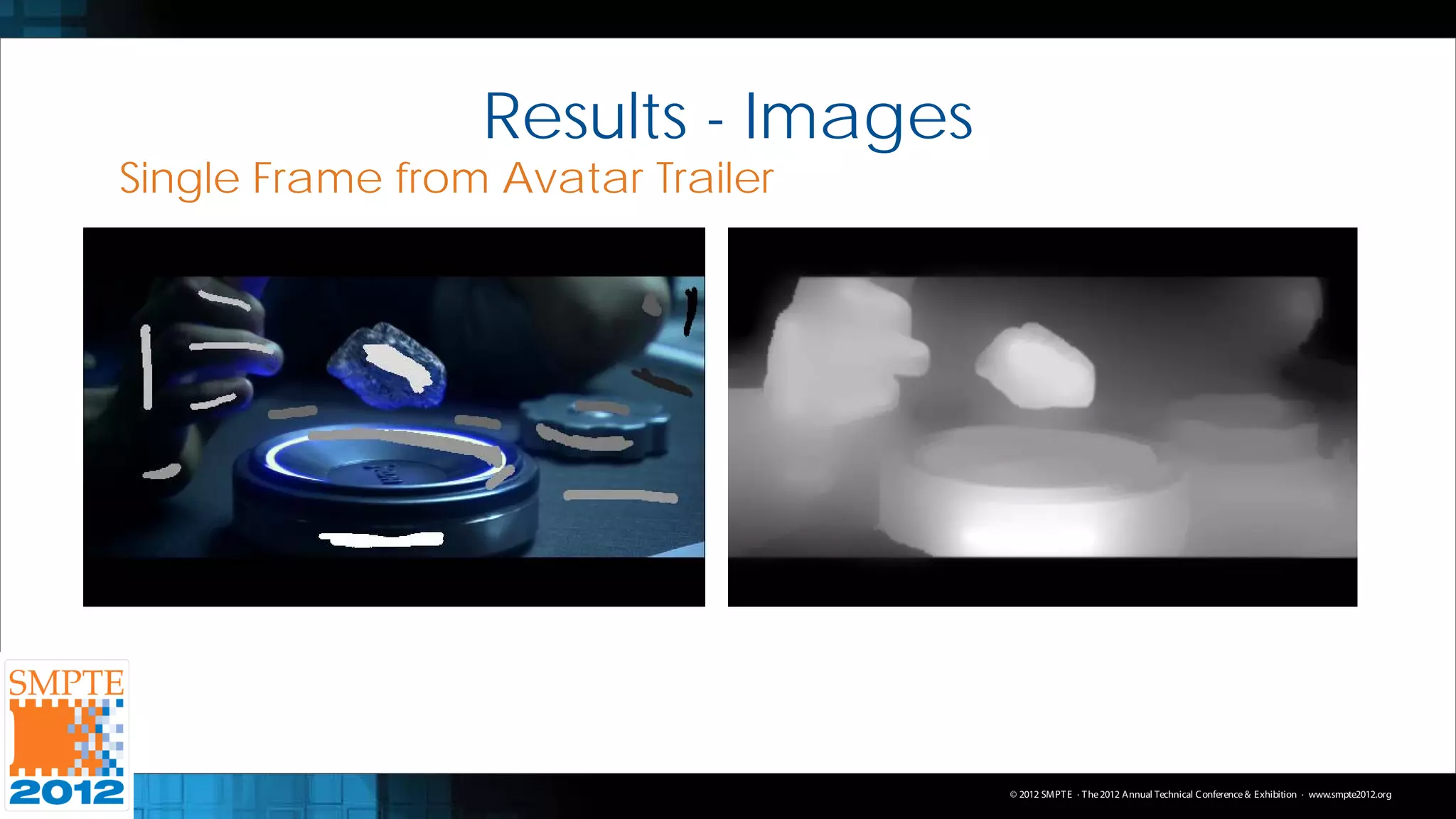
![Conversion Framework – Images
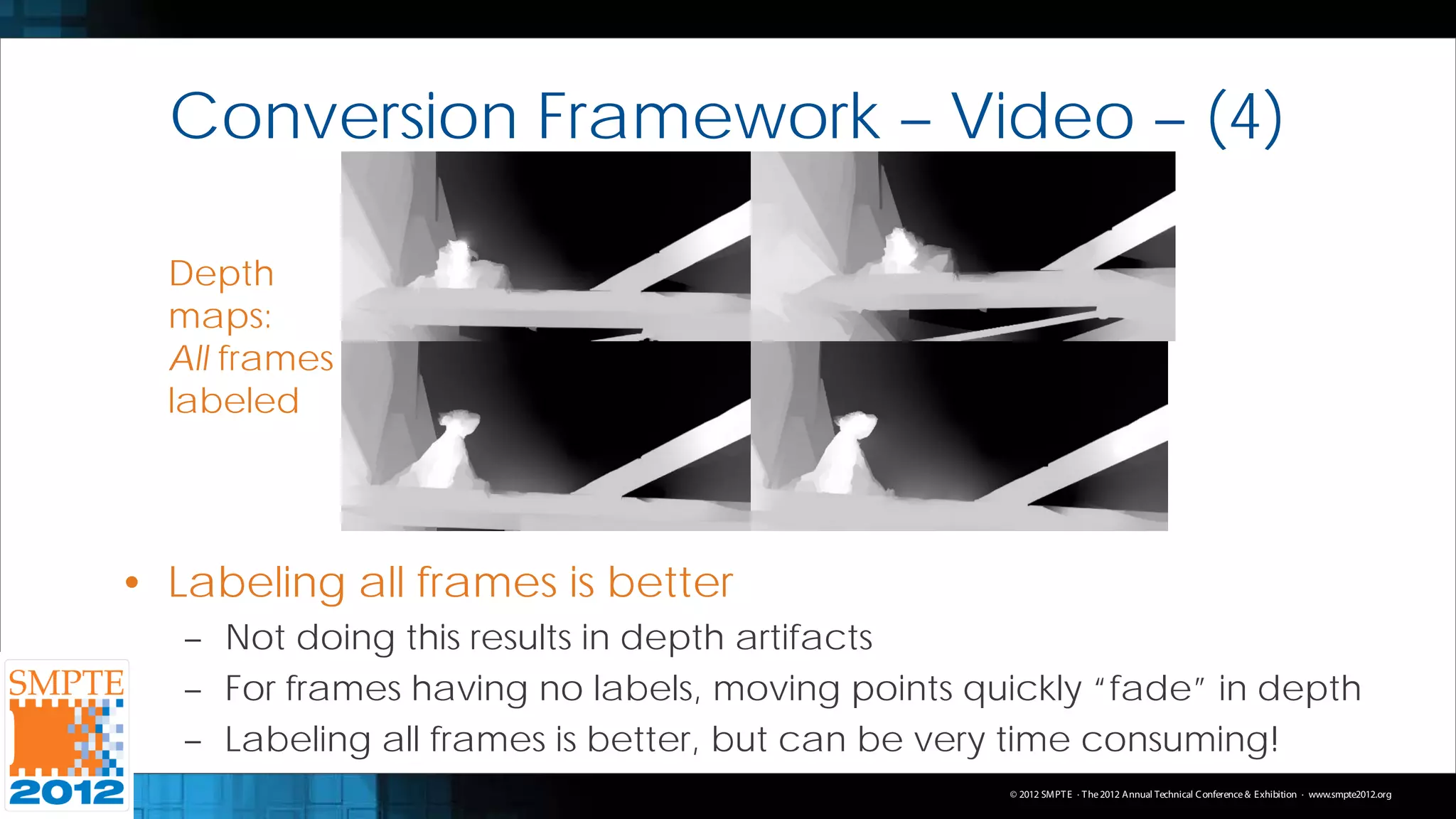
• Random Walks: Energy Minimization Scheme
– Starting from a user-defined label, what is the likelihood
of a random walker visiting all unlabeled pixels in image
– Goal: Classify every pixel to belong to one of K labels
– Pixel gets the label generating the highest likelihood
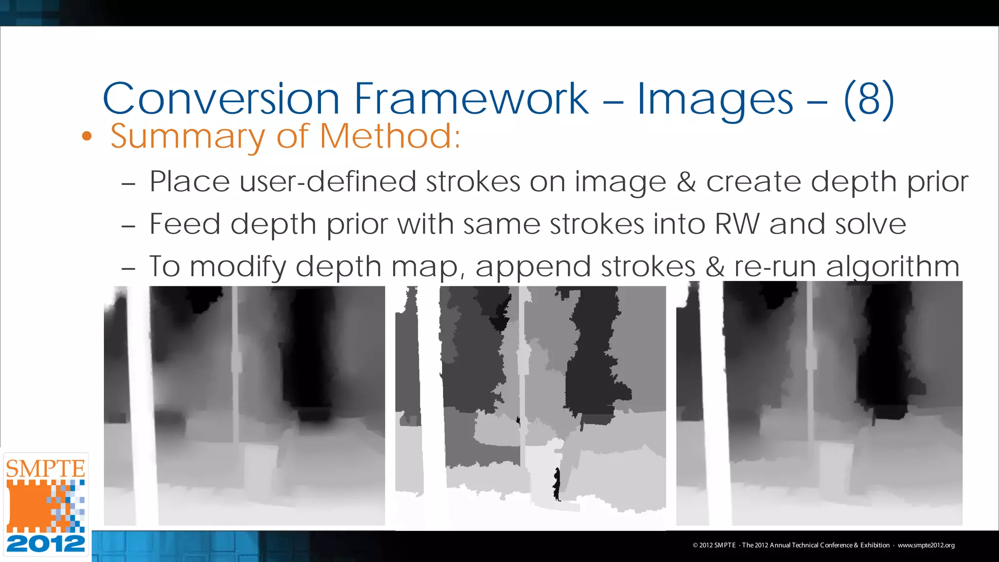
• Modify Random Walks to create depth maps
– Likelihoods are probabilities: Spans the set [0,1]
– User-defined depths and solved depths spans same set
– Goal is to solve for one label: The depth!
© 2012 SMPT E · T he 2012 Annual Technical C onference & Exhibition · www.smpte2012.org](https://image.slidesharecdn.com/raysmpte2012slides-120922093501-phpapp01/75/Unconstrained-2D-to-Stereoscopic-3D-Image-and-Video-Conversion-using-Semi-Automatic-Energy-Minimization-Techniques-6-2048.jpg)
![Conversion Framework – Images – (2)
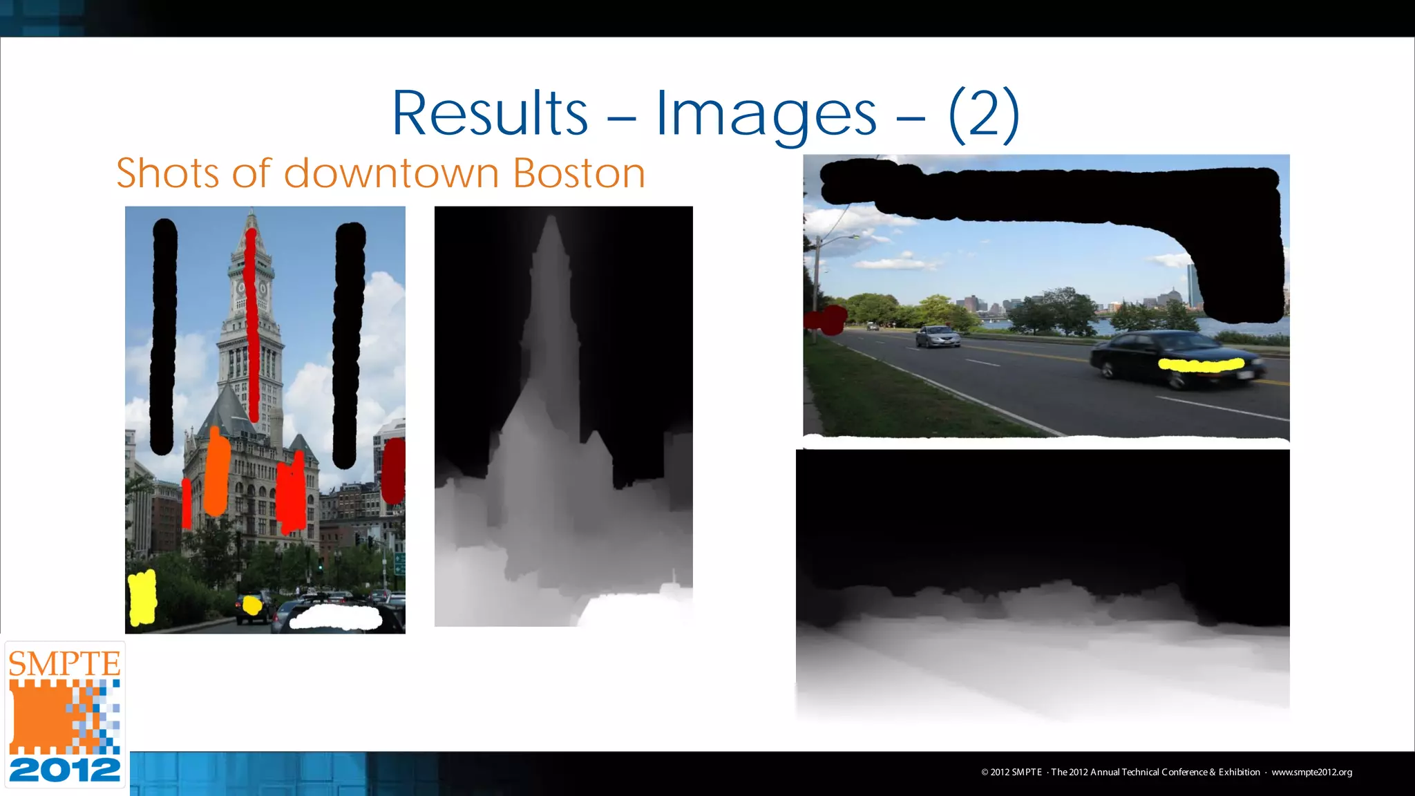
– Use Scale-Space Random Walks in our framework
• Pyramidal sampling scheme, with Random Walks applied to
each resolution Merged via Geometric Mean
– User chooses values from [0,1] and brushes over image
– 0: Dark intensity / color, 1: Light intensity / color
– Resulting solved probabilities are directly used as depths
• Is this valid?
– Yes! Psych. study done at Tel Aviv Uni. in Israel
– As long as the user is perceptually consistent in marking
© 2012 SMPT E · T he 2012 Annual Technical C onference & Exhibition · www.smpte2012.org](https://image.slidesharecdn.com/raysmpte2012slides-120922093501-phpapp01/75/Unconstrained-2D-to-Stereoscopic-3D-Image-and-Video-Conversion-using-Semi-Automatic-Energy-Minimization-Techniques-7-2048.jpg)
![Conversion Framework – Images – (5)
• NB: Making depth maps = Segmentation Problem
– Specifically, a multi-label segmentation problem
– But! Graph Cuts: Binary segmentation problem (FG/BG)
– Graph Cuts also has an integer labeling, not from [0,1]
• Must modify above to become multi-label
– Each unique user-defined label is given an integer label
– Binary segmentation is performed for each label
• FG: Label in question, BG: All of the other labels
– Rest of the pixels are those we wish to label
© 2012 SMPT E · T he 2012 Annual Technical C onference & Exhibition · www.smpte2012.org](https://image.slidesharecdn.com/raysmpte2012slides-120922093501-phpapp01/75/Unconstrained-2D-to-Stereoscopic-3D-Image-and-Video-Conversion-using-Semi-Automatic-Energy-Minimization-Techniques-10-2048.jpg)
![Conversion Framework – Images – (7)
• But! We can make use of this
– Merge Random Walks & Graph Cuts together
– Create a depth prior: An initial depth map estimate
– This is essentially Graph Cuts!
– We merge by feeding depth prior as additional information into RW
• Before we merge…
– Depth maps for RW and GC must be compatible with each other
• RW has depths of [0,1], GC has integer labels
– Map the user-defined labels from RW of set [0,1] to an integer set
– Perform Graph Cuts on using this integer set, and map the integer
set back to the set of [0,1] Use a lookup table to do this
© 2012 SMPT E · T he 2012 Annual Technical C onference & Exhibition · www.smpte2012.org](https://image.slidesharecdn.com/raysmpte2012slides-120922093501-phpapp01/75/Unconstrained-2D-to-Stereoscopic-3D-Image-and-Video-Conversion-using-Semi-Automatic-Energy-Minimization-Techniques-12-2048.jpg)
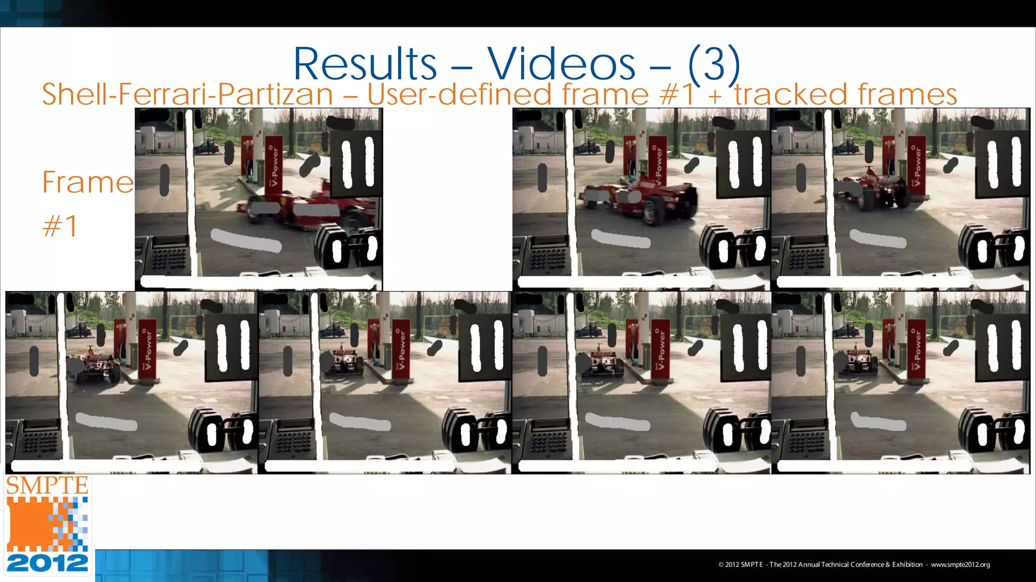
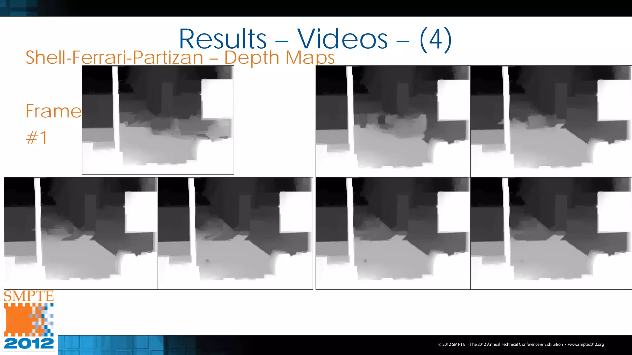
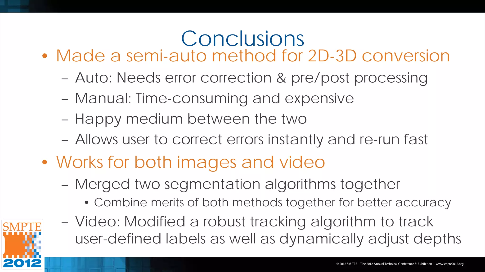

The document presents a semi-automatic method for converting 2D images and videos into 3D using energy minimization techniques, focusing on the frameworks of random walks and graph cuts. The approach seeks to reduce user effort in labeling while maintaining accuracy in depth mapping, which is crucial for successful 2D to 3D conversion. Results demonstrate the effectiveness of this method in improving conversion accuracy while addressing challenges in video depth tracking and labeling.


![[CVPR2020] Simple but effective image enhancement techniques](https://cdn.slidesharecdn.com/ss_thumbnails/simplebuteffectiveimageenhancementtechniques-200617034047-thumbnail.jpg?width=640&height=640&fit=bounds)


![Coded Agents – with UiPath SDK + LangGraph [Virtual Hands-on Workshop]](https://cdn.slidesharecdn.com/ss_thumbnails/codedagentsdeck-251215155422-5497c599-thumbnail.jpg?width=640&height=640&fit=bounds)


