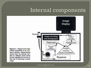
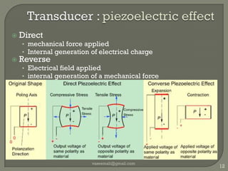
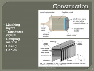
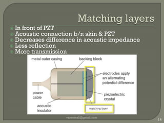
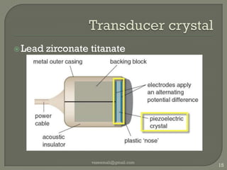
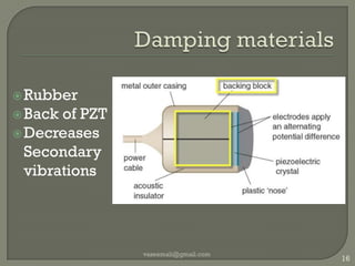
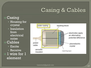
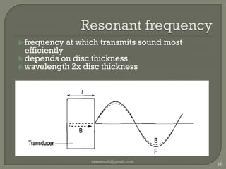
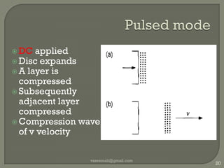
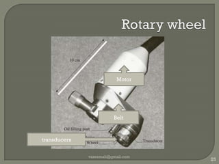
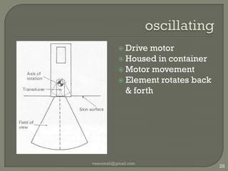
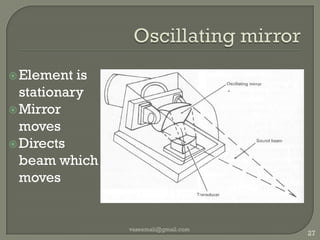
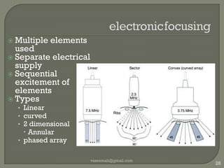
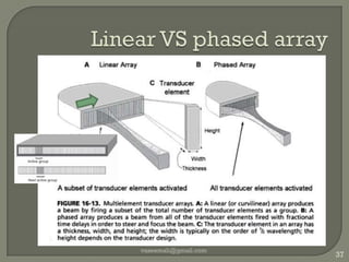
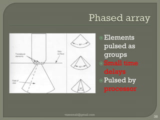
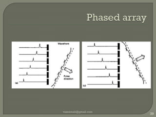
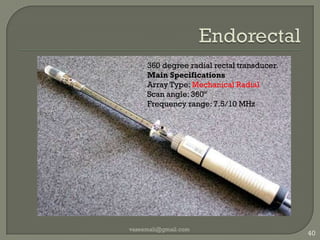
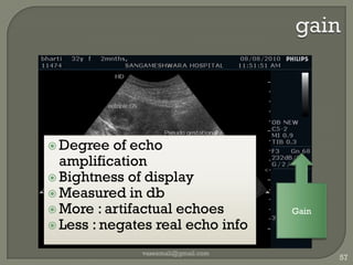
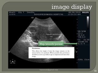
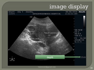
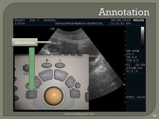
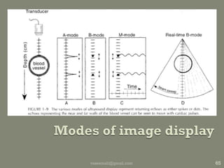
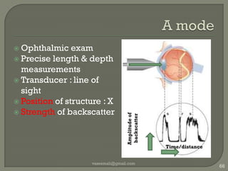
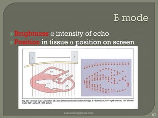
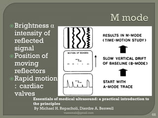
Instrumentation & KnobologyMODERATORSDR SURESH MASIMADEDR SHIVANAND MELKUNDI1vaseemali@gmail.com
The battle!vaseemali@gmail.com2
Why study ultrasoundvaseemali@gmail.com3Bread and butter!
comparisionvaseemali@gmail.com4
Piezoelectric effect : history1880 piezoelectric effect : Pierre Curie and Jacques Curie.Curie temperature1917, SONAR, Paul Langevin ultrasonic submarine detector.Post World War II :“AT cut” crystal barium titanatelead zirconatetitanatevaseemali@gmail.com5
vaseemali@gmail.com6
vaseemali@gmail.com7
Machine externallyvaseemali@gmail.com8MonitorSpeakerKeyboard Probes CPU
Internal componentsvaseemali@gmail.com9
Ultrasound gelContentsCarbomerEDTAPropylene glycolTrolamineDon’t adjust gain till gel is appliedApply gel on both sides of plasticWhen nothing is available : use watervaseemali@gmail.com10
Transducer orientaionvaseemali@gmail.com11
Transducer : piezoelectric effectDirectmechanical force appliedInternal generation of electrical chargeReverseElectrical field appliedinternal generation of a mechanical forcevaseemali@gmail.com12
Construction vaseemali@gmail.com13Matching layers
Transducer crystal
Damping material
Casing
Cables Matching layersIn front of PZTAcoustic connection b/n skin & PZTDecreases difference in acoustic impedanceLess reflectionMore transmissionvaseemali@gmail.com14
Transducer crystalLead zirconatetitanatevaseemali@gmail.com15
Damping materialsRubberBack of PZTDecreases Secondary vibrationsvaseemali@gmail.com16
Casing & Cables CasingHousing for crystalInsulation from electrical noiseCablesExcite Receive1 wire for 1 elementvaseemali@gmail.com17
Thicknessto change f we change transducer .why?any f by applying AC of that fConcept of resonant frequencyvaseemali@gmail.com18
Resonant frequencyvaseemali@gmail.com19frequency at which transmits sound most efficientlydepends on disc thicknesswavelength 2x disc thickness
Pulsed modeDC appliedDisc expandsA layer is compressedSubsequently adjacent layer compressedCompression wave of v velocityvaseemali@gmail.com20
Continuous modeAC voltage appliedCrystal pulsed like pistonCompressions and rarefactionsWavelength Frequency vaseemali@gmail.com21
Near field(Fresnel zone) & far field(Fraunhofer zone)Near field :  inhomogeneous interferenceFar field : diverges Focal zoneBetween near and far fieldBest resolution vaseemali@gmail.com22
Mechanical  transducersObsoletePhysically moved for beam steeringUsed in 3D 4DTypes Rotary wheelOscillating transducerOscillating mirrorvaseemali@gmail.com23Diagnostic Ultrasound: Physics and Equipment edited by Peter R. Hoskins, Kevin Martin, Abigail Thrush
Rotary wheelOne or more elementsWheel like housingSmall transducer faceIntercostal access vaseemali@gmail.com24
Rotary wheelvaseemali@gmail.com25Motor Belttransducers
oscillating Drive motorHoused in containerMotor movementElement rotates back  & forthvaseemali@gmail.com26
Oscillating mirrorElement is stationaryMirror movesDirects beam which movesvaseemali@gmail.com27
electronicfocusingMultiple elements usedSeparate electrical supplySequential excitement of elementsTypes Linearcurved2 dimensionalAnnularphased arrayvaseemali@gmail.com28
Electronic focusingMounted on straight barElectronic pulsingFocal depthFocus at many FLGreater time delay b/n elements=shorter focal lengthvaseemali@gmail.com29
Multiple zone focusing2 focal zonesFocused in 2 pulsesFirst one focused at f1Second at f2vaseemali@gmail.com30
Linear VS Curved arrayLinear	curvedLarger area of pt contactWide field near the skinBetter quality imageSuperficial structuresSmall acoustic windowNarrow field near skinWide field at depthDetailing is lessvaseemali@gmail.com31
Evolution of arraysvaseemali@gmail.com32Medical imaging: principles, detectors, and electronics By Krzysztof Iniewski
1.5 D arrayMultiple(5-7) linear arraysBeam steering in Azimuthal planePhased : outer to innerFrame rate reductionvaseemali@gmail.com33The essential physics of medical imaging By Jerrold T. Bushberg
2D arrayMultiple rows of elementsVoxel instead of pixelObstetricsvaseemali@gmail.com34
2d arraysvaseemali@gmail.com35
Annular arrayElements in concentric ringsvaseemali@gmail.com36
Linear VS phased arrayvaseemali@gmail.com37
Phased arrayElements pulsed as groups Small time delaysPulsed by processorvaseemali@gmail.com38
Phased arrayvaseemali@gmail.com39
Endorectal vaseemali@gmail.com40360 degree radial rectal transducer.Main SpecificationsArray Type: Mechanical RadialScan angle: 360ºFrequency range: 7.5/10 MHz
endovaginalvaseemali@gmail.com41Array type: Convex ArrayScan angle: 120°Radius: 14 mmFrequency range: 3-7.5 MHz
“T" Style Intraoperativevaseemali@gmail.com42Array Type: Linear ArrayScan angle/width: 42mmFrequency range: 5-10 MHz
"I" Style Finger-Grip intraopvaseemali@gmail.com43design fits comfortably between the index and middle finger which allows for palpating organs and scanning at the same time.Array Type: Convex ArrayScan angle/width: 65°/20mmFrequency range: 3.75-10 MHz
End Fire Laparoscopicvaseemali@gmail.com44End-fire laparoscopic transducer that is perfect for CBD scanning and targeting lesions. Array Type: Phased ArrayScan angle/width: 90°Frequency range: 3-7.5 MHz
Micro Surgeryvaseemali@gmail.com45pediatric scanning CBD scanning. small vessels Array Type: Linear ArrayInsertion diameter: 10mmScan angle/width: 10mmFrequency range: 5-13 MHz
Motorized TEEvaseemali@gmail.com46cardiac anesthesia, cardiac surgery, or intensive care workArray type: Phased Array SectorScan angle: 90°Frequency range: 2-8 MHzInsertion Depth: 1000 mmDiameter: 12.5 mm
38mm for Regional Anesthesiavaseemali@gmail.com47slightly larger footprint 38mm
visualization of deeper structures
nerves
Infraclavicular
popliteal regions.
guide needle placement Main SpecificationsArray Type: Convex ArrayScan angle/width: 38mmFrequency range: 5-10MHz
Cardiac Phased Arrayvaseemali@gmail.com48Cardiac transducer Array type: Phased ArrayScan angle: 90°Frequency range: 2.5-5 MHz
intravascularvaseemali@gmail.com49Atheromatous plaqueAfter stenting
image displayvaseemali@gmail.com50
image displayvaseemali@gmail.com51Manufacturer
image displayvaseemali@gmail.com52Date/time
image displayvaseemali@gmail.com53Clinic info
image displayvaseemali@gmail.com54Patient  info
image displayvaseemali@gmail.com55Profile / Preset
image displayvaseemali@gmail.com56Transducer in use
gainDegree of echo amplificationBightness of displayMeasured in dbMore : artifactual echoesLess : negates real echo infovaseemali@gmail.com57Gain
image displayvaseemali@gmail.com58Map/smooth/persist
image displayvaseemali@gmail.com59depth
Annotation vaseemali@gmail.com60Annotation
Image tintingvaseemali@gmail.com61Golden hue is aesthetically pleasing to the eye
Shows excellent shadows and highlights. Left right invertvaseemali@gmail.com62
Up down invertvaseemali@gmail.com63
Split framevaseemali@gmail.com64Display 2 images side by sideComparison of echotexture
Modes of image display65vaseemali@gmail.com
A modeOphthalmic examPrecise length & depth measurementsTransducer : line of sightPosition of structure : XStrength of backscatter vaseemali@gmail.com66Amplitude of backscatterTime/distance
B modevaseemali@gmail.com67Brightnessα intensity of echoPosition in tissue α position on screen
M modeBrightness α intensity of reflected signalPosition of moving reflectorsRapid motion :  cardiac valvesvaseemali@gmail.com68Essentials of medical ultrasound: a practical introduction to the principles By Michael H. Repacholi, Dierdre A. Benwell
M modevaseemali@gmail.com69The essential physics of medical imaging By Jerrold T. Bushberg
M modeECG concurrentLine of sightvaseemali@gmail.com70
Real time USGSuccession of framesMotion of tissuesLine densityat least 100 per frameFrame rateDepth of viewvaseemali@gmail.com71
Frame rateMovie FR 25-30fpsTemporal resolutionNow >100 fps, TR 10msReal time 20-30fpsM mode : very high fpsHence LOS ,TR 0.1msBetter frame rateLess depthLess field of viewDepth X scan lines X frame rate =constantvaseemali@gmail.com72
Calipers/measureLengthArea Volume vaseemali@gmail.com73Calipers
Trackball Cursor motionGUI controlvaseemali@gmail.com74Track ball
ZoomMagnifies selected areaRead zoomDigital zoomNo changes in line densityWrite zoomOptical zoomIncreases scan line densityImproved resolutionvaseemali@gmail.com75
image displayvaseemali@gmail.com76Dynamic range Compress
Dynamic range/compressRatio of largest/smallest echoMeasured in dBFrom tissues 100-150dBDecreases as signals into USGRejection filter : rejects very small & very large echoesTGC60 dB at ADC level vaseemali@gmail.com77
Compress 60dB of interestDisplay : only 20dB brightness levelsNon linear amplifierMore gain for smaller signalsLiver texture: wide Obstetric: less Dark : amniotic fluidBright : bones vaseemali@gmail.com78
Power vaseemali@gmail.com79
Power Not the same as gainEnergy transferred to tissuesMore power : more tissue damageMeasured in watts/cm2ALARA : as low as reasonably allowableMore than 8 W/cm2 : therapeuticAIUM guidelines(SATA,SPTP)Doppler : excessive power levelsUse less powerQuick examinationvaseemali@gmail.com80
Gain vaseemali@gmail.com81Overall “brightness”Changes echo strength over entire image
Time gain compensationEach slider for a range of depthTop : superficialBottom : deepButtons at Center : average gainvaseemali@gmail.com82
Time gain compensationvaseemali@gmail.com83
Time gain compensationvaseemali@gmail.com84Springer handbook of acoustics By Thomas D. Rossing
Freeze and cine loopStops further image acquisitionDisplays current image vaseemali@gmail.com85
Cine loopTrack ballNot USG specificUsed in CT MRI PETStill images in successionPlayed back Dynamic movement :Cardiac  motionDoppler studiesRecorded as moviePhysician/cardiologist can view latervaseemali@gmail.com86
Image processorInterpolation between scan linesLog compressPost processingSpatial filteringReduce noiseEnhance edgesTemporal filtering : frame avg/persistReduces image noiseImage demonstrates a lagReduction in temporal resolutionvaseemali@gmail.com87
Scan converter (ADC)Echo : Analog waveAnalogueStorage CRTUnstable“drift” in settingsAnalog-Digital convertorDigital StableProcessingvaseemali@gmail.com88
Image displayDisplays : analogue inputModern machines: digital architectureDAC Input : digitalOutput : analogueBrightness Contrast vaseemali@gmail.com89
Image memory640 X 480 pixels256 gray shade levels¼ MB per imageColor images : Doppler imagingFreeze functionTemporary image storeArchiving : MLC Latest systems : internal storageHold many GB datavaseemali@gmail.com90
Image resolutionSpatial : 2 close objects as distinctAxial : along beam axisLateral : perpendicular to beam axisAzimuthal : perpendicular to beam & transducerContrast : two regions of different avg brightnessTemporal : distinguish events in timeReal time cant in cardiac valve motionFreedom from artifactsvaseemali@gmail.com91
Spatial resolutionvaseemali@gmail.com92elevationlateralaxialMedical imaging: principles, detectors, and electronics By Krzysztof Iniewski
Tickle UR brain!Why does the high frequency superficial probe have a high resolutionvaseemali@gmail.com93
Axial resolutionvaseemali@gmail.com94SPL=no of cycles X wavelengthThe essential physics of medical imaging By Jerrold T. Bushberg
Axial resolution95Ultrasound in cardiology By Kurt J. G. Schmailzl, Oliver Ormerodvaseemali@gmail.com
Lateral resolutionDepends on Beam widthUser controlledDepends on focusingvaseemali@gmail.com96The essential physics of medical imaging By Jerrold T. Bushberg
Azimuthal/elevation resolutionResolution in planePerpendicular to beam axisPerpendicular to transducerThickness of beamNo user controlFixed due to transducer thicknessvaseemali@gmail.com97

ultrasound Instrumentation physics