Downloaded 725 times


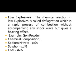
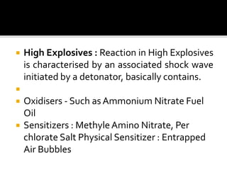


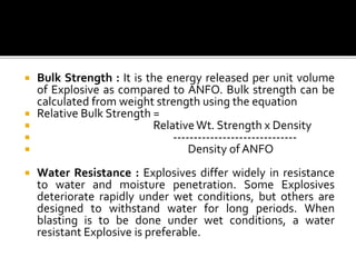
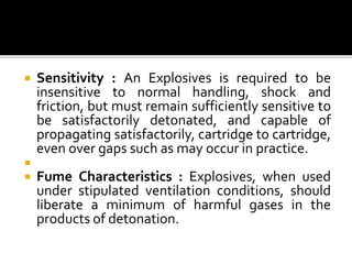


The document defines explosives as chemical compounds that produce large volumes of gas quickly when detonated and classifies them into low and high explosives. It elaborates on various characteristics of explosives, such as velocity of detonation, weight strength, sensitivity, and water resistance, highlighting the importance of each in different blasting operations. Additionally, it describes various blasting accessories and methods used in tunneling and rock blasting, along with safety considerations and specific applications for different types of explosives.


![detonator presentation[ mining technology].pptx](https://cdn.slidesharecdn.com/ss_thumbnails/detonatorppt-250801053603-2c97af9f-thumbnail.jpg?width=640&height=640&fit=bounds)


