This document provides an introduction to business modeling concepts and a comparison of the Unified Modeling Language (UML) and the Integration DEFinition (IDEF) family of languages for business modeling. It defines key terms like business models and processes. It also discusses how business models can provide requirements for information systems and support business improvement vs innovation. The document outlines some important business concepts and the relationship between business and software architecture.
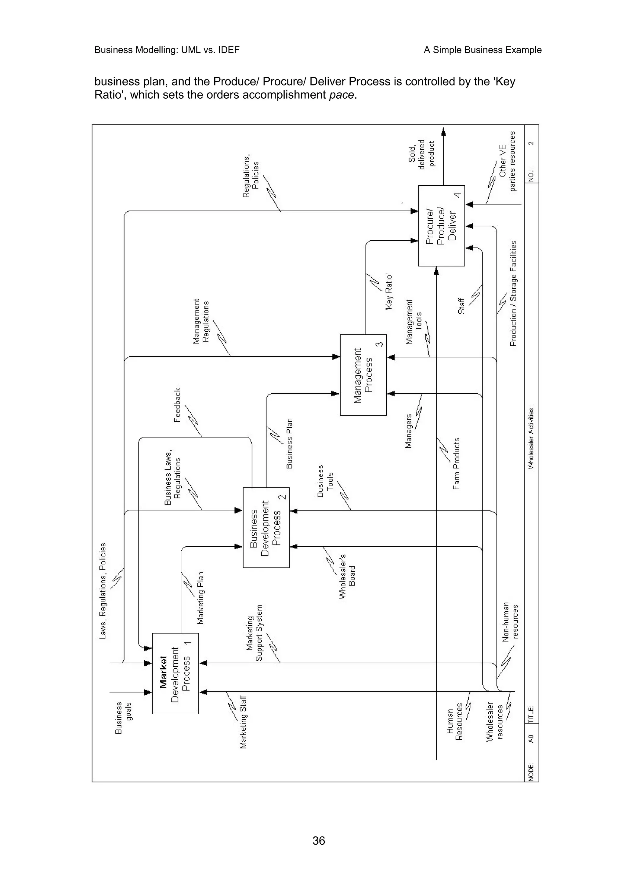
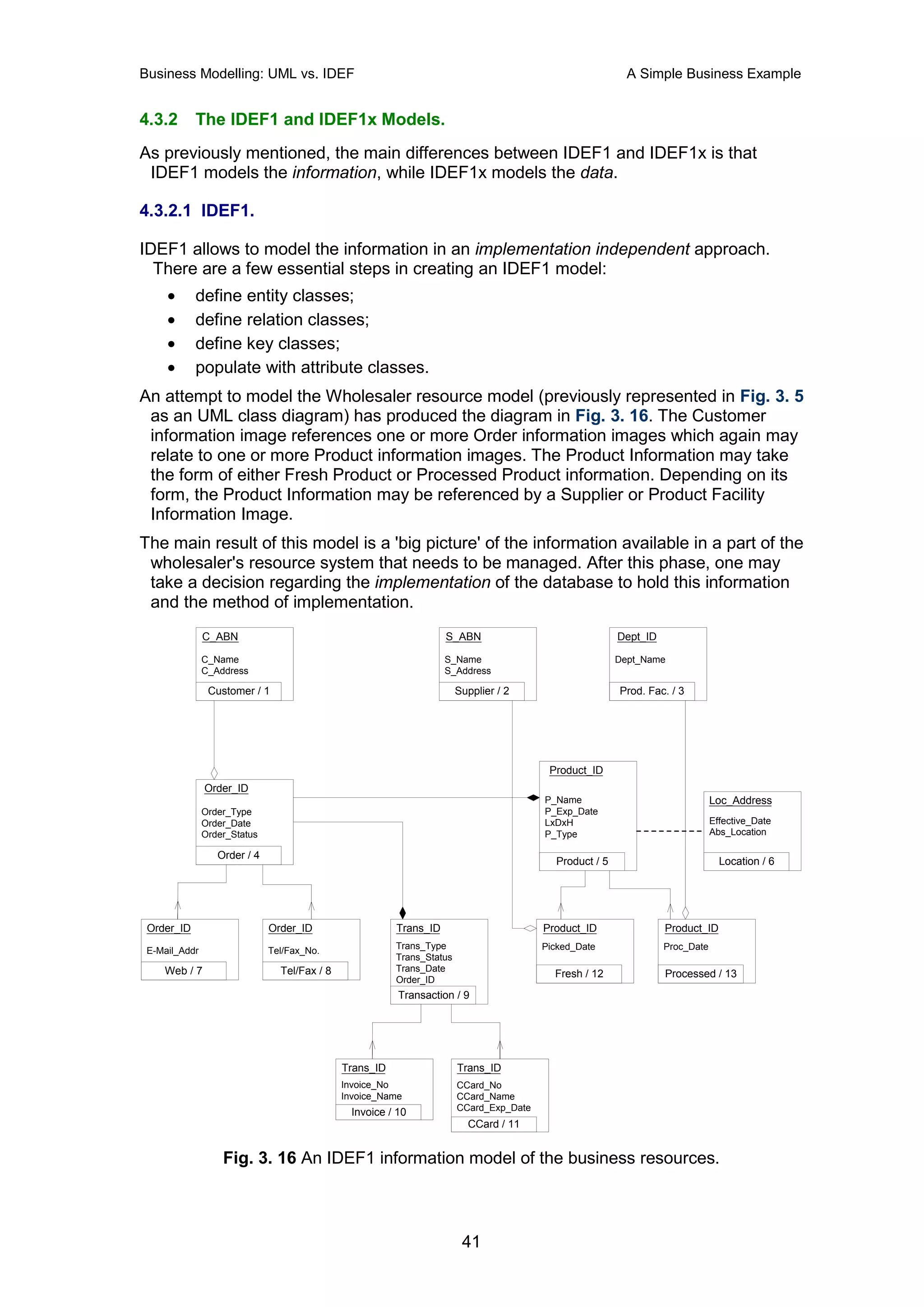
![Business Modelling: UML vs. IDEF A Simple Business Example
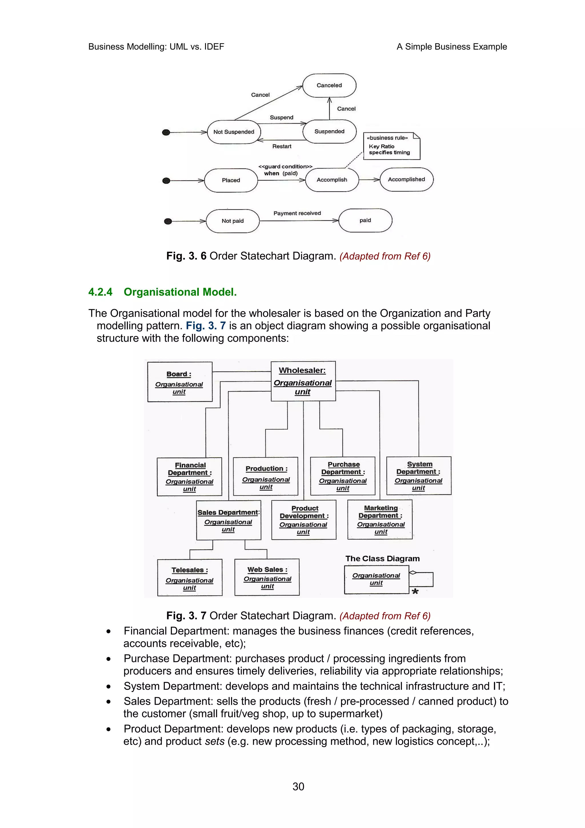
Fig. 3. 5 The wholesaler resources model.
The Product Data Management (PDM) and the Geographic Location patterns (Ref 6)
have been used to construct the resource model of the business. According to the
PDM pattern, the Product Set is a powertype for Product. An instance of the Product
Set may be 'canned fruit', and an instance of Product may be 'canned fruit pack no.
[barcode]' (or even a particular can of fruit depending on the necessary granularity).
Part of the resource modelling must also cover the order and item models, since they
are some of the most important resources for the business. A simple order statechart
is shown in Fig. 3. 6. An order may be placed, paid / not paid, (permanently)
cancelled, (temporarily) suspended, or accomplished.
29](https://image.slidesharecdn.com/umlvsidef-1254006096-phpapp02/75/U-M-Lvs-I-D-E-F-32-2048.jpg)


![[0201699613]visual modeling with rational rose 2000 and uml](https://cdn.slidesharecdn.com/ss_thumbnails/0201699613visualmodelingwithrationalrose2000anduml-121217215714-phpapp02-thumbnail.jpg?width=640&height=640&fit=bounds)


