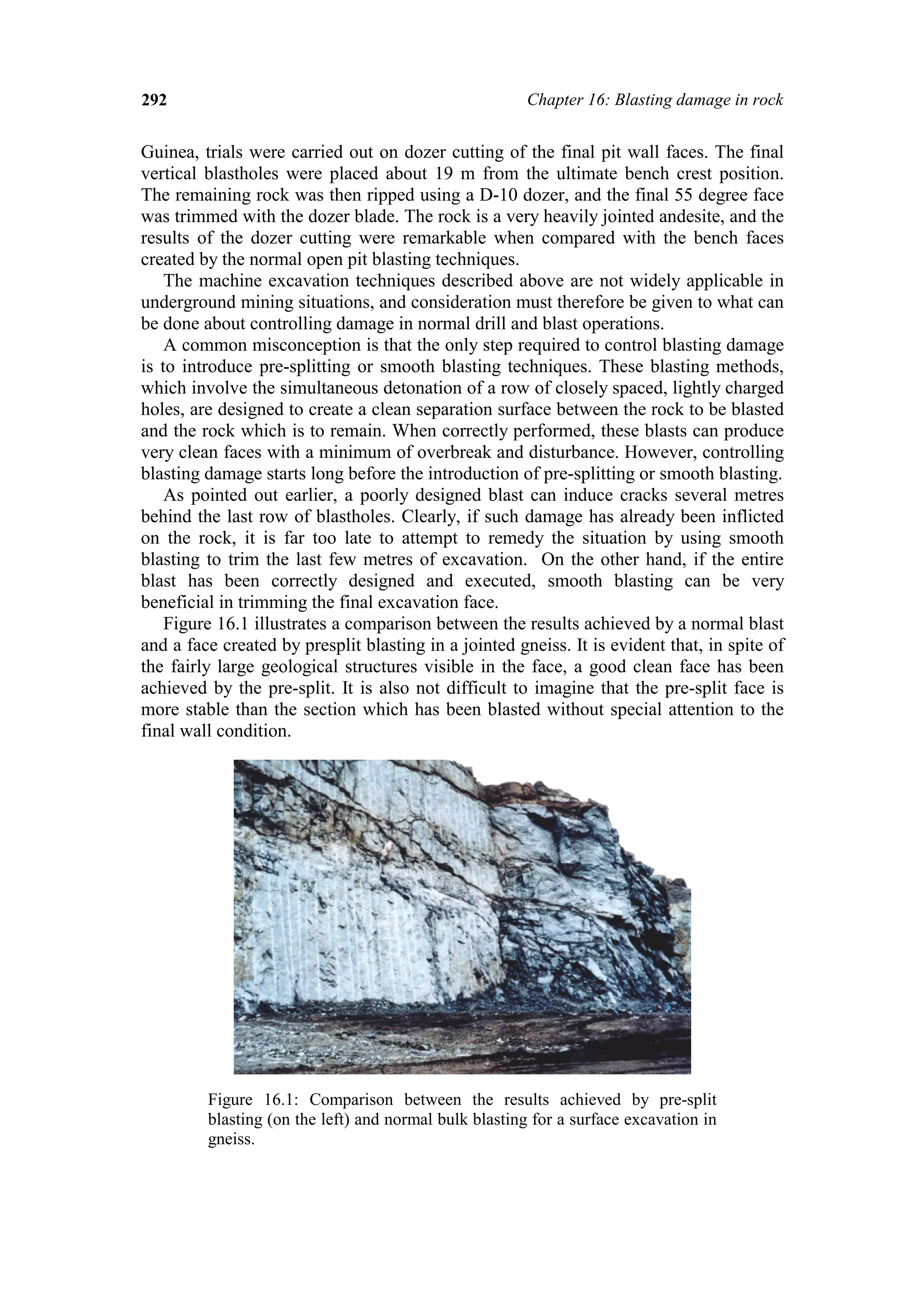
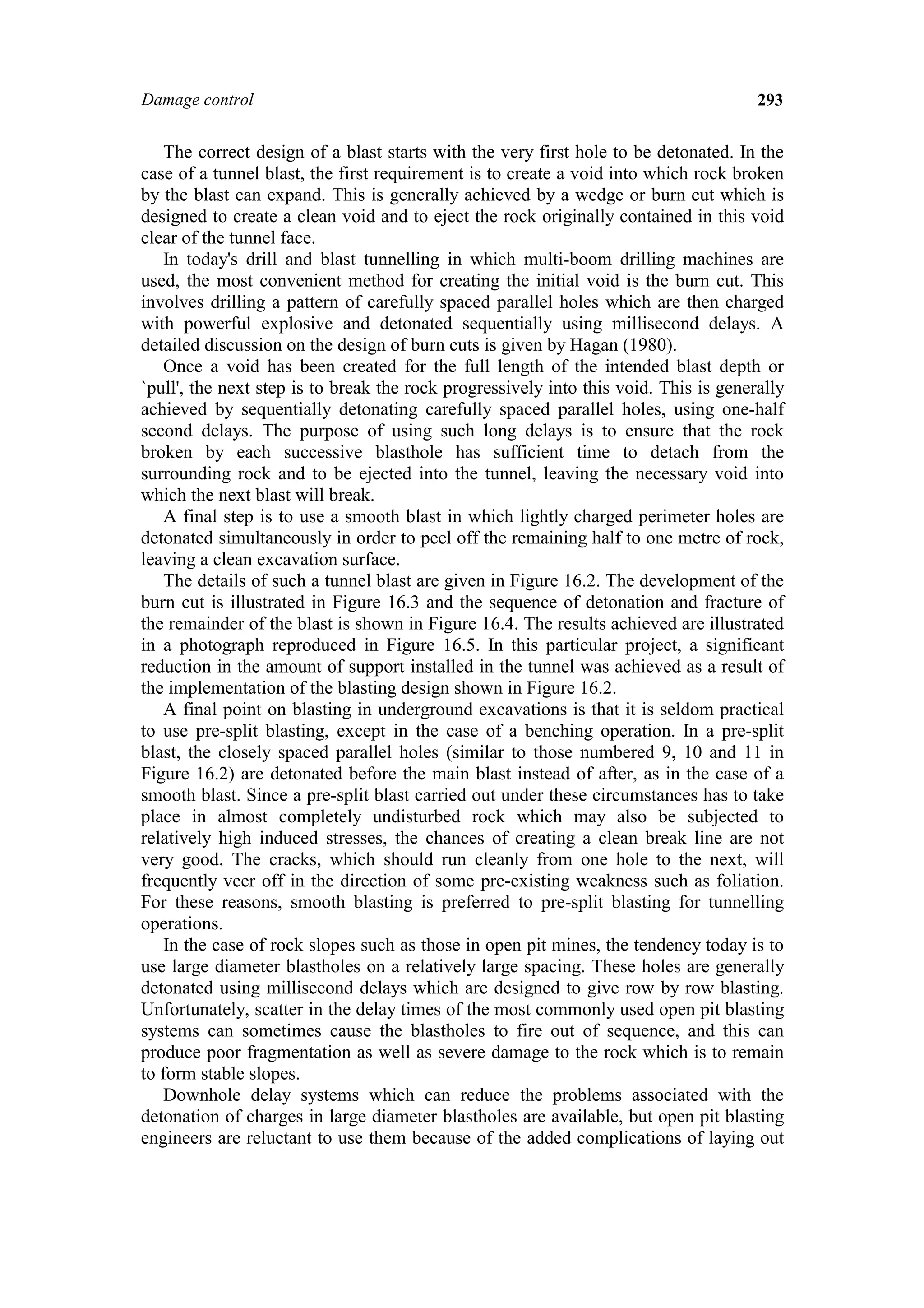
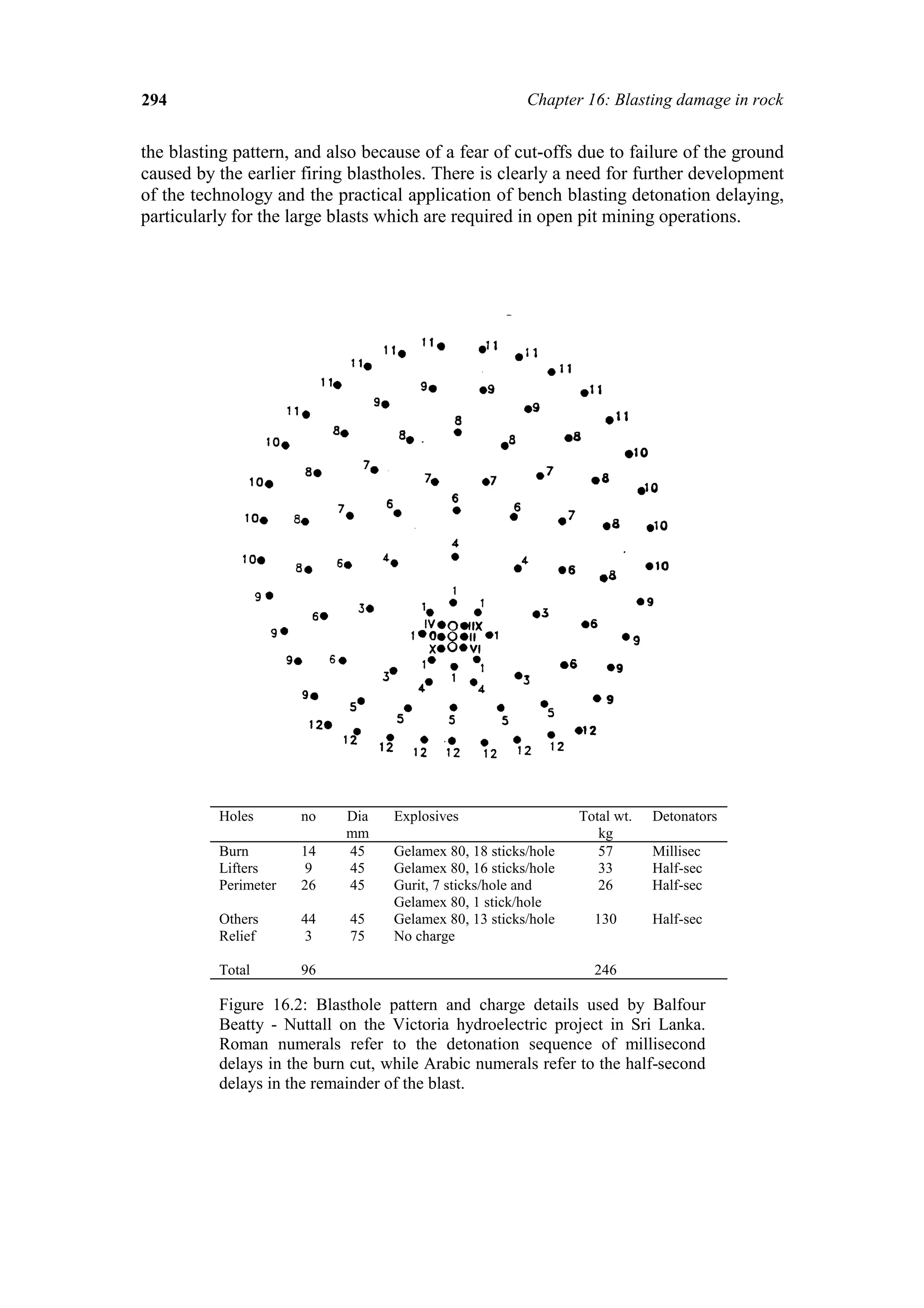
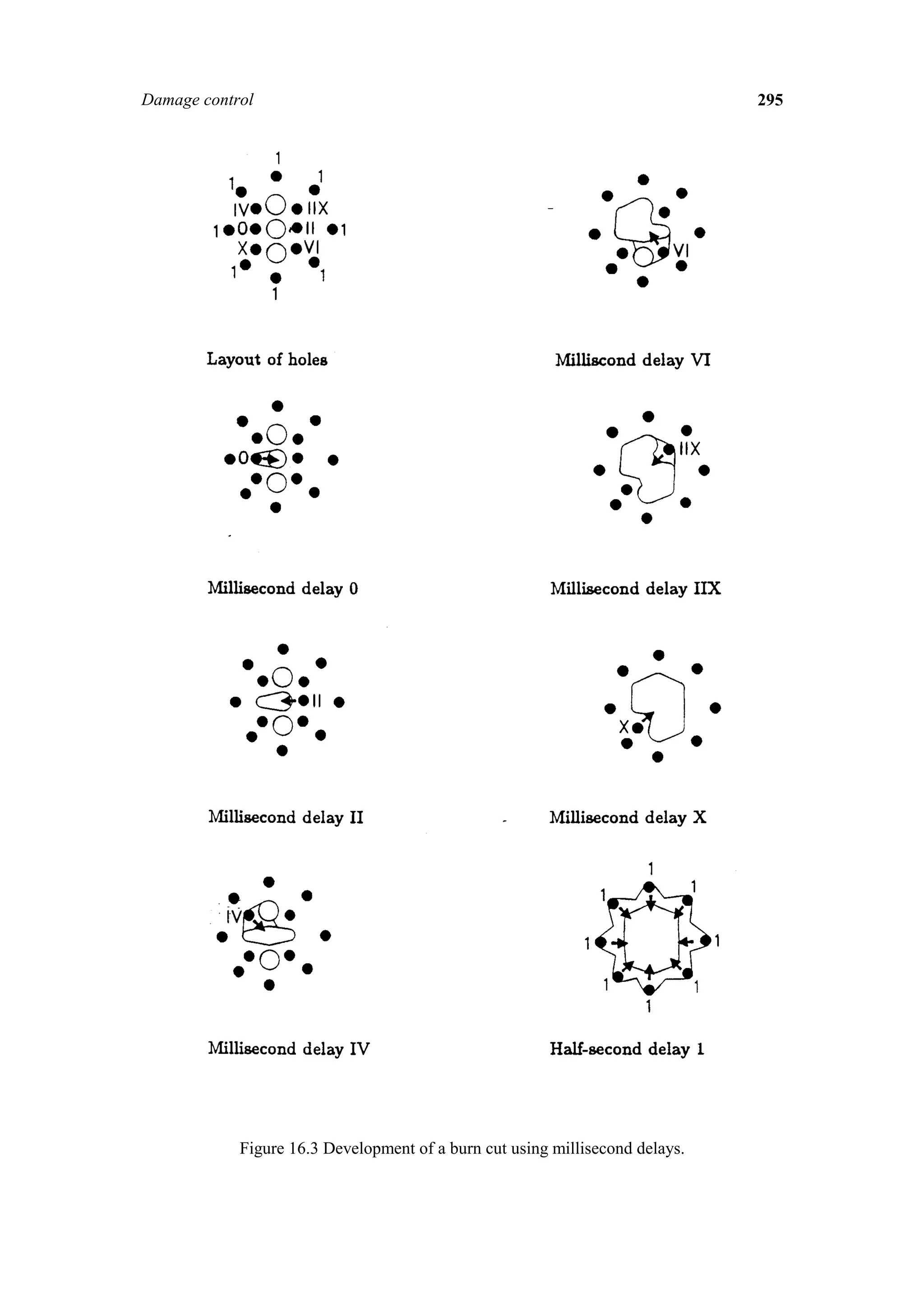
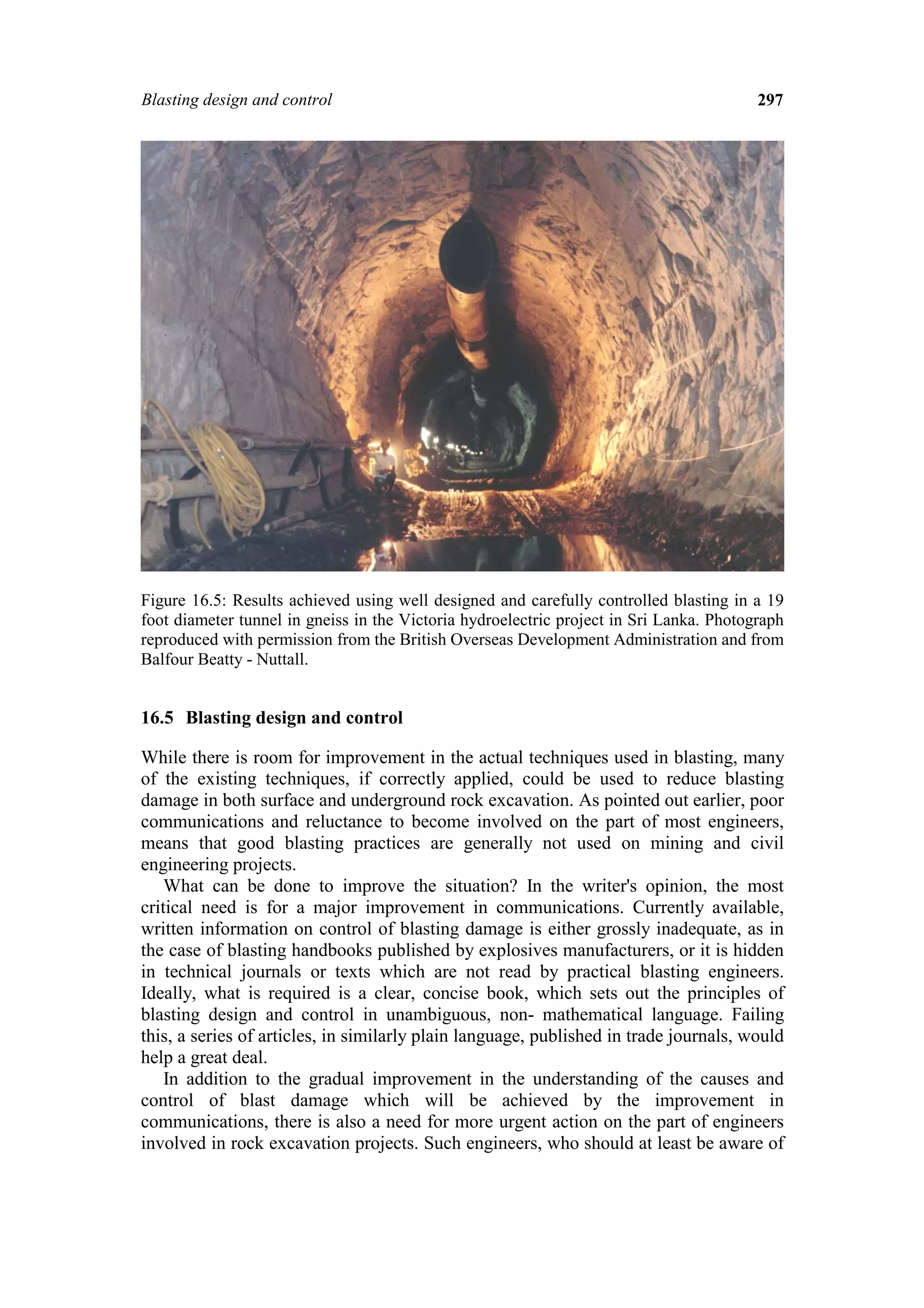
The document discusses blasting damage in rock excavations and methods to control it. It begins with a brief history of blasting and how the understanding of its effects on rock stability has lagged behind other areas of rock mechanics. Blasting can damage rock through dynamic stresses, gas pressure, and fracturing from the release of compressed rock. Precisely controlling blasting techniques from the initial cut through the full blast sequence is necessary to minimize damage extending several meters into the surrounding rock. Methods discussed include pre-splitting, smooth blasting, and the use of delays to allow broken rock to clear before subsequent holes detonate. Proper blasting design is crucial for ensuring the stability of underground excavations and rock slopes.
Control and Prediction of Blast Fragmentation and It's effect on the Comminut...James Dunford
This technical report discusses controlling and predicting blast fragmentation and its impact on comminution. Section 1 covers bench blast theory, including geometric controls, explosive properties, and rock mass properties. Section 2 discusses comminution theory, including the three laws of comminution and Bonds Law. Section 3 examines how varying geometric controls, explosive type, detonator choice, and delay timing can affect fragmentation. Optimizing these factors can improve comminution efficiency. The report then covers several models for predicting fragmentation and compares their benefits and limitations.
The document discusses techniques for open pit mining blasts, including:
- Major factors like attitude, communication, blast design, and geological effects influence blast efficiency
- Proper blast design considers uniform energy distribution, confinement, energy level, and design adjustments for conditions
- Geological effects like rock properties, structure, water, and seam orientations impact blasting results more than explosive properties
- Basic blast design considerations include bench height, hole diameter, burden, spacing, stemming, and decking
The New Austrian Tunneling Method (NATM) involves:
1) Creating initial support on tunnel openings to prevent deterioration.
2) Excavating in short sections and applying shotcrete and metal supports.
3) Monitoring deformation with various instruments to ensure tunnel stability.
This document discusses trends in underground mining methods. It notes that investments in new mines have increased dramatically in recent years and are expected to remain high. Global metal production has increased steadily each year to around 5,000 million tonnes annually, with 17% coming from underground mines. Underground mining techniques have advanced rapidly in recent decades through mechanization, allowing for larger volumes of rock to be excavated safely and efficiently. Contractors now play a larger role in underground development and infrastructure works.
This document discusses rock fragmentation in mining through blasting. It describes the objectives of fragmentation and factors that control fragment size, such as specific charge, spacing and burden. It explains the mechanisms of blasting including detonation shock waves and gas pressure. Methods for quantifying and optimizing fragmentation are provided, such as mean fragment size and oversize content. A case study reports on blasting results from a Tata Steel mine in India. The document also discusses secondary blasting and modeling fragmentation using the Kuz-Ram model and software.
Research on mean partical size after drilling & blasting by Abhijit palAbhijit Pal
Rock fragmentation is important for mining efficiency. Factors like blast design, explosives used, and rock properties affect fragment size. A report from Tata Steel showed mean fragment sizes ranging from 15-49 cm for overburden and coal over 10 days. Software can analyze muckpile photos and provide fragmentation data like size distributions and percentages. Understanding fragmentation allows optimizing blasting for maximum production.
Explosives, Theory Of Breakage And Blasting Operationspartha sharma
This document discusses explosives and blasting operations. It defines different types of explosives and their ingredients and functions. It explains how to compare explosives based on their properties like strength, detonation velocity, density etc. It describes drilling systems and the theory of rock breakage through radial cracking and flexural rupture. Finally, it discusses blast design factors and different controlled blasting techniques like line drilling, cushion blasting, smooth-wall blasting and pre-splitting used to control overbreak.
This document discusses several controlled blasting techniques used to control blasting results, including line drilling, pre-splitting, cushion blasting, smooth blasting, air-decking, and muffle blasting. It focuses on describing the pre-splitting technique, which involves drilling a row of holes along the final excavation line, loading them with light explosives charges, and firing them before the main blast to create a fracture zone and prevent overbreak of the wall. The document provides details on parameters for pre-splitting like hole spacing, loading density, and linear charge concentration based on hole diameter. It emphasizes the importance of selecting the right parameters for the specific rock conditions when using pre-splitting.
New burn cut blast design in drives enhances drilling blasting efficiency wit...partha sharma
A new Burn-Cut blast pattern has been designed for drives, declines and ramps in underground metal mines, to replace a design (of Decked-Burn with more number of holes), which was giving number of blast failures, such as ‘Under_Blast’ - difficult to handle. The new Burn-cut design contains less number of blast-holes and Reamer than earlier Decked-Burn-cut. Decked system has been removed to make the charging operation easier. This enables to increase explosives energy in a hole and to reduce stemming length in order to eliminate above blast failures. Moreover, requirement of Detonators is reduced, as Decked system has been abolished. Total explosives quantity has been reduced marginally. Thus, drilling efficiency and cost effectiveness has been achieved. Entire process has been done by changing the original pattern / system in three phases.
The document discusses factors that influence blast design and describes the various components of bench blast design. It provides background on how the blast design must balance parameters to achieve desired fragmentation. The factors affecting blast design are classified as uncontrollable geological variables and controllable variables like hole diameter, burden, spacing, stemming, and firing system. Formulas are provided for calculating the values of bench blast design components like burden, spacing, subdrilling, hole depth, and stemming height using the Ash approach. Examples are worked out using initial assumptions of a 115mm hole diameter, emulsion explosive, and medium rock density. The document concludes with discussing powder factor calculation and the basic steps for successful blast design.
The document discusses the basics of drilling for mining operations. It covers topics such as inclined hole drilling, drilling parameters like blasthole diameter, burden, spacing, charge length and stemming. It also discusses evaluating drill performance, including drill hole deviation, drill machine navigation systems, benefits of monitoring drill performance such as higher penetration rates and accuracy of data. Drill monitoring allows collection of production statistics, maintenance information, and consumable tracking to assess drillability.
(1) Rotary drilling involves rotating a drill bit to break rock using either a scraping or crushing action. Compressed air is used to remove cuttings from the hole.
(2) Key factors that influence the penetration rate of rotary drills include the rotation speed of the drill bit, the pull-down weight applied to the bit, and the size and design of the drill bit itself.
(3) Larger drill bits and higher air velocities are generally better for drilling productivity but can increase wear on stabilizers and drill pipes. Choosing equipment for single-pass drilling can boost productivity but requires more stable drill masts.
ANFO, Emulsion and Heavy ANFO blends - Useful explosive and blasting agent fo...partha sharma
AN being oxygen positive, is often used as oxygen supplier in addition to being an explosive base. It forms the explosive base in ANFO (Ammonium Nitrate – Fuel Oil) explosives,which are now widely used.
This presentation is mainly about the study of slope failure using FLAC 3D software. The authors believe that it will surely help especially 4th b tech guys who are interested in project related to slope stability. Thanks
Blast hole drilling is a technique used in mining where holes are drilled into rock, packed with explosives, and detonated. The seminar discusses the blast hole drilling process, which involves drilling holes, loading explosives into the holes, detonating the explosives to blast the rock, ventilating smoke and fumes, removing blasted rock, and installing ground support. Different drill hole patterns, explosives, and the typical drilling and blasting cycle are also covered.
The role and importance of geotechnical engineering for a mining operation (1)Dr. Alex Vyazmensky
1. Geotechnical engineering has become an integral part of mining operations over the past few decades due to safety regulations and recognition of its value in optimizing mine design and managing risks.
2. Geotechnical engineers provide ground support to mining operations by designing stable pit slopes and underground excavations to maximize ore extraction while identifying design improvements or changes needed to address risks.
3. Continuous geotechnical data collection and analysis are needed to ensure mine design remains optimal as operations progress, and ground control risk management plans help prevent failures that can cause delays, shutdowns, or even mine closure.
Firing patterns and its effect on muckpile shape parameters and fragmentation...eSAT Journals
Abstract Proper use of firing pattern vis-à-vis the blast requirements can provide optimal blast performance in terms of fragmentation, throw, wall control etc. This is largely attributed to the importance of firing burden in any blast round. By changing the firing patterns the firing burden, and, thereby the ratio of spacing to burden is also subject to change. Proper initiation timing is as important for fragmentation as the burden, spacing, sub drilling, stemming etc. Simultaneous initiation leads to the problems, such as, coarser fragmentation, blasting of a large number of holes at a given time which leads to the other problems. The present research study which was conducted in three limestone quarries where major problems such as of improper fragmentation, poor wall control, and poor heave characteristics of the muckpile were observed. Designed firing pattern was not able to provide the requisite fragmentation, and, even the throw. Modifications in firing pattern were implemented to obtain the required blast results. Keywords: Firing pattern, fragmentation, progressive relief, throw, drop, muckpile
Drilling and blasting involves different types of drilling like rotary and percussive drilling. Rotary drilling uses tricone bits and drag bits while percussive uses hammers. Factors like burden, spacing, stemming affect blast design. Explosives like TNT, dynamite and safety fuses are used. Blasted rocks undergo processes like radial cracking and flexural rupture. Controlled blasting techniques like presplitting and cushion blasting reduce overbreak. Explosives have risks but when used properly can efficiently fracture rocks for excavation.
This document discusses various methods for measuring in-situ rock stresses through hydraulic fracturing or reopening of existing fractures, including overcoring techniques. It provides details on hydraulic fracturing, hydraulic testing on pre-existing fractures, the Borre probe, USBM deformation probe, conical strain cell, deep doorstopper gauge system, and core discing methods. The key techniques involve isolating a section of borehole, inducing fractures or reopening existing ones through hydraulic pressure, and measuring the pressures and fracture orientations to determine the principal stress directions and magnitudes in the rock mass.
Rock mass classification or rock mass rating of rock materials in civil and m...Ulimella Siva Sankar
1. Rock mass classification systems provide a methodology to characterize rock mass strength using simple measurements and allow geologic data to be converted into quantitative engineering parameters.
2. The most widely used systems are RQD, RMR, and Q-system which evaluate factors like rock quality, joint conditions, and groundwater to determine an overall classification.
3. Classification systems estimate the rock mass strength and deformability, which can then be input into numerical models to design underground mine openings and support requirements.
Longwall; Longwall in coal; Longwall in Hard Rock; Sublevel Caving; Characteristics of the ore body and mining method; Development; Production; Equipments Used; Block Caving, Introduction, Historical evolution of the method, Condition deposit; Principles of the method; Methodology of block caving; Basic issues of geomechanical to the black caving method; Caveability;Mine design Block caving; Fragmentation and extraction control; Subsidence associated; Advantages and Disadvantages of Block Caving
Optimisation of drilling and blasting focussing on fly rockSafdar Ali
This document discusses optimizing drilling and blasting to minimize fly rock in surface mining. Fly rock, which is rock propelled from the blast area, is a major safety hazard and cause of accidents. The document reviews factors that influence fly rock like burden, stemming, charging, and geology. It presents three models for predicting maximum fly rock distance and discusses field data collection and analysis from limestone quarry blasts to validate the models. Recommendations are provided to control fly rock through improved blast design, site controls, crew experience, and covering exposed areas.
The document discusses the basics of drilling in mining operations, including different types of drilling methods such as mechanical percussion and rotary drilling. It describes the components and functions of drilling equipment, including the rock drill, feed equipment, drilling rods, bits, and power sources. Different drilling methods are suited for different hole sizes and rock properties in various types of mining operations.
This document discusses rock excavation methods, focusing on blasting techniques. It describes how the geologic structure of the rock mass is the most important consideration for blasting. Factors like discontinuity sets, orientations, and slope dip can influence the success of blasting and potential for slope failures. The document provides illustrations of how different joint orientations can impact end break, back break, and the final slope face quality when blasting.
The document discusses the use of the RMi rock mass characterization system for designing rock support in underground excavations. It begins by outlining the goals of underground excavation design and some current methods for stability analysis and rock support estimation. These include classification systems, ground-support interaction analysis using Fenner-Pacher curves, and key block analysis. The chapter then reviews factors influencing stability, defines key terms, and describes various modes of failure in underground openings including block failures, overstressing of intact rock or jointed materials, and special considerations for faults and weakness zones.
The document discusses blasting theory, explaining that detonation of an explosive in rock causes 3 stages: initial crushing from high pressure, propagation of compressive stress waves that cause cracking, and expansion of cracks by high pressure gases. Proper blast design is needed to produce rock fragmentation of a size suitable for the intended use, such as crushing or construction, with the three main factors controlling fragment size being explosive quantity, distribution, and rock structure.
Rock mass classification schemes aim to provide initial estimates of rock mass properties like strength and support requirements when detailed data is limited. Terzaghi developed one of the earliest classification systems based on descriptive rock mass categories that focused on characteristics dominating rock mass behavior like intactness and jointing. More recent systems consider additional parameters and are applied with limitations. Classification results should be updated as project understanding improves and used alongside site-specific analyses.
Soil dynamics deals with the behavior of soils subjected to changing loads over time, such as during earthquakes. The properties of soils in the top 20-30 meters below ground significantly influence how earthquake shaking propagates upward. While soil mechanics considers static loads, soil dynamics analyzes dynamic loads that vary over time, requiring consideration of properties like hysteretic behavior. Applications include machine foundations, geotechnical earthquake engineering, construction vibrations, subsurface characterization using seismic methods, offshore structures, traffic vibrations, and vibration control. Dynamic loads can be periodic, non-periodic, deterministic, non-deterministic, cyclic, or random like earthquake shaking.
This document discusses various mining methods and technologies. It describes longwall mining, continuous mining equipment, surface and underground mining methods. It provides examples of typical mining operations and modeling a mineral field. It discusses blasting methods and advanced longwall mining. It focuses on rock reinforcement techniques like rock bolting and shotcreting. It also describes tunnel boring machines and their use in hard rock tunneling. Organo-mineral foam is discussed for strata consolidation and rock reinforcement.
This document discusses blasthole drilling and initiation patterns in surface blasting. It covers the following key points:
1) The layout of drill holes, burden, spacing and their ratio have an important effect on blasting results. A staggered pattern with a spacing to burden ratio of 1 to 1.5 provides the best coverage of fractured areas.
2) When blastholes are fired independently, a cylindrical "plug" of broken ground is created around each hole. The optimal burden results in maximum ground fracturing and heaving of loosened rock.
3) Blasthole initiation patterns can be used to control the degree of interaction between adjacent holes and the overall blast performance. The intra-row delay controls interaction between
The document summarizes the design and construction of the foundations for the Rion Antirion Bridge in Greece. Key points:
- The foundations had to withstand severe environmental conditions like weak soil, earthquakes, and tectonic movements. An innovative concept was adopted using large diameter caissons resting on reinforced natural ground with steel pipe inclusions.
- Under each caisson, 150-200 steel pipe inclusions 2m in diameter were driven into the soil in a 7m grid to reinforce it. A 2.8m thick gravel layer separated the caisson from the inclusions.
- This concept provided capacity design by allowing sliding at the gravel interface during large seismic forces, limiting forces on the super
This document discusses the importance of geomechanics in understanding unconventional reservoirs. It covers topics such as natural fractures, mechanical rock properties, stress regimes, and how they impact horizontal drilling, hydraulic fracturing, and reservoir productivity. Natural fractures are especially important in tight formations as they can provide permeability and introduce anisotropy. The document also provides classifications of fractured reservoirs and naturally occurring fractures.
The Rion Antirion bridge in Greece connects the Peloponnese peninsula to the mainland across the Gulf of Corinth. Its foundations had to withstand severe environmental conditions including weak soils, earthquakes up to magnitude 7.0, and long-term tectonic movements. The innovative foundation concept adopted reinforced the natural ground with steel tubular piles and included a gravel layer between the piles and foundation raft. This provided capacity to resist the large seismic forces while minimizing differential settlement hazards. Extensive site investigations characterized the poor soil properties to ensure compatible design of seismic demand and foundation capacity.
Topographic influence on stability for gas wells penetrating longwall mining ...legend314
Gas wells that penetrate mineable coal seams may be subject to distress caused by ground movements due to longwall mining. Especially important are the lateral shear offsets and axial distortion, which are most damaging for wellbores. To replicate typical conditions in the Appalachian basin, a geological model that considers the combined effects of topography, weak interfaces between monolithic beds and various mining depths is presented in the foregoing. These conditions adequately represent the principal features of the anticipated response of gas wells that are near-undermined by longwall panels. We examine the magnitudes of longitudinal distortions, lateral shear offsets, delaminations, and vertical and lateral strains along vertical wells drilled to intersect the seam at various locations within the longwall pillar. We analyze the distribution of these deformations and predict areas where the most severe deformation would occur.
This document discusses design considerations for large underground caverns excavated in weak rock at depths of 100-300m below the surface for hydroelectric projects. It addresses the stability of caverns and surrounding rock mass given in situ stress conditions, effects of nearby slopes, and determining appropriate pillar sizes between excavations. The key design factors are the strength of the rock mass, influence of structural features like joints and bedding planes, sequence of excavation and support, and stress changes induced by nearby slopes and excavations. Pillar size between caverns must consider stresses imposed and stability of the rock mass.
The pattern of Slopes Pattern in Rock Media
By: Omitogun Solomon T.
Student(MSc. Geology-Engineering Geology/Hydrogeology-2018/2019 set) University of Lagos, Nigeria
solotosin6@gmail.com
The paper reveals the issue of improving the quality of rock mass crushing in
quarries of building materials. The analysis of methods for improving the quality of
crushing has been performed. A method to increase the time of impact of explosion
products on a mountain massif by changing charge design has been proposed. The
method was tested and the results of explosions at the quarry of Leningrad region were
presented. The experimental data show: theoretical calculations are consistent with
experimental data and have a slight deviation; the parameters of the rock mass
disruption allow using wheel loaders in the quarry. Yet, the use of new charge designs
enabled improving the quality of crushing, namely, increasing percentage of output of
an average piece of conditioned fraction, therefore, optimizing operation of the mining
entity as a whole.
This document discusses techniques for controlled blasting to improve environmental and safety standards. It describes methods like line drilling, trim blasting, pre-splitting, and muffle blasting that are used to control adverse impacts from blasting such as overbreak, ground vibrations, noise, and rock fractures. These techniques involve parameters like drill hole spacing, charge weight, and accurate delay timing to help fragment rock while minimizing damage to surrounding areas.
Controlled blasting techniques can be used to mitigate adverse impacts of blasting in mining and construction. These include line drilling, trim blasting, smooth blasting, pre-splitting, optimizing blast design parameters, accurate timing delays, and muffle blasting. Signature hole analysis uses monitoring of a pilot blast to model blast vibration and optimize delay timing to reduce vibration energy at structural resonance frequencies. Adopting controlled blasting techniques can help restrict ground vibrations and overbreak while improving safety, environmental, and economic outcomes.
Buffer blasting presentation for Coal 2016.rev1John Latilla
Targeted buffer blasting is used at Ukhaa Khudag coal mine in Mongolia to stabilize slopes containing bedding plane shears by disrupting the shear planes. Buffer blasts increase slope stability by raising the cohesion and friction angle of the rock mass. Analysis shows buffer blasting can allow slopes up to 13 degrees above the dip of the coal seams. Of the cases studied, 86% of buffer blasts successfully stabilized slopes. Improved planning is needed to proactively identify areas needing buffer blasts.
This document discusses analyzing the response of a reinforced concrete building to blast loads. The building was modeled in Inventor and analyzed in Altair and Staad Pro. Transient structural analysis was used to simulate the effects of uniform blast pressure loads at different standoff distances. The objectives were to study deformation of the structure under positive and negative blast phases and compare effects of blast pressure at 5m and 6m standoffs. A 3-story commercial building was modeled and analyzed, with blast assumed from the front corner at 5m and 6m distances.
The document discusses various theories and approaches for estimating loads and pressures on underground structures like tunnels. It describes how earth/rock pressures, water pressure, and loosening of rock masses can load tunnels. Several theories are explained that take different approaches to estimating vertical loads, lateral pressures, and bottom pressures on tunnels based on factors like depth, soil/rock properties, excavation method, and structural support. Key theorists discussed include Bierbäumer, Terzaghi, Tsimbaryevitch, and others and their formulas for calculating various pressure types on tunnels.
This document discusses a marketing solution involving Facebook message marketing. It will utilize Facebook mobile, desktop, and profile data as well as page, company and group information to target potential customers. The solution aims to engage customers through personalized messages.
This document describes Edition 3.1 of the Association of Geotechnical and Geoenvironmental Specialists' (AGS) format for the electronic transfer of geotechnical and geoenvironmental data. The AGS format was created to standardize the electronic transfer of subsurface investigation data between different software programs and users. This updated edition includes new groups, fields, pick lists, and determinand codes added based on user suggestions. It aims to incorporate commonly used additions to the format while maintaining compatibility with previous versions.
This document contains 17 references related to rock mechanics and rock engineering. The references span from 1931 to 1994 and include journal articles, conference proceedings, books, theses, and reports. The references cover topics such as rock mass classification systems, shear strength of rock joints, rockfall analysis, tunnel support, and case histories of rock engineering projects.
Shotcrete is a cement-based concrete that is pneumatically projected at high velocity onto underground excavation surfaces for rock support. There are two main types - dry mix, where materials are conveyed dry to the nozzle and water added, and wet mix, where materials are pre-mixed with water. Recent developments include adding steel fibers for reinforcement and microsilica for strength. Shotcrete provides effective support in mining when applied correctly using proper equipment and experienced operators. It is increasingly used for permanent openings and offers advantages over traditional rockbolt and mesh support.
The document discusses rock mass properties and the Hoek-Brown failure criterion for estimating the strength of jointed rock masses. It presents the generalized Hoek-Brown criterion equation and describes how to determine the intact rock properties of uniaxial compressive strength (σci) and the Hoek-Brown constant (mi) from triaxial test data or estimates. It also discusses estimating the Geological Strength Index (GSI) of the rock mass.
This document discusses rockfall hazards and analysis. It begins with an introduction noting that rockfalls are a major hazard for mountainous transportation routes and have resulted in numerous deaths. It then discusses the mechanics of rockfalls, noting that slope geometry and surface materials are most important in determining rockfall trajectories. Various measures to reduce rockfall hazards are discussed, including identification of problems, reducing energy from excavation, installing physical barriers like nets and ditches, and the Rockfall Hazard Rating System used to assess slopes.
The document introduces factor of safety and probability of failure in engineering design. It discusses using sensitivity studies to systematically vary parameters over their credible ranges to determine the influence on factor of safety. This allows a more rational assessment of design risks than relying on a single calculated factor of safety. The document then provides an introduction to probability theory and statistical concepts used in probabilistic analyses, including random variables, probability distributions, sampling techniques, and calculating the probability of failure for a slope design example.
The document describes a slope stability analysis of a steep rock slope in Hong Kong located near apartment buildings. Due to heavy rains causing landslides in the 1970s, the stability of this slope was analyzed. A simple limit equilibrium model was used to calculate the factor of safety under normal conditions and during earthquakes or heavy rains. The analysis found that instability could occur if the slope became fully saturated during an earthquake. However, as earthquakes and heavy rains are unlikely to occur simultaneously, it was concluded there was no serious short-term threat to stability. Evacuation of nearby apartments was deemed unnecessary based on this short-term stability assessment.
The Rio Grande project involves a 1000 MW pumped storage hydroelectric plant located in Argentina. It provides electrical storage for the local power grid. The main underground facilities are located within high quality gneiss rock. Support requirements were assessed during excavation and minimal support was needed due to the excellent rock quality. Rockbolts and shotcrete were used as needed based on geotechnical inspection. The UNWEDGE program was utilized to analyze wedge failures and determine support requirements.
The document discusses the shear strength of discontinuities in rock masses. It defines key terms like basic friction angle (φb), residual friction angle (φr), cohesion (c), and introduces Barton's method for estimating shear strength which accounts for joint roughness coefficient (JRC) and joint compressive strength (JCS). Small scale laboratory tests are used to determine φb, while JRC and JCS are estimated visually in the field. The shear strength of rough surfaces is higher than smooth surfaces due to surface asperities. Shear strength decreases if discontinuities are filled with soft materials like clay.
This document discusses when a rock engineering design can be considered acceptable. It notes that there are no universal rules and that each design is unique based on the site conditions, loads, and intended use. Acceptability is based on engineering judgment guided by analyses and studies. Tables provide examples of typical problems, parameters, analysis methods, and acceptability criteria for different rock structures. Case histories are also discussed to illustrate the factors considered and criteria used to determine acceptability, including ensuring stability and reducing deformation. One case examines slope drainage works to improve stability of landslides in a reservoir area. Another evaluates deformation control for a power tunnel by locating a replacement in a zone of small movements.
1. The development of rock engineering began in the late 18th century, but it was not established as a formal discipline until the 1960s after several catastrophic dam failures that demonstrated limitations in predicting rock mass behavior.
2. Early contributors to rock mechanics came from various fields like soil mechanics, mining, and geology. They made important contributions to understanding rock failure even if they did not consider themselves "rock mechanics engineers".
3. Major events like dam failures and mine collapses in the 1950s and 1960s highlighted the need for rock mechanics as a discipline and led to rapid advances in methods for designing rock structures and underground excavations.
This document provides guidance on ensuring geotechnical slope stability for post-mining landforms. It discusses designing stable slopes for landforms such as low wall spoil, out-of-pit dumps, and final void batters. It emphasizes the importance of geotechnical investigations and slope design to prevent issues like lost production, safety risks, and remediation costs. Data collection should consider factors like foundation strength, slope stability, and drainage for dumped materials.
This document summarizes three articles related to previous topics in Geotechnical Instrumentation News (GIN). The first article discusses distributed optical fiber sensing, which allows continuous strain measurement along an optical fiber cable. This is useful for geotechnical applications where soil loading is non-uniform. The second article compares different technologies for strain monitoring, including distributed optical fiber sensing. The third article provides examples of using distributed optical fiber sensing to monitor strain in pile foundations and detect cracks.
This study aimed to map forest fire risk zones in Quang Ninh province, Vietnam using remote sensing and GIS. Forest fire data from MODIS and field surveys were compared to validate the analysis. Factors like forest type, proximity to roads and settlements, slope, and aspect were used as inputs to a weighted overlay analysis. This generated a risk map classifying the area into very low to very high risk zones. Most fire locations fell within high or very high risk areas, validating the model. Improving input data resolution and incorporating additional social and weather factors could enhance future analyses. The study effectively mapped forest fire risk to aid decision-making for forest management in Quang Ninh province.
1. 16
Blasting damage in rock
16.1 Introduction
The development of rock mechanics as a practical engineering tool in both
underground and surface mining has followed a rather erratic path over the past few
decades. Only the most naively optimistic amongst us would claim that the end of the
road has been reached and that the subject has matured into a fully developed applied
science. On the other hand, there have been some real advances which only the most
cynical would discount.
One of the results of the erratic evolutionary path has been the emergence of
different rates of advance of different branches of the subject of rock mechanics.
Leading the field are subjects such as the mechanics of slope instability, the
monitoring of movement in surface and underground excavations and the analysis of
induced stresses around underground excavations. Trailing the field are subjects such
as the rational design of tunnel support, the movement of groundwater through
jointed rock masses and the measurement of in situ stresses. Bringing up the rear are
those areas of application where rock mechanics has to interact with other disciplines
and one of these areas involves the influence of the excavation process upon the
stability of rock excavations.
16.2 Historical perspective
By far the most common technique of rock excavation is that of drilling and blasting.
From the earliest days of blasting with black powder, there have been steady
developments in explosives, detonating and delaying techniques and in our
understanding of the mechanics of rock breakage by explosives.
It is not the development in blasting technology that is of interest in this
discussion. It is the application of this technology to the creation of excavations in
rock and the influence of the excavation techniques upon the stability of the
remaining rock.
As is frequently the case in engineering, subjects that develop as separate
disciplines tend to develop in isolation. Hence, a handful of highly skilled and
dedicated researchers, frequently working in association with explosives
manufacturers, have developed techniques for producing optimum fragmentation and
minimising damage in blasts. At the other end of the spectrum are miners who have
learned their blasting skills by traditional apprenticeship methods, and who are either
not familiar with the specialist blasting control techniques or are not convinced that
the results obtained from the use of these techniques justify the effort and expense. At
2. ĐƯỢC CHIA SẺ BỞI: WWW.GEOSOFTVN.COM
(Nếu thấy hữu ích hãy vote và chia sẻ nhé bạn)
SHARE BY: WWW.GEOSOFTVN.COM
(If you find useful, please vote and share other)
ACTION PAR: WWW.GEOSOFTVN.COM
(Si vous trouvez utiles, s'il vous plaît vote et d'actions, autres)
SHARE ПО: WWW.GEOSOFTVN.COM
(Если вы найдете полезную, пожалуйста, голосовать и обмениваться другой)
シェア:WWW.GEOSOFTVN.COM
(見つかった場合は、投票を共有、他のご便利です)
共享:WWW.GEOSOFTVN.COM
(如果您发现有用,请投票和分享其他)
3. 290 Chapter 16: Blasting damage in rock
fault in this system are owners and managers who are more concerned with cost than
with safety and design or planning engineers who see both sides but are not prepared
to get involved because they view blasting as a black art with the added threat of
severe legal penalties for errors.
The need to change the present system is not widely recognised because the impact
of blasting damage upon the stability of structures in rock is not widely recognised. It
is the author's aim, in the remainder of this chapter, to explore this subject and to
identify the causes of blast damage and to suggest possible improvements in the
system.
A discussion on the influence of excavation processes upon the stability of rock
structures would not be complete without a discussion on machine excavation. The
ultimate in excavation techniques, which leave the rock as undisturbed as possible, is
the full-face tunnelling machine. Partial face machines or roadheaders, when used
correctly, will also inflict very little damage on the rock. The characteristics of
tunnelling machines will not be discussed here but comparisons will be drawn
between the amount of damage caused by these machines and by blasting.
16.3 Blasting damage
It appears to me, a casual reader of theoretical papers on blasting, that the precise
nature of the mechanism of rock fragmentation as a result of detonation of an
explosive charge is not fully understood. However, from a practical point of view, it
seems reasonable to accept that both the dynamic stresses induced by the detonation
and the expanding gases produced by the explosion play important roles in the
fragmentation process.
Duvall and Fogelson (1962), Langefors and Khilstrom (1973) and others, have
published blast damage criteria for buildings and other surface structures. Almost all
of these criteria relate blast damage to peak particle velocity resulting from the
dynamic stresses induced by the explosion. While it is generally recognised that gas
pressure assists in the rock fragmentation process, there has been little attempt to
quantify this damage.
Work on the strength of jointed rock masses suggests that this strength is
influenced by the degree of interlocking between individual rock blocks separated by
discontinuities such as bedding planes and joints. For all practical purposes, the
tensile strength of these discontinuities can be taken as zero, and a small amount of
opening or shear displacement will result in a dramatic drop in the interlocking of the
individual blocks. It is easy to visualise how the high pressure gases expanding
outwards from an explosion will jet into these discontinuities and cause a breakdown
of this important block interlocking. Obviously, the amount of damage or strength
reduction will vary with distance from the explosive charge, and also with the in situ
stresses which have to be overcome by the high pressure gases before loosening of
the rock can take place. Consequently, the extent of the gas pressure induced damage
can be expected to decrease with depth below surface, and surface structures such as
slopes will be very susceptible to gas pressure induced blast damage.
An additional cause of blast inducted damage is that of fracturing induced by
release of load (Hagan (1982)). This mechanism is best explained by the analogy of
dropping a heavy steel plate onto a pile of rubber mats. These rubber mats are
4. Damage control 291
compressed until the momentum of the falling steel plate has been exhausted. The
highly compressed rubber mats then accelerate the plate in the opposite direction and,
in ejecting it vertically upwards, separate from each other. Such separation between
adjacent layers explains the `tension fractures' frequently observed in open pit and
strip mine operations where poor blasting practices encourage pit wall instability.
McIntyre and Hagan (1976) report vertical cracks parallel to and up to 55 m behind
newly created open pit mine faces where large multi-row blasts have been used.
Whether or not one agrees with the postulated mechanism of release of load
fracturing, the fact that cracks can be induced at very considerable distance from the
point of detonation of an explosive must be a cause for serious concern. Obviously,
these fractures, whatever their cause, will have a major disruptive effect upon the
integrity of the rock mass and this, in turn, will cause a reduction in overall stability.
Hoek (1975) has argued that blasting will not induce deep seated instability in
large open pit mine slopes. This is because the failure surface can be several hundred
metres below the surface in a very large slope, and also because this failure surface
will generally not be aligned in the same direction as blast induced fractures. Hence,
unless a slope is already very close to the point of failure, and the blast is simply the
last straw that breaks the camel's back, blasting will not generally induce major deep-
seated instability.
On the other hand, near surface damage to the rock mass can seriously reduce the
stability of the individual benches which make up the slope and which carry the haul
roads. Consequently, in a badly blasted slope, the overall slope may be reasonably
stable, but the face may resemble a rubble pile.
In the case of a tunnel or other large underground excavation, the problem is rather
different. In this case, the stability of the underground structure is very much
dependent upon the integrity of the rock immediately surrounding the excavation. In
particular, the tendency for roof falls is directly related to the interlocking of the
immediate roof strata. Since blast damage can easily extend several metres into the
rock which has been poorly blasted, the halo of loosened rock can give rise to serious
instability problems in the rock surrounding the underground openings.
16.4 Damage control
The ultimate in damage control is machine excavation. Anyone who has visited an
underground metal mine and looked up a bored raise will have been impressed by the
lack of disturbance to the rock and the stability of the excavation. Even when the
stresses in the rock surrounding the raise are high enough to induce fracturing in the
walls, the damage is usually limited to less than half a metre in depth, and the overall
stability of the raise is seldom jeopardised.
Full-face and roadheader type tunnelling machines are becoming more and more
common, particularly for civil engineering tunnelling. These machines have been
developed to the point where advance rates and overall costs are generally
comparable or better than the best drill and blast excavation methods. The lack of
disturbance to the rock and the decrease in the amount of support required are major
advantages in the use of tunnelling machines.
For surface excavations, there are a few cases in which machine excavation can be
used to great advantage. In the Bougainville open pit copper mine in Papua New
5. 292 Chapter 16: Blasting damage in rock
Guinea, trials were carried out on dozer cutting of the final pit wall faces. The final
vertical blastholes were placed about 19 m from the ultimate bench crest position.
The remaining rock was then ripped using a D-10 dozer, and the final 55 degree face
was trimmed with the dozer blade. The rock is a very heavily jointed andesite, and the
results of the dozer cutting were remarkable when compared with the bench faces
created by the normal open pit blasting techniques.
The machine excavation techniques described above are not widely applicable in
underground mining situations, and consideration must therefore be given to what can
be done about controlling damage in normal drill and blast operations.
A common misconception is that the only step required to control blasting damage
is to introduce pre-splitting or smooth blasting techniques. These blasting methods,
which involve the simultaneous detonation of a row of closely spaced, lightly charged
holes, are designed to create a clean separation surface between the rock to be blasted
and the rock which is to remain. When correctly performed, these blasts can produce
very clean faces with a minimum of overbreak and disturbance. However, controlling
blasting damage starts long before the introduction of pre-splitting or smooth blasting.
As pointed out earlier, a poorly designed blast can induce cracks several metres
behind the last row of blastholes. Clearly, if such damage has already been inflicted
on the rock, it is far too late to attempt to remedy the situation by using smooth
blasting to trim the last few metres of excavation. On the other hand, if the entire
blast has been correctly designed and executed, smooth blasting can be very
beneficial in trimming the final excavation face.
Figure 16.1 illustrates a comparison between the results achieved by a normal blast
and a face created by presplit blasting in a jointed gneiss. It is evident that, in spite of
the fairly large geological structures visible in the face, a good clean face has been
achieved by the pre-split. It is also not difficult to imagine that the pre-split face is
more stable than the section which has been blasted without special attention to the
final wall condition.
Figure 16.1: Comparison between the results achieved by pre-split
blasting (on the left) and normal bulk blasting for a surface excavation in
gneiss.
6. Damage control 293
The correct design of a blast starts with the very first hole to be detonated. In the
case of a tunnel blast, the first requirement is to create a void into which rock broken
by the blast can expand. This is generally achieved by a wedge or burn cut which is
designed to create a clean void and to eject the rock originally contained in this void
clear of the tunnel face.
In today's drill and blast tunnelling in which multi-boom drilling machines are
used, the most convenient method for creating the initial void is the burn cut. This
involves drilling a pattern of carefully spaced parallel holes which are then charged
with powerful explosive and detonated sequentially using millisecond delays. A
detailed discussion on the design of burn cuts is given by Hagan (1980).
Once a void has been created for the full length of the intended blast depth or
`pull', the next step is to break the rock progressively into this void. This is generally
achieved by sequentially detonating carefully spaced parallel holes, using one-half
second delays. The purpose of using such long delays is to ensure that the rock
broken by each successive blasthole has sufficient time to detach from the
surrounding rock and to be ejected into the tunnel, leaving the necessary void into
which the next blast will break.
A final step is to use a smooth blast in which lightly charged perimeter holes are
detonated simultaneously in order to peel off the remaining half to one metre of rock,
leaving a clean excavation surface.
The details of such a tunnel blast are given in Figure 16.2. The development of the
burn cut is illustrated in Figure 16.3 and the sequence of detonation and fracture of
the remainder of the blast is shown in Figure 16.4. The results achieved are illustrated
in a photograph reproduced in Figure 16.5. In this particular project, a significant
reduction in the amount of support installed in the tunnel was achieved as a result of
the implementation of the blasting design shown in Figure 16.2.
A final point on blasting in underground excavations is that it is seldom practical
to use pre-split blasting, except in the case of a benching operation. In a pre-split
blast, the closely spaced parallel holes (similar to those numbered 9, 10 and 11 in
Figure 16.2) are detonated before the main blast instead of after, as in the case of a
smooth blast. Since a pre-split blast carried out under these circumstances has to take
place in almost completely undisturbed rock which may also be subjected to
relatively high induced stresses, the chances of creating a clean break line are not
very good. The cracks, which should run cleanly from one hole to the next, will
frequently veer off in the direction of some pre-existing weakness such as foliation.
For these reasons, smooth blasting is preferred to pre-split blasting for tunnelling
operations.
In the case of rock slopes such as those in open pit mines, the tendency today is to
use large diameter blastholes on a relatively large spacing. These holes are generally
detonated using millisecond delays which are designed to give row by row blasting.
Unfortunately, scatter in the delay times of the most commonly used open pit blasting
systems can sometimes cause the blastholes to fire out of sequence, and this can
produce poor fragmentation as well as severe damage to the rock which is to remain
to form stable slopes.
Downhole delay systems which can reduce the problems associated with the
detonation of charges in large diameter blastholes are available, but open pit blasting
engineers are reluctant to use them because of the added complications of laying out
7. 294 Chapter 16: Blasting damage in rock
the blasting pattern, and also because of a fear of cut-offs due to failure of the ground
caused by the earlier firing blastholes. There is clearly a need for further development
of the technology and the practical application of bench blasting detonation delaying,
particularly for the large blasts which are required in open pit mining operations.
Holes no Dia Explosives Total wt. Detonators
mm kg
Burn 14 45 Gelamex 80, 18 sticks/hole 57 Millisec
Lifters 9 45 Gelamex 80, 16 sticks/hole 33 Half-sec
Perimeter 26 45 Gurit, 7 sticks/hole and 26 Half-sec
Gelamex 80, 1 stick/hole
Others 44 45 Gelamex 80, 13 sticks/hole 130 Half-sec
Relief 3 75 No charge
Total 96 246
Figure 16.2: Blasthole pattern and charge details used by Balfour
Beatty - Nuttall on the Victoria hydroelectric project in Sri Lanka.
Roman numerals refer to the detonation sequence of millisecond
delays in the burn cut, while Arabic numerals refer to the half-second
delays in the remainder of the blast.
8. Damage control 295
Figure 16.3 Development of a burn cut using millisecond delays.
9. 296 Chapter 16: Blasting damage in rock
Figure 16.4: Use of half-second delays in the main blast and smooth blasting
of the perimeter of a tunnel.
10. Blasting design and control 297
Figure 16.5: Results achieved using well designed and carefully controlled blasting in a 19
foot diameter tunnel in gneiss in the Victoria hydroelectric project in Sri Lanka. Photograph
reproduced with permission from the British Overseas Development Administration and from
Balfour Beatty - Nuttall.
16.5 Blasting design and control
While there is room for improvement in the actual techniques used in blasting, many
of the existing techniques, if correctly applied, could be used to reduce blasting
damage in both surface and underground rock excavation. As pointed out earlier, poor
communications and reluctance to become involved on the part of most engineers,
means that good blasting practices are generally not used on mining and civil
engineering projects.
What can be done to improve the situation? In the writer's opinion, the most
critical need is for a major improvement in communications. Currently available,
written information on control of blasting damage is either grossly inadequate, as in
the case of blasting handbooks published by explosives manufacturers, or it is hidden
in technical journals or texts which are not read by practical blasting engineers.
Ideally, what is required is a clear, concise book, which sets out the principles of
blasting design and control in unambiguous, non- mathematical language. Failing
this, a series of articles, in similarly plain language, published in trade journals, would
help a great deal.
In addition to the gradual improvement in the understanding of the causes and
control of blast damage which will be achieved by the improvement in
communications, there is also a need for more urgent action on the part of engineers
involved in rock excavation projects. Such engineers, who should at least be aware of
11. 298 Chapter 16: Blasting damage in rock
the damage being inflicted by poor blasting, should take a much stronger line with
owners, managers, contractors and blasting foremen. While these engineers may not
feel themselves to be competent to redesign the blasts, they may be able to persuade
the other parties to seek the advice of a blasting specialist. Explosives manufacturers
can usually supply such specialist services, or can recommend individuals who will
assist in improving the blast design. Incidentally, in addition to reducing the blasting
damage, a well designed blast is generally more efficient and may provide improved
fragmentation and better muck-pile conditions at the same cost.
16.6 Conclusion
Needless damage is being caused to both tunnels and surface excavation by poor
blasting. This damage results in a decrease in stability which, in turn, adds to the costs
of a project by the requirement of greater volumes of excavation or increased rock
support.
Tools and techniques are available to minimise this damage, but these are not
being applied very widely in either the mining or civil engineering industries because
of a lack of awareness of the benefits to be gained, and a fear of the costs involved in
applying controlled blasting techniques. There is an urgent need for improved
communications between the blasting specialists who are competent to design
optimum blasting systems and the owners, managers and blasting foremen who are
responsible for the execution of these designs.
Research organisations involved in work on blasting should also recognise the
current lack of effective communications and, in addition to their work in improving
blasting techniques, they should be more willing to participate in field-oriented
programs in co-operation with industry. Not only will organisations gain invaluable
practical knowledge but, by working side-by-side with other engineers, they will do a
great deal to improve the general awareness of what can be achieved by good blasting
practices.