This document provides an overview of the book "Applying UML and Patterns: An Introduction to Object-Oriented Analysis and Design and Iterative Development, Third Edition". The 736-page book teaches object-oriented analysis and design through two case studies, with each iteration introducing new skills like use cases, domain modeling, system sequence diagrams, and operation contracts. It emphasizes an iterative, evolutionary approach using the Unified Process. The document excerpts several chapters to demonstrate the types of content and level of detail covered in the book.


![Book Organization
The overall strategy in the organization of this book is that analysis and design topics are introduced in an order
similar to that of a software development project running across an "inception" phase (a Unified Process term)
followed by three iterations (see Figure P.1).
1. The inception phase chapters introduce the basics of requirements analysis.
2. Iteration 1 introduces fundamental OOA/D and how to assign responsibilities to objects.
3. Iteration 2 focuses on object design, especially on introducing some high-use "design patterns."
4. Iteration 3 introduces a variety of subjects, such as architectural analysis and framework design.
Figure P.1. The organization of the book follows that of a development project.
[View full size image]](https://image.slidesharecdn.com/softwaredevleopment-100607174022-phpapp01/85/Software-Development-25-320.jpg)


![Enhancements to the Previous Edition
While retaining the same core as the prior edition, this edition is refined in many ways, including:
UML 2
A second case study
More tips on iterative and evolutionary development combined with OOA/D
Rewritten with new learning aids and graphics for easier study
New college-educator teaching resources
Agile Modeling, Test-Driven Development, and refactoring
More on process modeling with UML activity diagrams
Guidance on applying the UP in a light, agile spirit, complementary with other iterative methods such as XP
and Scrum
Applying the UML to documenting architectures
A new chapter on evolutionary requirements
Refinement of the use case chapters, using the very popular approach of [Cockburn01]](https://image.slidesharecdn.com/softwaredevleopment-100607174022-phpapp01/85/Software-Development-28-320.jpg)

![Typographical Conventions
This is a new term in a sentence. This is a Class or method name in a sentence. This is an author reference
[Bob67].](https://image.slidesharecdn.com/softwaredevleopment-100607174022-phpapp01/85/Software-Development-30-320.jpg)


![1.1. What Will You Learn? Is it Useful?
What does it mean to have a good object design? This book is a tool to help developers and students learn core
skills in object-oriented analysis and design (OOA/D). These skills are essential for the creation of well-designed,
robust, and maintainable software using OO technologies and languages such as Java or C#.
[View full size image]
The proverb "owning a hammer doesn't make one an architect" is especially true with respect to object
technology. Knowing an object-oriented language (such as Java) is a necessary but insufficient first step to
create object systems. Knowing how to "think in objects" is critical!
This is an introduction to OOA/D while applying the Unified Modeling Language (UML) and patterns. And, to
iterative development, using an agile approach to the Unified Process as an example iterative process. It is not
meant as an advanced text; it emphasizes mastery of the fundamentals, such as how to assign responsibilities
to objects, frequently used UML notation, and common design patterns. At the same time, mostly in later
chapters, the material progresses to some intermediate-level topics, such as framework design and architectural
analysis.
UML vs. Thinking in Objects
The book is not just about UML. The UML is a standard diagramming notation. Common notation is useful, but
there are more important OO things to learn especially, how to think in objects. The UML is not OOA/D or a
method, it is just diagramming notation. It's useless to learn UML and perhaps a UML CASE tool, but not really
know how to create an excellent OO design, or evaluate and improve an existing one. This is the hard and
important skill. Consequently, this book is an introduction to object design.
Yet, we need a language for OOA/D and "software blueprints," both as a tool of thought and as a form of
communication. Therefore, this book explores how to apply the UML in the service of doing OOA/D, and covers
frequently used UML.
OOD: Principles and Patterns
How should responsibilities be allocated to classes of objects? How should objects collaborate? What classes
should do what? These are critical questions in the design of a system, and this book teaches the classic OO
design metaphor: responsibility-driven design. Also, certain tried-and-true solutions to design problems can
be (and have been) expressed as best-practice principles, heuristics, or patternsnamed problem-solution
formulas that codify exemplary design principles. This book, by teaching how to apply patterns or principles,
supports quicker learning and skillful use of these fundamental object design idioms.
Case Studies
This introduction to OOA/D is illustrated in some ongoing case studies that are followed throughout the book,
going deep enough into the analysis and design so that some of the gory details of what must be considered and](https://image.slidesharecdn.com/softwaredevleopment-100607174022-phpapp01/85/Software-Development-34-320.jpg)


![1.4. What is Object-Oriented Analysis and Design?
During object-oriented analysis there is an emphasis on finding and describing the objectsor conceptsin the
problem domain. For example, in the case of the flight information system, some of the concepts include Plane,
Flight, and Pilot.
During object-oriented design (or simply, object design) there is an emphasis on defining software objects
and how they collaborate to fulfill the requirements. For example, a Plane software object may have a
tailNumber attribute and a getFlightHistory method (see Figure 1.2).
Figure 1.2. Object-orientation emphasizes representation of objects.
[View full size image]
Finally, during implementation or object-oriented programming, design objects are implemented, such as a
Plane class in Java.](https://image.slidesharecdn.com/softwaredevleopment-100607174022-phpapp01/85/Software-Development-39-320.jpg)
![1.5. A Short Example
Before diving into the details of iterative development, requirements analysis, UML, and OOA/D, this section
presents a bird's-eye view of a few key steps and diagrams, using a simple examplea "dice game" in which
software simulates a player rolling two dice. If the total is seven, they win; otherwise, they lose.
Define Use Cases
[View full size image]
Requirements analysis may include stories or scenarios of how people use the application; these can be written
as use cases.
Use cases are not an object-oriented artifactthey are simply written stories. However, they are a popular tool in
requirements analysis. For example, here is a brief version of the Play a Dice Game use case:
Play a Dice Game: Player requests to roll the dice. System presents results: If the dice face value totals
seven, player wins; otherwise, player loses.
Define a Domain Model
[View full size image]
Object-oriented analysis is concerned with creating a description of the domain from the perspective of objects.
There is an identification of the concepts, attributes, and associations that are considered noteworthy.
The result can be expressed in a domain model that shows the noteworthy domain concepts or objects.
For example, a partial domain model is shown in Figure 1.3.
Figure 1.3. Partial domain model of the dice game.](https://image.slidesharecdn.com/softwaredevleopment-100607174022-phpapp01/85/Software-Development-40-320.jpg)
![This model illustrates the noteworthy concepts Player, Die, and DiceGame, with their associations and attributes.
Note that a domain model is not a description of software objects; it is a visualization of the concepts or mental
models of a real-world domain. Thus, it has also been called a conceptual object model.
Assign Object Responsibilities and Draw Interaction Diagrams
[View full size image]
Object-oriented design is concerned with defining software objectstheir responsibilities and collaborations. A
common notation to illustrate these collaborations is the sequence diagram (a kind of UML interaction
diagram). It shows the flow of messages between software objects, and thus the invocation of methods.
For example, the sequence diagram in Figure 1.4 illustrates an OO software design, by sending messages to
instances of the DiceGame and Die classes. Note this illustrates a common real-world way the UML is applied: by
sketching on a whiteboard.
Figure 1.4. Sequence diagram illustrating messages between software objects.](https://image.slidesharecdn.com/softwaredevleopment-100607174022-phpapp01/85/Software-Development-41-320.jpg)
![Notice that although in the real world a player rolls the dice, in the software design the DiceGame object "rolls"
the dice (that is, sends messages to Die objects). Software object designs and programs do take some
inspiration from real-world domains, but they are not direct models or simulations of the real world.
Define Design Class Diagrams
[View full size image]
In addition to a dynamic view of collaborating objects shown in interaction diagrams, a static view of the class
definitions is usefully shown with a design class diagram. This illustrates the attributes and methods of the
classes.
For example, in the dice game, an inspection of the sequence diagram leads to the partial design class diagram
shown in Figure 1.5. Since a play message is sent to a DiceGame object, the DiceGame class requires a play
method, while class Die requires a roll and getFaceValue method.
Figure 1.5. Partial design class diagram.
In contrast to the domain model showing real-world classes, this diagram shows software classes.
Notice that although this design class diagram is not the same as the domain model, some class names and](https://image.slidesharecdn.com/softwaredevleopment-100607174022-phpapp01/85/Software-Development-42-320.jpg)

![1.6. What is the UML?
To quote:
The Unified Modeling Language is a visual language for specifying, constructing and documenting the
artifacts of systems [OMG03a].
The word visual in the definition is a key pointthe UML is the de facto standard diagramming notation for
drawing or presenting pictures (with some text) related to softwareprimarily OO software.
This book doesn't cover all minute aspects of the UML, a large body of notation. It focuses on frequently used
diagrams, the most commonly used features within those, and core notation that is unlikely to change in future
UML versions.
The UML defines various UML profiles that specialize subsets of the notation for common subject areas, such
as diagramming Enterprise JavaBeans (with the UML EJB profile).
At a deeper levelprimarily of interest to Model Driven Architecture (MDA) CASE tool vendorsunderlying the
UML notation is the UML meta-model that describes the semantics of the modeling elements. It isn't
something a developer needs to learn.
Three Ways to Apply UML
In [Fowler03] three ways people apply UML are introduced:
UML as sketch Informal and incomplete diagrams (often hand sketched on whiteboards) created to
explore difficult parts of the problem or solution space, exploiting the power of visual languages.
UML as blueprint Relatively detailed design diagrams used either for 1) reverse engineering to visualize
and better understanding existing code in UML diagrams, or for 2) code generation (forward engineering).
UML and "Silver Bullet" Thinking
There is a well-known paper from 1986 titled "No Silver Bullet" by Dr. Frederick Brooks, also
published in his classic book Mythical Man-Month (20th anniversary edition). Recommended
reading! An essential point is that it's a fundamental mistake (so far, endlessly repeated) to
believe there is some special tool or technique in software that will make a dramatic order-of-
magnitude difference in productivity, defect reduction, reliability, or simplicity. And tools don't
compensate for design ignorance.
Yet, you will hear claimsusually from tool vendorsthat drawing UML diagrams will make things
much better; or, that Model Driven Architecture (MDA) tools based on UML will be the
breakthrough silver bullet.
Reality-check time. The UML is simply a standard diagramming notationboxes, lines, etc.
Visual modeling with a common notation can be a great aid, but it is hardly as important as
knowing how to design and think in objects. Such design knowledge is a very different and
more important skill, and is not mastered by learning UML notation or using a CASE or MDA
tool. A person not having good OO design and programming skills who draws UML is just
drawing bad designs. I suggest the article Death by UML Fever [Bell04] (endorsed by the UML
creator Grady Booch) for more on this subject, and also What UML Is and Isn't [Larman04].](https://image.slidesharecdn.com/softwaredevleopment-100607174022-phpapp01/85/Software-Development-44-320.jpg)
![Therefore, this book is an introduction to OOA/D and applying the UML to support skillful OO
design.
If reverse engineering, a UML tool reads the source or binaries and generates (typically) UML
package, class, and sequence diagrams. These "blueprints" can help the reader understand the big-
picture elements, structure, and collaborations.
Before programming, some detailed diagrams can provide guidance for code generation (e.g., in
Java), either manually or automatically with a tool. It's common that the diagrams are used for some
code, and other code is filled in by a developer while coding (perhaps also applying UML sketching).
UML as programming language Complete executable specification of a software system in UML.
Executable code will be automatically generated, but is not normally seen or modified by developers; one
works only in the UML "programming language." This use of UML requires a practical way to diagram all
behavior or logic (probably using interaction or state diagrams), and is still under development in terms of
theory, tool robustness and usability.
Agile modeling emphasizes UML as sketch; this is a common way to apply the UML, often with a high return
on the investment of time (which is typically short). UML tools can be useful, but I encourage people to also
consider an agile modeling approach to applying UML.
agile modeling p. 30
Three Perspectives to Apply UML
The UML describes raw diagram types, such as class diagrams and sequence diagrams. It does not superimpose
a modeling perspective on these. For example, the same UML class diagram notation can be used to draw
pictures of concepts in the real world or software classes in Java.
This insight was emphasized in the Syntropy object-oriented method [CD94]. That is, the same notation may be
used for three perspectives and types of models (Figure 1.6):
1. Conceptual perspective the diagrams are interpreted as describing things in a situation of the real world
or domain of interest.
2. Specification (software) perspective the diagrams (using the same notation as in the conceptual
perspective) describe software abstractions or components with specifications and interfaces, but no
commitment to a particular implementation (for example, not specifically a class in C# or Java).
3. Implementation (software) perspective the diagrams describe software implementations in a
particular technology (such as Java).
Figure 1.6. Different perspectives with UML.
[View full size image]](https://image.slidesharecdn.com/softwaredevleopment-100607174022-phpapp01/85/Software-Development-45-320.jpg)
![We've already seen an example of this in Figure 1.3 and Figure 1.5, where the same UML class diagram
notation is used to visualize a domain model and a design model.
In practice, the specification perspective (deferring the target technology, such as Java versus .NET) is seldom
used for design; most software-oriented UML diagramming assumes an implementation perspective.
The Meaning of "Class" in Different Perspectives
In the raw UML, the rectangular boxes shown in Figure 1.6 are called classes, but this term encompasses a
variety of phenomenaphysical things, abstract concepts, software things, events, and so forth.[1]
[1]
A UML class is a special case of the general UML model element classifiersomething with structural features and/or behavior, including classes,
actors, interfaces, and use cases.
A method superimposes alternative terminology on top of the raw UML. For example, in the UP, when the UML
boxes are drawn in the Domain Model, they are called domain concepts or conceptual classes; the Domain
Model shows a conceptual perspective. In the UP, when UML boxes are drawn in the Design Model, they are
called design classes; the Design Model shows a specification or implementation perspective, as desired by the
modeler.
To keep things clear, this book will use class-related terms consistent with the UML and the UP, as follows:
Conceptual class real-world concept or thing. A conceptual or essential perspective. The UP Domain
Model contains conceptual classes.
Software class a class representing a specification or implementation perspective of a software
component, regardless of the process or method.
Implementation class a class implemented in a specific OO language such as Java.
UML 1 and UML 2
Towards the end of 2004 a major new release of the UML emerged, UML 2. This text is based on UML 2; indeed,
the notation used here was carefully reviewed with key members of the UML 2 specification team.
Why Won't We See Much UML for a Few Chapters?
This is not primarily a UML notation book, but one that explores the larger picture of applying the UML, patterns,
and an iterative process in the context of OOA/D and related requirements analysis. OOA/D is normally
preceded by requirements analysis. Therefore, the initial chapters introduce the important topics of use cases](https://image.slidesharecdn.com/softwaredevleopment-100607174022-phpapp01/85/Software-Development-46-320.jpg)


![1.8. History
The history of OOA/D has many branches, and this brief synopsis can't do justice to all the contributors. The
1960s and 1970s saw the emergence of OO programming languages, such as Simula and Smalltalk, with key
contributors such as Kristen Nygaard and especially Alan Kay, the visionary computer scientist who founded
Smalltalk. Kay coined the terms object-oriented programming and personal computing, and helped pull together
the ideas of the modern PC while at Xerox PARC.[2]
[2]
Kay started work on OO and the PC in the 1960s, while a graduate student. In December 1979at the prompting of Apple's great Jef Raskin (the
lead creator of the Mac)Steve Jobs, co-founder and CEO of Apple, visited Alan Kay and research teams (including Dan Ingalls, the implementor of
Kay's vision) at Xerox PARC for a demo of the Smalltalk personal computer. Stunned by what he sawa graphical UI of bitmapped overlapping
windows, OO programming, and networked PCshe returned to Apple with a new vision (the one Raskin hoped for), and the Apple Lisa and
Macintosh were born.
But OOA/D was informal through that period, and it wasn't until 1982 that OOD emerged as a topic in its own
right. This milestone came when Grady Booch (also a UML founder) wrote the first paper titled Object-Oriented
Design, probably coining the term [Booch82]. Many other well-known OOA/D pioneers developed their ideas
during the 1980s: Kent Beck, Peter Coad, Don Firesmith, Ivar Jacobson (a UML founder), Steve Mellor, Bertrand
Meyer, Jim Rumbaugh (a UML founder), and Rebecca Wirfs-Brock, among others. Meyer published one of the
early influential books, Object-Oriented Software Construction, in 1988. And Mellor and Schlaer published
Object-Oriented Systems Analysis, coining the term object-oriented analysis, in the same year. Peter Coad
created a complete OOA/D method in the late 1980s and published, in 1990 and 1991, the twin volumes
Object-Oriented Analysis and Object-Oriented Design. Also in 1990, Wirfs-Brock and others described the
responsibility-driven design approach to OOD in their popular Designing Object-Oriented Software. In 1991 two
very popular OOA/D books were published. One described the OMT method, Object-Oriented Modeling and
Design, by Rumbaugh et al. The other described the Booch method, Object-Oriented Design with Applications.
In 1992, Jacobson published the popular Object-Oriented Software Engineering, which promoted not only
OOA/D, but use cases for requirements.
The UML started as an effort by Booch and Rumbaugh in 1994 not only to create a common notation, but to
combine their two methodsthe Booch and OMT methods. Thus, the first public draft of what today is the UML
was presented as the Unified Method. They were soon joined at Rational Corporation by Ivar Jacobson, the
creator of the Objectory method, and as a group came to be known as the three amigos. It was at this point
that they decided to reduce the scope of their effort, and focus on a common diagramming notationthe
UMLrather than a common method. This was not only a de-scoping effort; the Object Management Group (OMG,
an industry standards body for OO-related standards) was convinced by various tool vendors that an open
standard was needed. Thus, the process opened up, and an OMG task force chaired by Mary Loomis and Jim
Odell organized the initial effort leading to UML 1.0 in 1997. Many others contributed to the UML, perhaps most
notably Cris Kobryn, a leader in its ongoing refinement.
The UML has emerged as the de facto and de jure standard diagramming notation for object-oriented modeling,
and has continued to be refined in new OMG UML versions, available at www.omg.org or www.uml.org.](https://image.slidesharecdn.com/softwaredevleopment-100607174022-phpapp01/85/Software-Development-49-320.jpg)

![Introduction
Iterative development lies at the heart of how OOA/D is best practiced and is presented in this book. Agile
practices such as Agile Modeling are key to applying the UML in an effective way. This chapter introduces these
subjects, and the Unified Process as a relatively popular sample iterative method.
[View full size image]
Iterative and evolutionary development contrasted with a sequential or "waterfall" lifecycleinvolves early
programming and testing of a partial system, in repeating cycles. It also normally assumes development starts
before all the requirements are defined in detail; feedback is used to clarify and improve the evolving
specifications.
We rely on short quick development steps, feedback, and adaptation to clarify the requirements and design. To
contrast, waterfall values promoted big up-front speculative requirements and design steps before
programming. Consistently, success/failure studies show that the waterfall is strongly associated with the
highest failure rates for software projects and was historically promoted due to belief or hearsay rather than
statistically significant evidence. Research demonstrates that iterative methods are associated with higher
success and productivity rates, and lower defect levels.](https://image.slidesharecdn.com/softwaredevleopment-100607174022-phpapp01/85/Software-Development-52-320.jpg)
![2.1. What is the UP? Are Other Methods Complementary?
A software development process describes an approach to building, deploying, and possibly maintaining
software. The Unified Process [JBR99] has emerged as a popular iterative software development process for
building object-oriented systems. In particular, the Rational Unified Process or RUP [Kruchten00], a detailed
refinement of the Unified Process, has been widely adopted.
Because the Unified Process (UP) is a relatively popular iterative process for projects using OOA/D, and because
some process must be used to introduce the subject, the UP shapes the book's structure. Also, since the UP is
common and promotes widely recognized best practices, it's useful for industry professionals to know it, and
students entering the workforce to be aware of it.
The UP is very flexible and open, and encourages including skillful practices from other iterative methods, such
as from Extreme Programming (XP), Scrum, and so forth. For example, XP's test-driven development,
refactoring and continuous integration practices can fit within a UP project. So can Scrum's common project
room ("war room") and daily Scrum meeting practice. Introducing the UP is not meant to downplay the value of
these other methodsquite the opposite. In my consulting work, I encourage clients to understand and adopt a
blend of useful techniques from several methods, rather than a dogmatic "my method is better than your
method" mentality.
test-driven development and refactoring p. 385
The UP combines commonly accepted best practices, such as an iterative lifecycle and risk-driven development,
into a cohesive and well-documented process description.
To summarize, this chapter includes an introduction to the UP for three reasons:
1. The UP is an iterative process. Iterative development influences how this book introduces OOA/D, and how
it is best practiced.
2. UP practices provide an example structure for how to doand thus how to explainOOA/D. That structure
shapes the book structure.
3. The UP is flexible, and can be applied in a lightweight and agile approach that includes practices from other
agile methods (such as XP or Scrum)more on this later.
This book presents an introduction to an agile approach to the UP, but not complete coverage. It
emphasizes common ideas and artifacts related to an introduction to OOA/D and requirements
analysis.
What If I Don't Care About the UP?
The UP is used as an example process within which to explore iterative and evolutionary requirements analysis
and OOA/D, since it's necessary to introduce the subject in the context of some process.](https://image.slidesharecdn.com/softwaredevleopment-100607174022-phpapp01/85/Software-Development-53-320.jpg)

![2.2. What is Iterative and Evolutionary Development?
A key practice in both the UP and most other modern methods is iterative development. In this lifecycle
approach, development is organized into a series of short, fixed-length (for example, three-week) mini-projects
called iterations; the outcome of each is a tested, integrated, and executable partial system. Each iteration
includes its own requirements analysis, design, implementation, and testing activities.
The iterative lifecycle is based on the successive enlargement and refinement of a system through multiple
iterations, with cyclic feedback and adaptation as core drivers to converge upon a suitable system. The system
grows incrementally over time, iteration by iteration, and thus this approach is also known as iterative and
incremental development (see Figure 2.1). Because feedback and adaptation evolve the specifications and
design, it is also known as iterative and evolutionary development.
Figure 2.1. Iterative and evolutionary development.
[View full size image]
Early iterative process ideas were known as spiral development and evolutionary development [Boehm88,
Gilb88].](https://image.slidesharecdn.com/softwaredevleopment-100607174022-phpapp01/85/Software-Development-55-320.jpg)
![Example
As an example (not a recipe), in a three-week iteration early in the project, perhaps one hour
Monday morning is spent in a kickoff meeting with the team clarifying the tasks and goals of the
iteration. Meanwhile, one person reverse-engineers the last iteration's code into UML diagrams (via
a CASE tool), and prints and displays noteworthy diagrams. The team spends the remainder of
Monday at whiteboards, working in pairs while agile modeling, sketching rough UML diagrams
captured on digital cameras, and writing some pseudocode and design notes. The remaining days
are spent on implementation, testing (unit, acceptance, usability, …), further design, integration,
and daily builds of the partial system. Other activities include demonstrations and evaluations with
stakeholders, and planning for the next iteration.
Notice in this example that there is neither a rush to code, nor a long drawn-out design step that attempts to
perfect all details of the design before programming. A "little" forethought regarding the design with visual
modeling using rough and fast UML drawings is done; perhaps a half or full day by developers doing design work
UML sketching in pairs at whiteboards.
The result of each iteration is an executable but incomplete system; it is not ready to deliver into production.
The system may not be eligible for production deployment until after many iterations; for example, 10 or 15
iterations.
The output of an iteration is not an experimental or throw-away prototype, and iterative development is not
prototyping. Rather, the output is a production-grade subset of the final system.
How to Handle Change on an Iterative Project?
The subtitle of one book that discusses iterative development is Embrace Change [Beck00]. This phrase is
evocative of a key attitude of iterative development: Rather than fighting the inevitable change that occurs in
software development by trying (unsuccessfully) to fully and correctly specify, freeze, and "sign off" on a frozen
requirement set and design before implementation (in a "waterfall" process), iterative and evolutionary
development is based on an attitude of embracing change and adaptation as unavoidable and indeed essential
drivers.
This is not to say that iterative development and the UP encourage an uncontrolled and reactive "feature creep"-
driven process. Subsequent chapters explore how the UP balances the needon the one handto agree upon and
stabilize a set of requirements, withon the other handthe reality of changing requirements, as stakeholders
clarify their vision or the marketplace changes.
Each iteration involves choosing a small subset of the requirements, and quickly designing, implementing, and
testing. In early iterations the choice of requirements and design may not be exactly what is ultimately desired.
But the act of swiftly taking a small step, before all requirements are finalized, or the entire design is
speculatively defined, leads to rapid feedbackfeedback from the users, developers, and tests (such as load and
usability tests).
And this early feedback is worth its weight in gold; rather than speculating on the complete, correct
requirements or design, the team mines the feedback from realistic building and testing something for crucial
practical insight and an opportunity to modify or adapt understanding of the requirements or design. End-users
have a chance to quickly see a partial system and say, "Yes, that's what I asked for, but now that I try it, what I
really want is something slightly different."[1] This "yes…but" process is not a sign of failure; rather, early and
frequent structured cycles of "yes…buts" are a skillful way to make progress and discover what is of real value
to the stakeholders. Yet this is not an endorsement of chaotic and reactive development in which developers
continually change directiona middle way is possible.
[1] Or more likely, "You didn't understand what I wanted!"
In addition to requirements clarification, activities such as load testing will prove if the partial design and](https://image.slidesharecdn.com/softwaredevleopment-100607174022-phpapp01/85/Software-Development-56-320.jpg)
![implementation are on the right path, or if in the next iteration, a change in the core architecture is required.
Better to resolve and prove the risky and critical design decisions early rather than lateand iterative
development provides the mechanism for this.
Consequently, work proceeds through a series of structured build-feedback-adapt cycles. Not surprisingly, in
early iterations the deviation from the "true path" of the system (in terms of its final requirements and design)
will be larger than in later iterations. Over time, the system converges towards this path, as illustrated in Figure
2.2.
Figure 2.2. Iterative feedback and evolution leads towards the desired system. The
requirements and design instability lowers over time.
[View full size image]
Are There Benefits to Iterative Development?
Yes. Benefits include:
less project failure, better productivity, and lower defect rates; shown by research into iterative and
evolutionary methods
early rather than late mitigation of high risks (technical, requirements, objectives, usability, and so forth)
early visible progress
early feedback, user engagement, and adaptation, leading to a refined system that more closely meets the
real needs of the stakeholders
managed complexity; the team is not overwhelmed by "analysis paralysis" or very long and complex steps
the learning within an iteration can be methodically used to improve the development process itself,
iteration by iteration
How Long Should an Iteration Be? What is Iteration Timeboxing?
Most iterative methods recommend an iteration length between two and six weeks. Small steps, rapid feedback,
and adaptation are central ideas in iterative development; long iterations subvert the core motivation for
iterative development and increase project risk. In only one week it is often difficult to complete sufficient work
to get meaningful throughput and feedback; more than six weeks, and the complexity becomes rather
overwhelming, and feedback is delayed. A very long timeboxed iteration misses the point of iterative](https://image.slidesharecdn.com/softwaredevleopment-100607174022-phpapp01/85/Software-Development-57-320.jpg)

![2.3. What About the Waterfall Lifecycle?
In a waterfall (or sequential) lifecycle process there is an attempt to define (in detail) all or most of the
requirements before programming. And often, to create a thorough design (or set of smodels) before
programming. Likewise, an attempt to define a "reliable" plan or schedule near the startnot that it will be.
Warning: Superimposing Waterfall on Iterative
If you find yourself on an "iterative" project where most of the requirements are written before
development begins, or there is an attempt to create many thorough and detailed specifications or
UML models and designs before programming, know that waterfall thinking has unfortunately
afflicted the project. It is not a healthy iterative or UP project, regardless of claims.
Research (collected from many sources and summarized in [Larman03] and [LB03]) now shows conclusively
that the 1960s and 1970s-era advice to apply the waterfall wasironicallya poor practice for most software
projects, rather than a skillful approach. It is strongly associated with high rates of failure, lower productivity,
and higher defect rates (than iterative projects). On average, 45% of the features in waterfall requirements are
never used, and early waterfall schedules and estimates vary up to 400% from the final actuals.
feature use research p. 56
In hindsight, we now know that waterfall advice was based on speculation and hearsay, rather than evidence-
based practices. In contrast, iterative and evolutionary practices are backed by evidencestudies show they are
less failure prone, and associated with better productivity and defect rates.
Guideline: Don't Let Waterfall Thinking Invade an Iterative or UP Project
I need to emphasize that "waterfall thinking" often incorrectly still invades a so-called iterative or UP project.
Ideas such as "let's write all the use cases before starting to program" or "let's do many detailed OO models in
UML before starting to program" are examples of unhealthy waterfall thinking incorrectly super imposed on the
UP. The creators of the UP cite this misunderstandingbig up-front analysis and modelingas a key reason for its
failed adoption [KL01].
Why is the Waterfall so Failure-Prone?
There isn't one simple answer to why the waterfall is so failure-prone, but it is strongly related to a key false
assumption underlying many failed software projectsthat the specifications are predictable and stable and can
be correctly defined at the start, with low change rates. This turns out to be far from accurateand a costly
misunderstanding. A study by Boehm and Papaccio showed that a typical software project experienced a 25%
change in requirements [BP88]. And this trend was corroborated in another major study of thousands of
software projects, with change rates that go even higher35% to 50% for large projectsas illustrated in Figure
2.3 [Jones97].](https://image.slidesharecdn.com/softwaredevleopment-100607174022-phpapp01/85/Software-Development-59-320.jpg)

![in detail. They won't be perfect.
5. On Friday morning, hold another iteration planning meeting for the next iteration.
6. Do iteration-2; similar steps.
7. Repeat, for four iterations and five requirements workshops, so that at the end of iteration-4, perhaps
80% or 90% of the requirements have been written in detail, but only 10% of the system has been
implemented.
Note that this large, detailed set of requirements is based on feedback and evolution, and is thus of
much higher quality than purely speculative waterfall specifications.
8. We are perhaps only 20% into the duration of the overall project. In UP terms, this is the end of the
elaboration phase. At this point, estimate in detail the effort and time for the refined, high-quality
requirements. Because of the significant realistic investigation, feedback, and early programming and
testing, the estimates of what can be done and how long it will take are much more reliable.
9. After this point, requirements workshops are unlikely; the requirements are stabilizedthough never
completely frozen. Continue in a series of three-week iterations, choosing the next step of work adaptively
in each iteration planning meeting on the final Friday, re-asking the question each iteration, "Given what
we know today, what are the most critical technical and business features we should do in the next three
weeks?"
Figure 2.5 illustrates the approach for a 20-iteration project.
Figure 2.5. A UML sketch of a sequence diagram from a project.
[View full size image]
In this way, after a few iterations of early exploratory development, there comes a point when the team can](https://image.slidesharecdn.com/softwaredevleopment-100607174022-phpapp01/85/Software-Development-62-320.jpg)


![2.6. What are Agile Methods and Attitudes?
Agile development methods usually apply timeboxed iterative and evolutionary development, employ
adaptive planning, promote incremental delivery, and include other values and practices that encourage
agilityrapid and flexible response to change.
Figure 2.4. Evolutionary analysis and designthe majority in early iterations.
[View full size image]
It is not possible to exactly define agile methods, as specific practices vary widely. However, short timeboxed
iterations with evolutionary refinement of plans, requirements, and design is a basic practice the methods share.
In addition, they promote practices and principles that reflect an agile sensibility of simplicity, lightness,
communication, self-organizing teams, and more.
Example practices from the Scrum agile method include a common project workroom and self-organizing teams
that coordinate through a daily stand-up meeting with four special questions each member answers. Example
practices from the Extreme Programming (XP) method include programming in pairs and test-driven
development.
TDD p. 385](https://image.slidesharecdn.com/softwaredevleopment-100607174022-phpapp01/85/Software-Development-65-320.jpg)

![2.7. What is Agile Modeling?
Experienced analysts and modelers know the secret of modeling:
The purpose of modeling (sketching UML, …) is primarily to understand, not to document.
more on agile modeling p. 214
That is, the very act of modeling can and should provide a way to better understand the problem or solution
space. From this viewpoint, the purpose of "doing UML" (which should really mean "doing OOA/D") is not for a
designer to create many detailed UML diagrams that are handed off to a programmer (which is a very un-agile
and waterfall-oriented mindset), but rather to quickly explore (more quickly than with code) alternatives and
the path to a good OO design.
This view, consistent with agile methods, has been called agile modeling in the book (amazingly called) Agile
Modeling [Ambler02]. It implies a number of practices and values, including:
Adopting an agile method does not mean avoiding any modeling; that's a misunderstanding. Many agile
methods, such as Feature-Driven Development, DSDM, and Scrum, normally include significant modeling
sessions. Even the XP founders, from perhaps the most well-known agile method with the least emphasis
on modeling, endorsed agile modeling as described by Amblerand practiced by many modelers over the
years.
The purpose of modeling and models is primarily to support understanding and communication, not
documentation.
Don't model or apply the UML to all or most of the software design. Defer simple or straightforward design
problems until programmingsolve them while programming and testing. Model and apply the UML for the
smaller percentage of unusual, difficult, tricky parts of the design space.
Use the simplest tool possible. Prefer "low energy" creativity-enhancing simple tools that support rapid
input and change. Also, choose tools that support large visual spaces. For example, prefer sketching UML
on whiteboards, and capturing the diagrams with a digital camera.[2]
[2]Two whiteboard sketching tips: One: If you don't have enough whiteboards (and you should have many large ones), an alternative is
"whiteboard" plastic cling sheets which cling to walls (with a static charge) to create whiteboards. The main product in North America is
Avery Write-On Cling Sheets; the main product in Europe is LegaMaster Magic-Chart. Two: Digital photos of whiteboard images are often
poor (due to reflection). Don't use a flash, but use a software "whiteboard image clean up" application to improve the images, if you need to
clean them (as I did for this book).
This doesn't mean UML CASE tools or word processors can't be used or have no value, but especially
for the creative work of discovery, sketching on whiteboards supports quick creative flow and change.
The key rule is ease and agility, whatever the technology.
Don't model alone, model in pairs (or triads) at the whiteboard, in the awareness that the purpose of
modeling is to discover, understand, and share that understanding. Rotate the pen sketching across the
members so that all participate.
Create models in parallel. For example, on one whiteboard start sketching a dynamic-view UML interaction
diagram, and on another whiteboard, start sketching the complementary static-view UML class diagram.
Develop the two models (two views) together, switching back and forth.](https://image.slidesharecdn.com/softwaredevleopment-100607174022-phpapp01/85/Software-Development-67-320.jpg)


![2.10. What are the UP Phases?
A UP project organizes the work and iterations across four major phases:
1. Inception approximate vision, business case, scope, vague estimates.
2. Elaboration refined vision, iterative implementation of the core architecture, resolution of high risks,
identification of most requirements and scope, more realistic estimates.
3. Construction iterative implementation of the remaining lower risk and easier elements, and preparation
for deployment.
4. Transition beta tests, deployment.
These phases are more fully defined in subsequent chapters.
This is not the old "waterfall" or sequential lifecycle of first defining all the requirements, and then doing all or
most of the design.
Inception is not a requirements phase; rather, it is a feasibility phase, where just enough investigation is done
to support a decision to continue or stop.
Similarly, elaboration is not the requirements or design phase; rather, it is a phase where the core architecture
is iteratively implemented, and high-risk issues are mitigated.
Figure 2.6 illustrates common schedule-oriented terms in the UP. Notice that one development cycle (which
ends in the release of a system into production) is composed of many iterations.
Figure 2.6. Schedule-oriented terms in the UP.
[View full size image]](https://image.slidesharecdn.com/softwaredevleopment-100607174022-phpapp01/85/Software-Development-71-320.jpg)
![2.11. What are the UP Disciplines?
The UP describes work activities, such as writing a use case, within disciplinesa set of activities (and related
artifacts) in one subject area, such as the activities within requirements analysis. In the UP, an artifact is the
general term for any work product: code, Web graphics, database schema, text documents, diagrams, models,
and so on.
There are several disciplines in the UP; this book focuses on some artifacts in the following three:
Business Modeling The Domain Model artifact, to visualize noteworthy concepts in the application
domain.
Requirements The Use-Case Model and Supplementary Specification artifacts to capture functional and
non-functional requirements.
Design The Design Model artifact, to design the software objects.
A longer list of UP disciplines is shown in Figure 2.7.
Figure 2.7. UP disciplines.
[View full size image]
In the UP, Implementation means programming and building the system, not deploying it. The Environment
discipline refers to establishing the tools and customizing the process for the projectthat is, setting up the tool
and process environment.
What is the Relationship Between the Disciplines and Phases?
As illustrated in Figure 2.7, during one iteration work goes on in most or all disciplines. However, the relative
effort across these disciplines changes over time. Early iterations naturally tend to apply greater relative](https://image.slidesharecdn.com/softwaredevleopment-100607174022-phpapp01/85/Software-Development-72-320.jpg)
![emphasis to requirements and design, and later ones less so, as the requirements and core design stabilize
through a process of feedback and adaptation.
Relating this to the UP phases (inception, elaboration, …), Figure 2.8 illustrates the changing relative effort with
respect to the phases; please note these are suggestive, not literal. In elaboration, for example, the iterations
tend to have a relatively high level of requirements and design work, although definitely some implementation
as well. During construction, the emphasis is heavier on implementation and lighter on requirements analysis.
Figure 2.8. Disciplines and phases.
[View full size image]
How is the Book Structure Influenced by UP Phases and Disciplines?
With respect to the phases and disciplines, what is the focus of the case studies?
The case studies emphasize the inception and elaboration phase. They focus on some artifacts in
the Business Modeling, Requirements, and Design disciplines, as this is where requirements
analysis, OOA/D, patterns, and the UML are primarily applied.
The earlier chapters introduce activities in inception; later chapters explore several iterations in elaboration. The
following list and Figure 2.9 describe the organization with respect to the UP phases.
1. The inception phase chapters introduce the basics of requirements analysis.
2. Iteration 1 introduces fundamental OOA/D and assignment of responsibilities to objects.
3. Iteration 2 focuses on object design, especially on introducing some high-use "design patterns."
4. Iteration 3 introduces a variety of subjects, such as architectural analysis and framework design.
Figure 2.9. Book organization is related to the UP phases and iterations.
[View full size image]](https://image.slidesharecdn.com/softwaredevleopment-100607174022-phpapp01/85/Software-Development-73-320.jpg)


![2.14. History
For the full story and citations, see "Iterative and Incremental Development: A Brief History" (IEEE Computer,
June 2003, Larman and Basili), and also [Larman03]. Iterative methods go back farther than many realize. In
the late 1950s, evolutionary, iterative, and incremental development (IID), rather than the waterfall, was
applied on the Mercury space project, and in the early 1960s, on the Trident submarine project, in addition to
many other large systems. The first published paper promoting iterative rather than waterfall development was
published in 1968 at the IBM T.J. Watson Research Center.
IID was used on many large defense and aerospace projects in the 1970s, including the USA Space Shuttle
flight control software (built in 17 iterations averaging about four weeks each). A dominant software engineering
thought-leader of the 1970s, Harlan Mills, wrote at that time about the failure of the waterfall for software
projects, and the need for IID. Tom Gilb, a private consultant, created and published the IID Evo method in the
1970s, arguably the first fully-formed iterative method. The USA Department of Defense had adopted a
waterfall standard in the late 1970s and early 1980s (DoD-2167); by the late 1980s they were experiencing
significant failure (estimates of at least 50% of software projects cancelled or unusable), and so it was dropped,
and eventually (starting in 1987) replaced by IID method standardsalthough the legacy of waterfall influence
still confuses some DoD projects.
Also in the 1980s, Dr. Frederick Brooks (of Mythical Man-Month fame), a major software engineering
thoughtleader of that decade, wrote and spoke about the shortcomings of the waterfall and the need to instead
use IID methods. Another 1980s milestone was the publication of the spiral model risk-driven IID method by
Dr. Barry Boehm, citing the high risk of failure when the waterfall was applied.
By the early 1990s, IID was widely recognized as the successor to the waterfall, and there was a flowering of
iterative and evolutionary methods: UP, DSDM, Scrum, XP, and many more.](https://image.slidesharecdn.com/softwaredevleopment-100607174022-phpapp01/85/Software-Development-78-320.jpg)
![2.15. Recommended Resources
A readable introduction to the UP and its refinement in the RUP is The Rational Unified ProcessAn Introduction
by Philippe Kruchten. Also excellent is The Rational Unified Process Made Easy, by Kruchten and Kroll.
Agile and Iterative Development: A Manager's Guide [Larman03] discusses iterative and agile practices, four
iterative methods (XP, UP, Scrum, and Evo), the evidence and history behind them, and the evidence of failure
for the waterfall.
For other iterative and agile methods, the Extreme Programming (XP) series of books [Beck00, BF00, JAH00]
are recommended, such as Extreme Programming Explained. Some XP practices are encouraged in later
chapters of this book. Most XP practices (such as test-driven programming, continuous integration, and iterative
development) are compatible withor identical toUP practices, and I encourage their adoption on a UP project.
The Scrum method is another popular iterative approach that applies 30-day timeboxed iterations, with a daily
stand-up meeting with three special questions answered by each team member. Agile Software Development
with Scrum is recommended reading.
Agile Modeling is described in Agile Modeling, by Scott Ambler.
IBM sells the online Web-based RUP documentation product, which provides comprehensive reading on RUP
artifacts and activities, and templates for most artifacts. An organization can run a UP project just using
mentors and books as learning resources, but some find the RUP product a useful learning and process aid.
For Web resources:
www.agilealliance.com Collects many articles specifically related to iterative and agile methods, plus
links.
www.agilemodeling.com Articles on agile modeling.
www.cetus-links.org The Cetus Links site has specialized for years in object technology (OT). Under "OO
Project ManagementOOA/D Methods" it has many links to iterative and agile methods, even though they
are not directly related to OT.
www.bradapp.net Brad Appleton maintains a large collection of links on software engineering, including
iterative methods.
www.iturls.com The Chinese front page links to an English version, with a search engine referencing
iterative and agile articles.](https://image.slidesharecdn.com/softwaredevleopment-100607174022-phpapp01/85/Software-Development-79-320.jpg)

![Introduction
These case study problems (starting on p. 43) were chosen because they're familiar to many people, yet rich
with complexity and interesting design problems. That allows us to concentrate on learning fundamental OOA/D,
requirements analysis, UML and patterns, rather than explaining the problems.
[View full size image]](https://image.slidesharecdn.com/softwaredevleopment-100607174022-phpapp01/85/Software-Development-81-320.jpg)
![3.1. What is and isn't Covered in the Case Studies?
Generally, applications include UI elements, core application logic, database access, and collaboration with
external software or hardware components.
Although OO technology can be applied at all levels, this introduction to OOA/D focuses on the core
application logic layer, with some secondary discussion of the other layers.
Exploring design of the other layers (such as the UI layer) will just focus on the design of their interface to the
application logic layer.
Why focus on OOA/D in the core application logic layer?
definition of these layers p. 199
Other layers are usually very technology/platform dependent. For example, to explore the OO design of a
Web UI or rich client UI layer in Java, we would need to learn in detail about a framework such as Struts or
Swing. But for .NET or Python, the choice and details are very different.
In contrast, the OO design of the core logic layer is similar across technologies.
The essential OO design skills learned in the context of the application logic layer are applicable to all other
layers or components.
The design approach/patterns for the other layers tends to change quickly as new frameworks or
technologies emerge. For example, in the mid-1990s developers would probably build their own home-
grown object-relational database access layer. Some years later, they were more likely to use a free,
open-source solution such as Hibernate (if Java technology).
Figure 3.1. Sample layers and objects in an object-oriented system, and the case
study focus.
[View full size image]](https://image.slidesharecdn.com/softwaredevleopment-100607174022-phpapp01/85/Software-Development-82-320.jpg)


![Introduction
Inception is the initial short step to establish a common vision and basic scope for the project. It will include
analysis of perhaps 10% of the use cases, analysis of the critical non-functional requirement, creation of a
business case, and preparation of the development environment so that programming can start in the following
elaboration phase.
[View full size image]](https://image.slidesharecdn.com/softwaredevleopment-100607174022-phpapp01/85/Software-Development-89-320.jpg)


![4.3. What Artifacts May Start in Inception?
Table 4.1 lists common inception (or early elaboration) artifacts and indicates the issues they address.
Subsequent chapters will examine some of these in greater detail, especially the Use-Case Model. A key insight
regarding iterative development is to appreciate that these are only partially completed in this phase, will be
refined in later iterations, and should not even be created unless it is deemed likely they will add real practical
value. And since it is inception, the investigation and artifact content should be light.
Table 4.1. Sample inception artifacts.
Artifact[ ] Comment
Vision and Business Describes the high-level goals and constraints, the business case, and provides an
Case executive summary.
Use-Case Model Describes the functional requirements. During inception, the names of most use cases
will be identified, and perhaps 10% of the use cases will be analyzed in detail.
Supplementary Describes other requirements, mostly non-functional. During inception, it is useful to
Specification have some idea of the key non-functional requirements that have will have a major
impact on the architecture.
Glossary Key domain terminology, and data dictionary.
Risk List & Risk Describes the risks (business, technical, resource, schedule) and ideas for their
Management Plan mitigation or response.
Prototypes and To clarify the vision, and validate technical ideas.
proof-of-concepts
Iteration Plan Describes what to do in the first elaboration iteration.
Phase Plan & Low-precision guess for elaboration phase duration and effort. Tools, people, education,
Software and other resources.
Development Plan
Development Case A description of the customized UP steps and artifacts for this project. In the UP, one
always customizes it for the project.
[ ] -These artifacts are only partially completed in this phase. They will be iteratively refined in subsequent iterations. Name capitalization implies an
officially named UP artifact.
For example, the Use-Case Model may list the names of most of the expected use cases and actors, but perhaps
only describe 10% of the use cases in detaildone in the service of developing a rough high-level vision of the
system scope, purpose, and risks.
Note that some programming work may occur in inception in order to create "proof of concept" prototypes, to
clarify a few requirements via (typically) UI-oriented prototypes, and to do programming experiments for key
"show stopper" technical questions.
Isn't That a Lot of Documentation?
Recall that artifacts should be considered optional. Choose to create only those that really add value for the
project, and drop them if their worth is not proved.](https://image.slidesharecdn.com/softwaredevleopment-100607174022-phpapp01/85/Software-Development-93-320.jpg)
![And since this is evolutionary development, the point is not to create complete specifications during this phase,
but initial, rough documents, that are refined during the elaboration iterations, in response to the invaluable
feedback from early programming and testing.
Also, often the point of creating artifacts or models is not the document or diagram itself, but the thinking,
analysis, and proactive readiness. That's an Agile Modeling perspective: that the greatest value of modeling is to
improve understanding, rather than to document reliable specifications. As General Eisenhower said, "In
preparing for battle I have always found that plans are useless, but planning indispensable" [Nixon90, BF00].
Note also that artifacts from previous projects can be partially reused on later ones. It is common for there to
be many similarities in risk, project management, testing, and environment artifacts across projects. All UP
projects should organize artifacts the same way, with the same names (Risk List, Development Case, and so
on). This simplifies finding reusable artifacts from prior projects on new engagements.](https://image.slidesharecdn.com/softwaredevleopment-100607174022-phpapp01/85/Software-Development-94-320.jpg)


![Introduction
This chapter briefly introduces iterative and evolutionary requirements, and describes specific UP requirement
artifacts, to provide context for the coming requirements-oriented chapters.
other UP practices p. 33
In also explores some evidence illustrating the futility and unskillfulness of waterfall-oriented requirements
analysis approaches, in which there is an attempt to define so-called "complete" specifications before starting
development.
[View full size image]](https://image.slidesharecdn.com/softwaredevleopment-100607174022-phpapp01/85/Software-Development-98-320.jpg)
![5.1. Definition: Requirements
Requirements are capabilities and conditions to which the systemand more broadly, the projectmust conform
[JBR99].
The UP promotes a set of best practices, one of which is manage requirements. This does not mean the waterfall
attitude of attempting to fully define and stabilize the requirements in the first phase of a project before
programming, but ratherin the context of inevitably changing and unclear stakeholder's wishes, this means"a
systematic approach to finding, documenting, organizing, and tracking the changing requirements of a system"
[RUP].
In short, doing it iteratively and skillfully, and not being sloppy.
A prime challenge of requirements analysis is to find, communicate, and remember (that usually means write
down) what is really needed, in a form that clearly speaks to the client and development team members.](https://image.slidesharecdn.com/softwaredevleopment-100607174022-phpapp01/85/Software-Development-99-320.jpg)
![5.2. Evolutionary vs. Waterfall Requirements
Notice the word changing in the definition of what it means to manage requirements. The UP embraces change
in requirements as a fundamental driver on projects. That's incredibly important and at the heart of waterfall
versus iterative and evolutionary thinking.
In the UP and other evolutionary methods (Scrum, XP, FDD, and so on), we start production-quality
programming and testing long before most of the requirements have been analyzed or specifiedperhaps when
only 10% or 20% of the most architecturally significant, risky, and high-business-value requirements have been
specified.
What are the process details? How to do partial, evolutionary requirements analysis combined with early design
and programming, in iterations? See "How to do Iterative and Evolutionary Analysis and Design?" on page 25. It
provides a brief description and a picture to help explain the process. See "Process: How to Work With Use
Cases in Iterative Methods?" on page 95. It has more detailed discussion.
Caution!
If you find yourself on a so-called UP or iterative project that attempts to specify most or all of the
requirements (use cases, and so forth) before starting to program and test, there is a profound
misunderstandingit is not a healthy UP or iterative project.
In the 1960s and 1970s (when I started work as a developer) there was still a common speculative belief in the
efficacy of full, early requirements analysis for software projects (i.e., the waterfall). Starting in the 1980s,
there arose evidence this was unskillful and led to many failures; the old belief was rooted in the wrong
paradigm of viewing a software project as similar to predictable mass manufacturing, with low change rates. But
software is in the domain of new product development, with high change ranges and high degrees of novelty
and discovery.
Recall the key statistic that, on average, 25% of the requirements change on software projects. Any method
that therefore attempts to freeze or fully define requirements at the start is fundamentally flawed, based on a
false assumption, and fighting or denying the inevitable change.
change research p. 24
Underlining this point, for example, was a study of failure factors on 1,027 software projects [Thomas01]. The
findings? Attempting waterfall practices (including detailed up-front requirements) was the single largest
contributing factor for failure, being cited in 82% of the projects as the number one problem. To quote the
conclusion:
… the approach of full requirements definition followed by a long gap before those requirements are
delivered is no longer appropriate.
The high ranking of changing business requirements suggests that any assumption that there will be little
significant change to requirements once they have been documented is fundamentally flawed, and that
spending significant time and effort defining them to the maximum level is inappropriate.
Another relevant research result answers this question: When waterfall requirements analysis is attempted, how](https://image.slidesharecdn.com/softwaredevleopment-100607174022-phpapp01/85/Software-Development-100-320.jpg)
![many of the prematurely early specified features are actually useful in the final software product? In a study
[Johnson02] of thousands of projects, the results are quite revealing45% of such features were never used, and
an additional 19% were "rarely" used. See Figure 5.1. Almost 65% of the waterfall-specified features were of
little or no value!
Figure 5.1. Actual use of waterfall-specified features.
These results don't imply that the solution is to start pounding away at the code near Day One of the project,
and forget about requirements analysis or recording requirements. There is a middle way: iterative and
evolutionary requirements analysis combined with early timeboxed iterative development and frequent
stakeholder participation, evaluation, and feedback on partial results.](https://image.slidesharecdn.com/softwaredevleopment-100607174022-phpapp01/85/Software-Development-101-320.jpg)
![5.3. What are Skillful Means to Find Requirements?
To review the UP best practice manage requirements:
…a systematic approach to finding, documenting, organizing, and tracking the changing requirements of a
system. [RUP]
Besides changing, the word finding is important; that is, the UP encourages skillful elicitation via techniques
such as writing use cases with customers, requirements workshops that include both developers and customers,
focus groups with proxy customers, and a demo of the results of each iteration to the customers, to solicit
feedback.
The UP welcomes any requirements elicitation method that can add value and that increases user participation.
Even the simple XP "story card" practice is acceptable on a UP project, if it can be made to work effectively (it
requires the presence of a full-time customer-expert in the project rooman excellent practice but often difficult
to achieve).](https://image.slidesharecdn.com/softwaredevleopment-100607174022-phpapp01/85/Software-Development-102-320.jpg)
![5.4. What are the Types and Categories of Requirements?
In the UP, requirements are categorized according to the FURPS+ model [Grady92], a useful mnemonic with the
following meaning:[1]
[1] There are several systems of requirements categorization and quality attributes published in books and by standards organizations, such as ISO
9126 (which is similar to the FURPS+ list), and several from the Software Engineering Institute (SEI); any can be used on a UP project.
Functional features, capabilities, security.
Usability human factors, help, documentation.
Reliability frequency of failure, recoverability, predictability.
Performance response times, throughput, accuracy, availability, resource usage.
Supportability adaptability, maintainability, internationalization, configurability.
The "+" in FURPS+ indicates ancillary and sub-factors, such as:
Implementation resource limitations, languages and tools, hardware, ...
Interface constraints imposed by interfacing with external systems.
Operations system management in its operational setting.
Packaging for example, a physical box.
Legal licensing and so forth.
It is helpful to use FURPS+ categories (or some categorization scheme) as a checklist for requirements
coverage, to reduce the risk of not considering some important facet of the system.
Some of these requirements are collectively called the quality attributes, quality requirements, or the "-
ilities" of a system. These include usability, reliability, performance, and supportability. In common usage,
requirements are categorized as functional (behavioral) or non-functional (everything else); some dislike this
broad generalization [BCK98], but it is very widely used.
As we shall see when exploring architectural analysis, the quality attributes have a strong influence on the
architecture of a system. For example, a high-performance, high-reliability requirement will influence the choice
of software and hardware components, and their configuration.
architectural analysis p. 541](https://image.slidesharecdn.com/softwaredevleopment-100607174022-phpapp01/85/Software-Development-103-320.jpg)


![5.7. Recommended Resources
References related to requirements with use cases are covered in a subsequent chapter. Use-case-oriented
requirements texts, such as Writing Effective Use Cases [Cockburn01] are the recommended starting point in
requirements study, rather than more general (and usually, traditional) requirements texts.
There is a broad effort to discuss requirementsand a wide variety of software engineering topicsunder the
umbrella of the Software Engineering Body of Knowledge (SWEBOK), available at www.swebok.org.
The SEI (www.sei.cmu.edu) has several proposals related to quality requirements. The ISO 9126, IEEE Std 830,
and IEEE Std 1061 are standards related to requirements and quality attributes, and available on the Web at
various sites.
A caution regarding general requirements books, even those that claim to cover use cases, iterative
development, or indeed even requirements in the UP:
Most are written with a waterfall bias of significant or "thorough" up-front requirements definition before
moving on to design and implementation. Those books that also mention iterative development may do so
superficially, perhaps with "iterative" material recently added to appeal to modern trends. They may have
good requirements elicitation and organization tips, but don't represent an accurate view of iterative and
evolutionary analysis.
Any variant of advice that suggests "try to define most of the requirements, and then move forward to design
and implementation" is inconsistent with iterative evolutionary development and the UP.](https://image.slidesharecdn.com/softwaredevleopment-100607174022-phpapp01/85/Software-Development-106-320.jpg)

![Introduction
Use cases are text stories, widely used to discover and record requirements. They influence many aspects of a
projectincluding OOA/Dand will be input to many subsequent artifacts in the case studies. This chapter explores
basic concepts, including how to write use cases and draw a UML use case diagram. This chapter also shows the
value of analysis skill over knowing UML notation; the UML use case diagram is trivial to learn, but the many
guidelines to identify and write good use cases take weeksor longerto fully digest.
intermediate use case topics p. 493
[View full size image]
The influence of UP artifacts, with an emphasis on text use cases, is shown in Figure 6.1. High-level goals and
use case diagrams are input to the creation of the use case text. The use cases can in turn influence many other
analysis, design, implementation, project management, and test artifacts.
Figure 6.1. Sample UP artifact influence.
[View full size image]](https://image.slidesharecdn.com/softwaredevleopment-100607174022-phpapp01/85/Software-Development-108-320.jpg)

![6.1. Example
Informally, use cases are text stories of some actor using a system to meet goals. Here is an example brief
format use case:
Process Sale: A customer arrives at a checkout with items to purchase. The cashier uses the POS system
to record each purchased item. The system presents a running total and line-item details. The customer
enters payment information, which the system validates and records. The system updates inventory. The
customer receives a receipt from the system and then leaves with the items.
Notice that use cases are not diagrams, they are text. Focusing on secondary-value UML use case diagrams
rather than the important use case text is a common mistake for use case novices.
UML use case diagrams p. 89
Use cases often need to be more detailed or structured than this example, but the essence is discovering and
recording functional requirements by writing stories of using a system to fulfill user goals; that is, cases of
use.[1] It isn't supposed to be a difficult idea, although it's often difficult to discover what's needed and write it
well.
[1] The original term in Swedish literally translates as "usage case."](https://image.slidesharecdn.com/softwaredevleopment-100607174022-phpapp01/85/Software-Development-110-320.jpg)
![6.2. Definition: What are Actors, Scenarios, and Use Cases?
First, some informal definitions: an actor is something with behavior, such as a person (identified by role),
computer system, or organization; for example, a cashier.
A scenario is a specific sequence of actions and interactions between actors and the system; it is also called a
use case instance. It is one particular story of using a system, or one path through the use case; for example,
the scenario of successfully purchasing items with cash, or the scenario of failing to purchase items because of a
credit payment denial.
Informally then, a use case is a collection of related success and failure scenarios that describe an actor using a
system to support a goal. For example, here is a casual format use case with alternate scenarios:
Handle Returns
Main Success Scenario: A customer arrives at a checkout with items to return. The cashier uses the POS
system to record each returned item …
Alternate Scenarios:
If the customer paid by credit, and the reimbursement transaction to their credit account is rejected,
inform the customer and pay them with cash.
If the item identifier is not found in the system, notify the Cashier and suggest manual entry of the
identifier code (perhaps it is corrupted).
If the system detects failure to communicate with the external accounting system, …
Now that scenarios (use case instances) are defined, an alternate, but similar definition of a use case provided
by the RUP will make better sense:
A set of use-case instances, where each instance is a sequence of actions a system performs that yields an
observable result of value to a particular actor [RUP].](https://image.slidesharecdn.com/softwaredevleopment-100607174022-phpapp01/85/Software-Development-111-320.jpg)

![6.4. Motivation: Why Use Cases?
We have goals and want computers to help meet them, ranging from recording sales to playing games to
estimating the flow of oil from future wells. Clever analysts have invented many ways to capture goals, but the
best are simple and familiar. Why? This makes it easierespecially for customersto contribute to their definition
and review. That lowers the risk of missing the mark. This may seem like an off-hand comment, but it's
important. Researchers have concocted complex analysis methods that they understand, but that send your
average business person into a coma! Lack of user involvement in software projects is near the top of the list of
reasons for project failure [Larman03], so anything that can help keep them involved is truly desirable.
Use cases are a good way to help keep it simple, and make it possible for domain experts or requirement donors
to themselves write (or participate in writing) use cases.
more motivation p. 92
Another value of use cases is that they emphasize the user goals and perspective; we ask the question "Who is
using the system, what are their typical scenarios of use, and what are their goals?" This is a more user-centric
emphasis compared to simply asking for a list of system features.
Much has been written about use cases, and though worthwhile, creative people often obscure a simple idea
with layers of sophistication or over-complication. It is usually possible to spot a novice use-case modeler (or a
serious Type-A analyst!) by an over-concern with secondary issues such as use case diagrams, use case
relationships, use case packages, and so forth, rather than a focus on the hard work of simply writing the text
stories.
That said, a strength of use cases is the ability to scale both up and down in terms of sophistication and
formality.](https://image.slidesharecdn.com/softwaredevleopment-100607174022-phpapp01/85/Software-Development-113-320.jpg)
![6.5. Definition: Are Use Cases Functional Requirements?
Use cases are requirements, primarily functional or behavioral requirements that indicate what the system will
do. In terms of the FURPS+ requirements types, they emphasize the "F" (functional or behavioral), but can also
be used for other types, especially when those other types strongly relate to a use case. In the UPand many
modern methodsuse cases are the central mechanism that is recommended for their discovery and definition.
FURPS+ p. 56
A related viewpoint is that a use case defines a contract of how a system will behave [Cockburn01].
To be clear: Use cases are indeed requirements (although not all requirements). Some think of requirements
only as "the system shall do…" function or feature lists. Not so, and a key idea of use cases is to (usually)
reduce the importance or use of detailed old-style feature lists and rather write use cases for the functional
requirements. More on this point in a later section.](https://image.slidesharecdn.com/softwaredevleopment-100607174022-phpapp01/85/Software-Development-114-320.jpg)
![6.6. Definition: What are Three Kinds of Actors?
An actor is anything with behavior, including the system under discussion (SuD) itself when it calls upon the
services of other systems.[2] Primary and supporting actors will appear in the action steps of the use case text.
Actors are roles played not only by people, but by organizations, software, and machines. There are three kinds
of external actors in relation to the SuD:
[2]This was a refinement and improvement to alternate definitions of actors, including those in early versions of the UML and UP [Cockburn97].
Older definitions inconsistently excluded the SuD as an actor, even when it called upon services of other systems. All entities may play multiple
roles, including the SuD.
Primary actor has user goals fulfilled through using services of the SuD. For example, the cashier.
Why identify? To find user goals, which drive the use cases.
Supporting actor provides a service (for example, information) to the SuD. The automated payment
authorization service is an example. Often a computer system, but could be an organization or person.
Why identify? To clarify external interfaces and protocols.
Offstage actor has an interest in the behavior of the use case, but is not primary or supporting; for
example, a government tax agency.
Why identify? To ensure that all necessary interests are identified and satisfied. Offstage actor
interests are sometimes subtle or easy to miss unless these actors are explicitly named.](https://image.slidesharecdn.com/softwaredevleopment-100607174022-phpapp01/85/Software-Development-115-320.jpg)

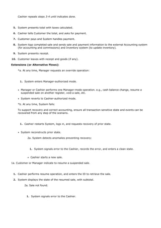


![6.9. What do the Sections Mean?
Preface Elements
Scope
The scope bounds the system (or systems) under design. Typically, a use case describes use of one software (or
hardware plus software) system; in this case it is known as a system use case. At a broader scope, use cases
can also describe how a business is used by its customers and partners. Such an enterprise-level process
description is called a business use case and is a good example of the wide applicability of use cases, but they
aren't covered in this introductory book.
Level
In Cockburn's system, use cases are classified as at the user-goal level or the subfunction level, among others.
A user-goal level use case is the common kind that describe the scenarios to fulfill the goals of a primary actor
to get work done; it roughly corresponds to an elementary business process (EBP) in business process
engineering. A subfunction-level use case describes substeps required to support a user goal, and is usually
created to factor out duplicate substeps shared by several regular use cases (to avoid duplicating common
text); an example is the subfunction use case Pay by Credit, which could be shared by many regular use cases.
EBP p. 88
see the use case "include" relationship for more on subfunction use cases p. 494
Primary Actor
The principal actor that calls upon system services to fulfill a goal.
Stakeholders and Interests ListImportant!
This list is more important and practical than may appear at first glance. It suggests and bounds what the
system must do. To quote:
The [system] operates a contract between stakeholders, with the use cases detailing the behavioral parts
of that contract…The use case, as the contract for behavior, captures all and only the behaviors related to
satisfying the stakeholders' interests [Cockburn01].
This answers the question: What should be in the use case? The answer is: That which satisfies all the
stakeholders' interests. In addition, by starting with the stakeholders and their interests before writing the
remainder of the use case, we have a method to remind us what the more detailed responsibilities of the system](https://image.slidesharecdn.com/softwaredevleopment-100607174022-phpapp01/85/Software-Development-126-320.jpg)
![should be. For example, would I have identified a responsibility for salesperson commission handling if I had not
first listed the salesperson stakeholder and their interests? Hopefully eventually, but perhaps I would have
missed it during the first analysis session. The stakeholder interest viewpoint provides a thorough and
methodical procedure for discovering and recording all the required behaviors.
Stakeholders and Interests:
- Cashier: Wants accurate, fast entry and no payment errors, as cash drawer shortages are deducted
from his/her salary.
- Salesperson: Wants sales commissions updated.
-…
Preconditions and Success Guarantees (Postconditions)
First, don't bother with a precondition or success guarantee unless you are stating something non-obvious and
noteworthy, to help the reader gain insight. Don't add useless noise to requirements documents.
Preconditions state what must always be true before a scenario is begun in the use case. Preconditions are not
tested within the use case; rather, they are conditions that are assumed to be true. Typically, a precondition
implies a scenario of another use case, such as logging in, that has successfully completed. Note that there are
conditions that must be true, but are not worth writing, such as "the system has power." Preconditions
communicate noteworthy assumptions that the writer thinks readers should be alerted to.
Success guarantees (or postconditions) state what must be true on successful completion of the use
caseeither the main success scenario or some alternate path. The guarantee should meet the needs of all
stakeholders.
Preconditions: Cashier is identified and authenticated.
Success Guarantee (Postconditions): Sale is saved. Tax is correctly calculated. Accounting and Inventory
are updated. Commissions recorded. Receipt is generated.
Main Success Scenario and Steps (or Basic Flow)
This has also been called the "happy path" scenario, or the more prosaic "Basic Flow" or "Typical Flow." It
describes a typical success path that satisfies the interests of the stakeholders. Note that it often does not
include any conditions or branching. Although not wrong or illegal, it is arguably more comprehensible and
extendible to be very consistent and defer all conditional handling to the Extensions section.
Guideline
Defer all conditional and branching statements to the Extensions section.
The scenario records the steps, of which there are three kinds:
1. An interaction between actors.[3]
[3]Note that the system under discussion itself should be considered an actor when it plays an actor role collaborating
with other systems.
2.
3.](https://image.slidesharecdn.com/softwaredevleopment-100607174022-phpapp01/85/Software-Development-127-320.jpg)


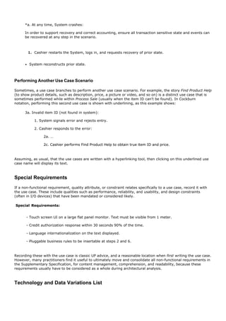


![6.10. Notation: Are There Other Formats? A Two-Column
Variation
Some prefer the two-column or conversational format, which emphasizes the interaction between the actors and
the system. It was first proposed by Rebecca Wirfs-Brock in [Wirfs-Brock93], and is also promoted by
Constantine and Lockwood to aid usability analysis and engineering [CL99]. Here is the same content using the
two-column format:
Use Case UC1: Process Sale
Primary Actor: …
… as before …
Main Success Scenario:
Actor Action (or Intention) System Responsibility
1.Customer arrives at a POS checkout with goods
and/or services to purchase.
2.Cashier starts a new sale.
3.Cashier enters item identifier. 4.Records each sale line item and presents item
description and running total.
Cashier repeats steps 3-4 until indicates done. 5.Presents total with taxes calculated.
6.Cashier tells Customer the total, and asks for
payment.
7.Customer pays. 8.Handles payment.
9.Logs the completed sale and sends information to the
external accounting (for all accounting and commissions)
and inventory systems (to update inventory). System
presents receipt.
… …
The Best Format?
There isn't one best format; some prefer the one-column style, some the two-column. Sections may be added
and removed; heading names may change. None of this is particularly important; the key thing is to write the
details of the main success scenario and its extensions, in some form. [Cockburn01] summarizes many usable
formats.](https://image.slidesharecdn.com/softwaredevleopment-100607174022-phpapp01/85/Software-Development-133-320.jpg)

![6.11. Guideline: Write in an Essential UI-Free Style
New and Improved! The Case for Fingerprinting
During a requirements workshop, the cashier may say one of his goals is to "log in." The cashier was probably
thinking of a GUI, dialog box, user ID, and password. This is a mechanism to achieve a goal, rather than the
goal itself. By investigating up the goal hierarchy ("What is the goal of that goal?"), the system analyst arrives
at a mechanism-independent goal: "identify myself and get authenticated," or an even higher goal: "prevent
theft …".
This root-goal discovery process can open up the vision to new and improved solutions. For example, keyboards
and mice with biometric readers, usually for a fingerprint, are now common and inexpensive. If the goal is
"identification and authentication" why not make it easy and fast using a biometric reader on the keyboard? But
properly answering that question involves some usability analysis work as well. Are their fingers covered in
grease? Do they have fingers?
Essential Style Writing
This idea has been summarized in various use case guidelines as "keep the user interface out; focus on intent"
[Cockburn01]. Its motivation and notation has been more fully explored by Larry Constantine in the context of
creating better user interfaces (UIs) and doing usability engineering [Constantine94, CL99]. Constantine calls
the writing style essential when it avoids UI details and focuses on the real user intent.[4]
[4] The term comes from "essential models" in Essential Systems Analysis [MP84].
In an essential writing style, the narrative is expressed at the level of the user's intentions and system's
responsibilities rather than their concrete actions. They remain free of technology and mechanism details,
especially those related to the UI.
Guideline
Write use cases in an essential style; keep the user interface out and focus on actor intent.
All of the previous example use cases in this chapter, such as Process Sale, were written aiming towards an
essential style.
Contrasting Examples
Essential Style
Assume that the Manage Users use case requires identification and authentication:](https://image.slidesharecdn.com/softwaredevleopment-100607174022-phpapp01/85/Software-Development-135-320.jpg)


![Why Ask About Actor Goals Rather Than Use Cases?
Actors have goals and use applications to help satisfy them. The viewpoint of use case modeling is to find these
actors and their goals, and create solutions that produce a result of value. This is slight shift in emphasis for the
use case modeler. Rather than asking "What are the tasks?", one starts by asking: "Who uses the system and
what are their goals?" In fact, the name of a use case for a user goal should reflect its name, to emphasize this
viewpointGoal: capture or process a sale; use case: Process Sale.
Thus, here is a key idea regarding investigating requirements and use cases:
Imagine we are together in a requirements workshop. We could ask either:
"What do you do?" (roughly a task-oriented question) or,
"What are your goals whose results have measurable value?"
Prefer the second question.
Answers to the first question are more likely to reflect current solutions and procedures, and the complications
associated with them.
Answers to the second question, especially combined with an investigation to move higher up the goal hierarchy
("what is the root goal?") open up the vision for new and improved solutions, focus on adding business value,
and get to the heart of what the stakeholders want from the system.
Is the Cashier or Customer the Primary Actor?
Why is the cashier, and not the customer, a primary actor in the use case Process Sale?
The answer depends on the system boundary of the system under design, and who we are primarily designing
the system for, as illustrated in Figure 6.2. If the enterprise or checkout service is viewed as an aggregate
system, the customer is a primary actor, with the goal of getting goods or services and leaving. However, from
the viewpoint of just the POS system (which is the choice of system boundary for this case study), the system
services the goal of a trained cashier (and the store) to process the customer's sale. This assumes a traditional
checkout environment with a cashier, although there are an increasing number of self-checkout POS systems in
operation for direct use by customers.
Figure 6.2. Primary actors and goals at different system boundaries.
[View full size image]](https://image.slidesharecdn.com/softwaredevleopment-100607174022-phpapp01/85/Software-Development-142-320.jpg)


![6.16. Guideline: What Tests Can Help Find Useful Use Cases?
Which of these is a valid use case?
Negotiate a Supplier Contract
Handle Returns
Log In
Move Piece on Game Board
An argument can be made that all of these are use cases at different levels, depending on the system boundary,
actors, and goals.
But rather than asking in general, "What is a valid use case?", a more practical question is: "What is a useful
level to express use cases for application requirements analysis?" There are several rules of thumb, including:
The Boss Test
The EBP Test
The Size Test
The Boss Test
Your boss asks, "What have you been doing all day?" You reply: "Logging in!" Is your boss happy?
If not, the use case fails the Boss Test, which implies it is not strongly related to achieving results of measurable
value. It may be a use case at some low goal level, but not the desirable level of focus for requirements
analysis.
That doesn't mean to always ignore boss-test-failing use cases. User authentication may fail the boss test, but
may be important and difficult.
The EBP Test
An Elementary Business Process (EBP) is a term from the business process engineering field,[5] defined as:
[5] EBP is similar to the term user task in usability engineering, although the meaning is less strict in that domain.
A task performed by one person in one place at one time, in response to a business event, which adds
measurable business value and leaves the data in a consistent state, e.g., Approve Credit or Price Order
[original source lost].
Focus on use cases that reflect EBPs.
The EBP Test is similar to the Boss Test, especially in terms of the measurable business value qualification.](https://image.slidesharecdn.com/softwaredevleopment-100607174022-phpapp01/85/Software-Development-145-320.jpg)


![6.17. Applying UML: Use Case Diagrams
The UML provides use case diagram notation to illustrate the names of use cases and actors, and the
relationships between them (see Figure 6.3).[6]
[6] "Cash In" is the act of a cashier arriving with a drawer insert with cash, logging in, and recording the cash amount in the drawer insert.
Figure 6.3. Partial use case context diagram.
[View full size image]
Use case diagrams and use case relationships are secondary in use case work. Use cases are text
documents. Doing use case work means to write text.
A common sign of a novice (or academic) use case modeler is a preoccupation with use case diagrams and use
case relationships, rather than writing text. World-class use case experts such as Fowler and Cockburn, among
others, downplay use case diagrams and use case relationships, and instead focus on writing. With that as a
caveat, a simple use case diagram provides a succinct visual context diagram for the system, illustrating the
external actors and how they use the system.](https://image.slidesharecdn.com/softwaredevleopment-100607174022-phpapp01/85/Software-Development-148-320.jpg)
![Guideline
Draw a simple use case diagram in conjunction with an actor-goal list.
A use case diagram is an excellent picture of the system context; it makes a good context diagram, that is,
showing the boundary of a system, what lies outside of it, and how it gets used. It serves as a communication
tool that summarizes the behavior of a system and its actors. A sample partial use case context diagram for the
NextGen system is shown in Figure 6.3.
Guideline: Diagramming
Figure 6.4 offers diagram advice. Notice the actor box with the symbol «actor». This style is used for UML
keywords and stereotypes, and includes guillemet symbolsspecial single-character brackets («actor», not
<<actor>>) most widely known by their use in French typography to indicate a quote.
Figure 6.4. Notation suggestions.
To clarify, some prefer to highlight external computer system actors with an alternate notation, as illustrated in
Figure 6.5.
Figure 6.5. Alternate actor notation.
[View full size image]](https://image.slidesharecdn.com/softwaredevleopment-100607174022-phpapp01/85/Software-Development-149-320.jpg)


![6.19. Motivation: Other Benefits of Use Cases? Requirements in
Context
A motivation for use cases is focusing on who the key actors are, their goals, and common tasks. Plus, in
essence, use cases are a simple, widely-understood form (a story or scenario form).
motivation p. 64
Another motivation is to replace detailed, low-level function lists (which were common in 1970s traditional
requirements methods) with use cases. These lists tended to look as follows:
ID Feature
FEAT1.9 The system shall accept entry of item identifiers.
… …
FEAT2.4 The system shall log credit payments to the accounts
receivable system.
As implied by the title of the book Uses Cases: Requirements in Context [GK00], use cases organize a set of
requirements in the context of the typical scenarios of using a system. That's a good thingit improves cohesion
and comprehension to consider and group requirements by the common thread of user-oriented scenarios (i.e.,
use cases). In a recent air traffic control system project: the requirements were originally written in the old-
fashioned function list format, filling volumes of incomprehensible, unrelated specifications. A new leadership
team analyzed and reorganized the massive requirements primarily by use cases. This provided a unifying and
understandable way to pull the requirements togetherinto stories of requirements in context of use.
To reiterate, however, use cases are not the only necessary requirements artifact. Non-functional requirements,
report layouts, domain rules, and other hard-to-place elements are better captured in the UP Supplementary
Specification.
Supplementary Specification p. 104
High-Level System Feature Lists Are Acceptable
Vision p. 109
Although detailed function lists are undesirable, a terse, high-level feature list, called system features, added to
a Vision document can usefully summarize system functionality. In contrast to 50 pages of low-level features, a](https://image.slidesharecdn.com/softwaredevleopment-100607174022-phpapp01/85/Software-Development-152-320.jpg)


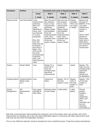
![of the core of a system starts quickly, long before all the requirements are known.
Observe that near the end of the first iteration of elaboration, there is a second requirements workshop, during
which perhaps 30% of the use cases are written in detail. This staggered requirements analysis benefits from
the feedback of having built a little of the core software. The feedback includes user evaluation, testing, and
improved "knowing what we don't know." The act of building software rapidly surfaces assumptions and
questions that need clarification.
In the UP, use case writing is encouraged in a requirements workshop. Figure 6.7 offers suggestions on the time
and space for doing this work.
Figure 6.7. Process and setting context for writing use cases.
[View full size image]
When Should Various UP Artifact (Including Use Cases) be Created?
Table 6.2 illustrates some UP artifacts, and an example of their start and refinement schedule. The Use-Case
Model is started in inception, with perhaps only 10% of the architecturally significant use cases written in any
detail. The majority are incrementally written over the iterations of the elaboration phase, so that by the end of
elaboration, a large body of detailed use cases and other requirements (in the Supplementary Specification) are
written, providing a realistic basis for estimation through to the end of the project.
Table 6.2. Sample UP artifacts and timing. s - start; r - refine](https://image.slidesharecdn.com/softwaredevleopment-100607174022-phpapp01/85/Software-Development-158-320.jpg)


![6.22. History
The idea of use cases to describe functional requirements was introduced in 1986 by Ivar Jacobson
[Jacobson92], a main contributor to the UML and UP. Jacobson's use case idea was seminal and widely
appreciated. Although many have made contributions to the subject, arguably the most influential and coherent
next step in defining what use cases are and how to write them came from Alistair Cockburn (who was trained
by Jacobson), based on his earlier work and writings stemming from 1992 onwards [e.g., Cockburn01].](https://image.slidesharecdn.com/softwaredevleopment-100607174022-phpapp01/85/Software-Development-161-320.jpg)
![6.23. Recommended Resources
The most popular use-case guide, translated into several languages, is Writing Effective Use Cases
[Cockburn01].[7] This has emerged with good reason as the most widely read and followed use-case book and is
therefore recommended as a primary reference. This introductory chapter is consequently based on and
consistent with its content.
[7] Note that Cockburn rhymes with slow burn.
Patterns for Effective Use Cases by Adolph and Bramble in some ways picks up where Writing leaves off,
covering many useful tipsin pattern formatrelated to the process of creating excellent use cases (team
organization, methodology, editing), and how to better structure and write them (patterns for judging and
improving their content and organization).
Use cases are usually best written with a partner during a requirements workshop. An excellent guide to the art
of running a workshop is Requirements by Collaboration: Workshops for Defining Needs by Ellen Gottesdiener.
Use Case Modeling by Bittner and Spence is another quality resource by two experienced modelers who also
understand iterative and evolutionary development and the RUP, and present use case analysis in that context.
"Structuring Use Cases with Goals" [Cockburn97] is the most widely cited paper on use cases, available online
at alistair.cockburn.us.
Use Cases: Requirements in Context by Kulak and Guiney is also worthwhile. It emphasizes the important
viewpointas the title statesthat use cases are not just another requirements artifact, but are the central vehicle
that drives requirements work.](https://image.slidesharecdn.com/softwaredevleopment-100607174022-phpapp01/85/Software-Development-162-320.jpg)
![Introduction
There are a few other important UP requirement artifacts in addition to use cases; this chapter introduces them.
If you want to skip this chapterwhich deals with the secondary topic of requirements rather than OOA/Dno
problem. Jump to the classic OOA subject of domain modeling on p. 131, after first reading the summary of
iteration-1 requirements starting on p. 124.
So why include this chapter if it isn't central to learning OOA/D? Because it gives cohesion to the case studies
and offers a more complete requirements example.
[View full size image]](https://image.slidesharecdn.com/softwaredevleopment-100607174022-phpapp01/85/Software-Development-164-320.jpg)

![7.1. How Complete are these Examples?
The book's prime goal is basic OOA/D, not the secondary POS requirement details discussed in this chapter. So
rather than show exhaustive requirements examples,[1] the chapter presents partial examples.
[1] Scope creep is not only a problem in requirements, but in writing about requirements!
Some sections are briefly shown to make connections between prior and future work, highlight noteworthy
issues, provide a feel for the contents, and move forward quickly.](https://image.slidesharecdn.com/softwaredevleopment-100607174022-phpapp01/85/Software-Development-166-320.jpg)
![7.2. Guideline: Should We Analyze These Thoroughly During
Inception?
No. The UP is an iterative and evolutionary method, which means that production-quality programming and
testing should happen very early, long before most requirements have been fully analyzed or recorded.
Feedback from early programming and tests evolve the requirements.
However, research shows that is useful to have a high-level "top ten" list of coarse-grained requirements near
the start. It is also useful to spend non-trivial early time understanding the non-functional requirements (such
as performance or reliability), as these have a significant impact on architectural choices.
Reliable Specifications: An Oxymoron?
The following written requirement examples could promote the illusion that the real requirements are
understood and well-defined, and can (early on) be used to reliably estimate and plan the project. This illusion is
more strong for non-software developers; programmers know from painful experience how unreliable it is. As
mentioned, case studies (for example, [Thomas01] and [Larman03]) now show it is a misunderstanding to
believe that early detailed requirements are useful or reliable on software projects. In fact, quite the opposite,
as almost 50% of early waterfall-specified features are never used in a system.
What really matters is quickly building software that passes the acceptance tests defined by the users, and that
meets their true goalswhich are often not discovered until users are evaluating or working with the software.
Writing a Vision and Supplementary Specification is worthwhile as an exercise in clarifying a first approximation
of what is wanted, the motivation for the product, and as a repository for the big ideas. But they are notnor is
any requirements artifacta reliable specification. Only writing code, testing it, getting feedback, ongoing close
collaboration with users and customers, and adapting, truly hit the mark.
This is not a call to abandon analysis and thinking, and just rush to code, but a suggestion to treat written
requirements lightly, start programming early, and continuallyideally, dailyengage users and tests for feedback.](https://image.slidesharecdn.com/softwaredevleopment-100607174022-phpapp01/85/Software-Development-167-320.jpg)
![7.3. Guideline: Should These Artifacts be at the Project
Website?
Definitely. Since this is a book, these examples and the use cases have a static and perhaps paper-oriented feel.
Nevertheless, these should usually be digital artifacts recorded only online at the project website. And instead of
being plain static documents, they may be hyperlinked, or recorded in tools other than a word processor or
spreadsheet. For example, many of these could be stored in a Wiki Web.[2]
[2] For an introduction to Wikis, see http://en.wikipedia.org/wiki/WikiWiki.](https://image.slidesharecdn.com/softwaredevleopment-100607174022-phpapp01/85/Software-Development-168-320.jpg)


![7.5. Commentary: Supplementary Specification
The Supplementary Specification captures other requirements, information, and constraints not easily
captured in the use cases or Glossary, including system-wide "URPS+" (usability, reliability, performance,
supportability, and more) quality attributes or requirements.
Note that non-functional requirements specific to a use case can (and probably should) be first briefly written
within the use case, in the Special Requirements section while you are thinking through the use case. But, after
that informal step, these should then be moved to the Supplementary Specification, to keep all non-functional
requirements in one place, and not duplicated.
Elements of the Supplementary Specification include:
FURPS+ requirementsfunctionality, usability, reliability, performance, and supportability
reports
hardware and software constraints (operating and networking systems, …)
development constraints (for example, process or development tools)
other design and implementation constraints
internationalization concerns (units, languages)
documentation (user, installation, administration) and help
licensing and other legal concerns
packaging
standards (technical, safety, quality)
physical environment concerns (for example, heat or vibration)
operational concerns (for example, how do errors get handled, or how often should backups be done?)
application-specific domain rules
information in domains of interest (for example, what is the entire cycle of credit payment handling?)
Quality Attributes
Some requirements are called quality attributes [BCK98] (or "-ilities") of a system. These include usability,
reliability, and so forth. Note that these are qualities of the system, not of the attributes themselves, which are
not necessarily of high quality. For example, the quality of supportability might deliberately be chosen to be low
if the product is not intended to serve a long-term purpose.
When we put on our "architect hat," the system-wide quality attributes (and thus the Supplementary
Specification where one records them) are especially interesting becauseas will be introduced in Chapter
33architectural analysis and design are largely concerned with the identification and resolution of the quality
attributes in the context of the functional requirements.
For example, suppose one of the quality attributes is that the NextGen system must be quite fault-tolerant
when remote services fail. From an architectural viewpoint, that will have an overarching influence on large-
scale design decisions.](https://image.slidesharecdn.com/softwaredevleopment-100607174022-phpapp01/85/Software-Development-173-320.jpg)


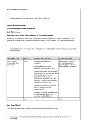
![Cashier: process sales, handle returns, cash in, cash out
System administrator: manage users, manage security, manage system tables
Manager: start up, shut down
Sales activity system: analyze sales data
…
User Environment…
Product Overview
Product Perspective
The NextGen POS will usually reside in stores; if mobile terminals are used, they will be in close
proximity to the store network, either inside or close outside. It will provide services to users, and
collaborate with other systems, as indicated in Figure Vision-1.
Figure vision- 1. NextGen POS system context diagram
[View full size image]
Summarized from the use case diagram.
Context diagrams come in different formats with varying detail, but all show the major
external actors related to a system.
Summary of Benefits
Supporting Feature Stakeholder Benefit
Functionally, the system will provide all the Automated, fast point-of-sale services.
common services a sales organization requires,
including sales capture, payment authorization,
return handling, and so forth.](https://image.slidesharecdn.com/softwaredevleopment-100607174022-phpapp01/85/Software-Development-177-320.jpg)


![7.7. Commentary: Vision
When someone joins the project, it is useful to be able to say, "Welcome! Please go read the 7-page Vision at
the project website." It is also useful to have an executive summary that briefly describes the project, as a
context for the major players to establish a common vision of the project.
The Vision should not be long, nor should it attempt to describe firm requirements in detail. And it should
summarize some of the information in the Use-Case Model and Supplementary Specification.
The Key High-Level Goals and Problems of the Stakeholders
This section summarizes the goals and problems at a high leveloften higher than specific use casesand reveals
important non-functional and quality goals that may belong to one use case or span many, such as:
We need fault-tolerant sales processing.
We need the ability to customize the business rules.
Guideline: What are Some Facilitation Methods?
It is especially during activities such as high-level problem definition and goal identification that creative,
investigative group work occurs. Here are some useful group facilitation techniques to discover root problems
and goals, and support idea generation and prioritization: mind mapping, product vision box creation, fishbone
diagrams, pareto diagrams, brainstorming, multi-voting, dot voting, nominal group process, brainwriting, and
affinity grouping. Check them out on the Web. I prefer to apply several of these during the same workshop, to
discover common problems and requirements from different angles.
Summary of System Features
Simply listing the use case names is not sufficient in the Vision to grasp the major features. Why?
Too detailed or low-level. People want a short summary of the big ideas. There could be 30 or 50 use
cases.
The use case name can hide interesting major features stakeholders really want to know about. For
example, suppose that the description of automated payment authorization functionality is embedded in
the Process Sale use case. A reader of a list of use case names can't tell if the system will do payment
authorization.
Some noteworthy features span or are orthogonal to the use cases. For example, during the first NextGen
requirements workshop, someone might say "The system should be able to interact with existing third-
party accounting, inventory, and tax calculation systems."
Therefore, an alternative, complementary way to express system functions is with features, or more specifically
in this context, system features, which are high-level, terse statements summarizing system functions. More
formally, in the UP, a system feature is "an externally observable service provided by the system which
directly fulfills a stakeholder need" [Kruchten00].](https://image.slidesharecdn.com/softwaredevleopment-100607174022-phpapp01/85/Software-Development-180-320.jpg)


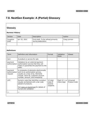


![7.11. Commentary: Domain Rules
Domain rules [Ross97, GK00] dictate how a domain or business may operate. They are not requirements of
any one application, although an application's requirements are often influenced by domain rules. Company
policies, physical laws (such as how oil flows underground), and government laws are common domain rules.
They are commonly called business rules, which is the most common type, but that term is poor, as many
software applications are for non-business problems, such as weather simulation or military logistics. A weather
simulation has "domain rules," related to physical laws and relationships, that influence the application
requirements.
It's useful to identify and record domain rules in a separate application-independent artifactwhat the UP calls the
Business Rules artifactso that this analysis can be shared and reused across the organization and across
projects, rather than buried within a project-specific document.
The rules can help clarify ambiguities in the use cases, which emphasize the flow of the story rather than the
details. For example, in the NextGen POS, if someone asks if the Process Sale use case should be written with
an alternative to allow credit payments without signature capture, there is a business rule (RULE1) that clarifies
whether this will not be allowed by any credit authorization company.](https://image.slidesharecdn.com/softwaredevleopment-100607174022-phpapp01/85/Software-Development-187-320.jpg)
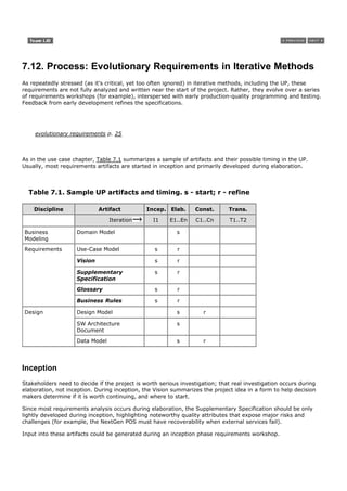

![7.13. Recommended Resources
Most books on software architecture include discussion of requirements analysis for quality attributes of the
application, since these quality requirements tend to strongly influence architectural design. One example is
Software Architecture in Practice [BCK98].
Business rules get an exhaustive treatment in The Business Rule Book [Ross97]. The book presents a broad,
deep, and thoroughly-considered theory of business rules, but the method is not well-connected to other
modern requirements techniques such as use cases, or to iterative development.
In the UP, Vision and Supplementary Specification work is a requirements discipline activity that could be
initiated during a requirements workshop, along with use case analysis. A good guide for running a workshop is
Requirements by Collaboration: Workshops for Defining Needs by Ellen Gottesdiener.
The RUP online product contains templates for the artifacts discussed in this chapter.
On the Web, templates for specifications are available from many sources, such as the ReadySET templates at
readyset.tigris.org.](https://image.slidesharecdn.com/softwaredevleopment-100607174022-phpapp01/85/Software-Development-190-320.jpg)
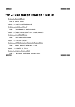

![Introduction
This chapter summarizes the iteration-1 requirements of the case studies, and then briefly discusses the process
ideas of the inception and elaboration phases. Reading the chosen requirements is important to understand
what's being tackled in the following chapters for this iteration; reading the remainder depends on your need or
interest in iterative process issues.
[View full size image]](https://image.slidesharecdn.com/softwaredevleopment-100607174022-phpapp01/85/Software-Development-193-320.jpg)


![Introduction
A domain model is the most importantand classicmodel in OO analysis.[1] It illustrates noteworthy concepts in a
domain. It can act as a source of inspiration for designing some software objects and will be an input to several
artifacts explored in the case studies. This chapter also shows the value of OOA/D knowledge over UML
notation; the basic notation is trivial, but there are subtle modeling guidelines for a useful modelexpertise can
take weeks or months. This chapter explores basic skills in creating domain models.
[1] Use cases are an important requirements analysis artifact, but are not object-oriented. They emphasize an activity view.
more advanced domain modeling p. 507
[View full size image]
As with all things in an agile modeling and UP spirit, a domain model is optional. UP artifact influence
emphasizing a domain model is shown in Figure 9.1. Bounded by the use case scenarios under development for
the current iteration, the domain model can be evolved to show related noteworthy concepts. The related use
case concepts and insight of experts will be input to its creation. The model can in turn influence operation
contracts, a glossary, and the Design Model, especially the software objects in the domain layer of the Design
Model.
Figure 9.1. Sample UP artifact influence.
[View full size image]](https://image.slidesharecdn.com/softwaredevleopment-100607174022-phpapp01/85/Software-Development-202-320.jpg)

![9.1. Example
Figure 9.2 shows a partial domain model drawn with UML class diagram notation. It illustrates that the
conceptual classes of Payment and Sale are significant in this domain, that a Payment is related to a Sale in a
way that is meaningful to note, and that a Sale has a date and time, information attributes we care about.
Figure 9.2. Partial domain modela visual dictionary.
[View full size image]
Applying the UML class diagram notation for a domain model yields a conceptual perspective model.
conceptual perspective p. 12
Identifying a rich set of conceptual classes is at the heart of OO analysis. If it is done with skill and short time
investment (say, no more than a few hours in each early iteration), it usually pays off during design, when it
supports better understanding and communication.](https://image.slidesharecdn.com/softwaredevleopment-100607174022-phpapp01/85/Software-Development-204-320.jpg)

![9.2. What is a Domain Model?
The quintessential object-oriented analysis step is the decomposition of a domain into noteworthy concepts or
objects.
A domain model is a visual representation of conceptual classes or real-situation objects in a domain [MO95,
Fowler96]. Domain models have also been called conceptual models (the term used in the first edition of this
book), domain object models, and analysis object models.[2]
[2]
They are also related to conceptual entity relationship models, which are capable of showing purely conceptual views of domains, but that have
been widely re-interpreted as data models for database design. Domain models are not data models.
Definition
In the UP, the term "Domain Model" means a representation of real-situation conceptual classes,
not of software objects. The term does not mean a set of diagrams describing software classes, the
domain layer of a software architecture, or software objects with responsibilities.
The UP defines the Domain Model[3] as one of the artifacts that may be created in the Business Modeling
discipline. More precisely, the UP Domain Model is a specialization of the UP Business Object Model (BOM)
"focusing on explaining 'things' and products important to a business domain" [RUP]. That is, a Domain Model
focuses on one domain, such as POS related things. The more broad BOM, not covered in this introductory text
and not something I encourage creating (because it can lead to too much up-front modeling), is an expanded,
often very large and difficult to create, multi-domain model that covers the entire business and all its sub-
domains.
[3]
Capitalization of "Domain Model" or terms is used to emphasize it as an official model name defined in the UP, versus the general well-known
concept of "domain models."
Applying UML notation, a domain model is illustrated with a set of class diagrams in which no operations
(method signatures) are defined. It provides a conceptual perspective. It may show:
domain objects or conceptual classes
associations between conceptual classes
attributes of conceptual classes
Definition: Why Call a Domain Model a "Visual Dictionary"?
Please reflect on Figure 9.2 for a moment. See how it visualizes and relates words or concepts in the domain. It
also shows an abstraction of the conceptual classes, because there are many other things one could
communicate about registers, sales, and so forth.
The information it illustrates (using UML notation) could alternatively have been expressed in plain text (in the
UP Glossary). But it's easy to understand the terms and especially their relationships in a visual language, since
our brains are good at understanding visual elements and line connections.
Therefore, the domain model is a visual dictionary of the noteworthy abstractions, domain vocabulary, and
information content of the domain.](https://image.slidesharecdn.com/softwaredevleopment-100607174022-phpapp01/85/Software-Development-206-320.jpg)
![Definition: Is a Domain Model a Picture of Software Business Objects?
A UP Domain Model, as shown in Figure 9.3, is a visualization of things in a real-situation domain of interest, not
of software objects such as Java or C# classes, or software objects with responsibilities (see Figure 9.4).
Therefore, the following elements are not suitable in a domain model:
Software artifacts, such as a window or a database, unless the domain being modeled is of software
concepts, such as a model of graphical user interfaces.
Responsibilities or methods.[4]
[4]
In object modeling, we usually speak of responsibilities related to software objects. And methods are purely a software concept. But, the
domain model describes real-situation concepts, not software objects. Considering object responsibilities during design work is very
important; it is just not part of this model.
Figure 9.3. A domain model shows real-situation conceptual classes, not software
classes.
Figure 9.4. A domain model does not show software artifacts or classes.
Definition: What are Two Traditional Meanings of "Domain Model"?
In the UP and thus this chapter, "Domain Model" is a conceptual perspective of objects in a real situation of the
world, not a software perspective. But the term is overloaded; it also has been used (especially in the Smalltalk
community where I did most of my early OO development work in the 1980s) to mean "the domain layer of
software objects." That is, the layer of software objects below the presentation or UI layer that is composed of
domain objectssoftware objects that represent things in the problem domain space with related "business
logic" or "domain logic" methods. For example, a Board software class with a getSquare method.](https://image.slidesharecdn.com/softwaredevleopment-100607174022-phpapp01/85/Software-Development-207-320.jpg)
![Which definition is correct? Well, all of them! The term has long established uses in different communities to
mean different things.
I've seen lots of confusion generated by people using the term in different ways, without explaining which
meaning they intend, and without recognizing that others may be using it differently.
In this book, I'll usually write domain layer to indicate the second software-oriented meaning of domain model,
as that's quite common.
Definition: What are Conceptual Classes?
The domain model illustrates conceptual classes or vocabulary in the domain. Informally, a conceptual class is
an idea, thing, or object. More formally, a conceptual class may be considered in terms of its symbol, intension,
and extension [MO95] (see Figure 9.5).
Symbol words or images representing a conceptual class.
Intension the definition of a conceptual class.
Extension the set of examples to which the conceptual class applies.
Figure 9.5. A conceptual class has a symbol, intension, and extension.
[View full size image]
For example, consider the conceptual class for the event of a purchase transaction. I may choose to name it by
the (English) symbol Sale. The intension of a Sale may state that it "represents the event of a purchase
transaction, and has a date and time." The extension of Sale is all the examples of sales; in other words, the set
of all sale instances in the universe.](https://image.slidesharecdn.com/softwaredevleopment-100607174022-phpapp01/85/Software-Development-208-320.jpg)
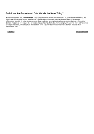
![9.3. Motivation: Why Create a Domain Model?
I'll share a story that I've experienced many times in OO consulting and coaching. In the early 1990s I was
working with a group developing a funeral services business system in Smalltalk, in Vancouver (you should see
the domain model!). Now, I knew almost nothing about this business, so one reason to create a domain model
was so that I could start to understand their key concepts and vocabulary.
We also wanted to create a domain layer of Smalltalk objects representing business objects and logic. So, we
spent perhaps one hour sketching a UML-ish (actually OMT-ish, whose notation inspired UML) domain model,
not worrying about software, but simply identifying the key terms. Then, those terms we sketched in the
domain model, such as Service (like flowers in the funeral room, or playing "You Can't Always Get What You
Want"), were also used as the names of key software classes in our domain layer implemented in Smalltalk.
domain layer p. 206
This similarity of naming between the domain model and the domain layer (a real "service" and a Smalltalk
Service) supported a lower gap between the software representation and our mental model of the domain.
Motivation: Lower Representational Gap with OO Modeling
This is a key idea in OO: Use software class names in the domain layer inspired from names in the domain
model, with objects having domain-familiar information and responsibilities. Figure 9.6 illustrates the idea. This
supports a low representational gap between our mental and software models. And that's not just a
philosophical nicetyit has a practical time-and-money impact. For example, here's a source-code payroll
program written in 1953:
1000010101000111101010101010001010101010101111010101 …
Figure 9.6. Lower representational gap with OO modeling.
[View full size image]](https://image.slidesharecdn.com/softwaredevleopment-100607174022-phpapp01/85/Software-Development-210-320.jpg)
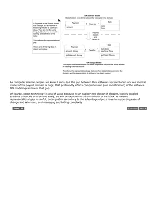


![Conceptual Class Category Examples
roles of people or organizations related to the transaction; Cashier, Customer, Store MonopolyPlayer
actors in the use case Passenger, Airline
Guideline: We usually need to know about the parties involved in
a transaction.
place of transaction; place of service Store
Airport, Plane, Seat
noteworthy events, often with a time or place we need to Sale, Payment MonopolyGame Flight
remember
physical objects Item, Register Board, Piece, Die Airplane
Guideline: This is especially relevant when creating device-control
software, or simulations.
descriptions of things ProductDescription
Guideline: See p. 147 for discussion. FlightDescription
catalogs ProductCatalog
Guideline: Descriptions are often in a catalog. FlightCatalog
containers of things (physical or information) Store, Bin Board Airplane
things in a container Item Square (in a Board) Passenger
other collaborating systems CreditAuthorizationSystem
AirTrafficControl
records of finance, work, contracts, legal matters Receipt, Ledger
MaintenanceLog
financial instruments Cash, Check, LineOfCredit
TicketCredit
schedules, manuals, documents that are regularly referred DailyPriceChangeList
to in order to perform work
RepairSchedule
Method 3: Finding Conceptual Classes with Noun Phrase Identification
Another useful technique (because of its simplicity) suggested in [Abbot83] is linguistic analysis: Identify the
nouns and noun phrases in textual descriptions of a domain, and consider them as candidate conceptual classes
or attributes.[5]
[5] Linguistic analysis has become more sophisticated; it also goes by the name natural language modeling. See [Moreno97] for example.
Guideline
Care must be applied with this method; a mechanical noun-to-class mapping isn't possible, and
words in natural languages are ambiguous.](https://image.slidesharecdn.com/softwaredevleopment-100607174022-phpapp01/85/Software-Development-214-320.jpg)


![9.10. Guideline: Think Like a Mapmaker; Use Domain Terms
The mapmaker strategy applies to both maps and domain models.
Guideline
Make a domain model in the spirit of how a cartographer or mapmaker works:
Use the existing names in the territory. For example, if developing a model for a library,
name the customer a "Borrower" or "Patron"the terms used by the library staff.
Exclude irrelevant or out-of-scope features. For example, in the Monopoly domain model for
iteration-1, cards (such as the "Get out of Jail Free" card) are not used, so don't show a Card
in the model this iteration.
Do not add things that are not there.
The principle is similar to the Use the Domain Vocabulary strategy [Coad95].](https://image.slidesharecdn.com/softwaredevleopment-100607174022-phpapp01/85/Software-Development-222-320.jpg)


![9.13. Guideline: When to Model with 'Description' Classes?
A description class contains information that describes something else. For example, a ProductDescription that
records the price, picture, and text description of an Item. This was first named the Item-Descriptor pattern in
[Coad92].
Motivation: Why Use 'Description' Classes?
The following discussion may at first seem related to a rare, highly specialized issue. However, it turns out that
the need for description classes is common in many domain models.
Assume the following:
An Item instance represents a physical item in a store; as such, it may even have a serial number.
An Item has a description, price, and itemID, which are not recorded anywhere else.
Everyone working in the store has amnesia.
Every time a real physical item is sold, a corresponding software instance of Item is deleted from "software
land."
With these assumptions, what happens in the following scenario?
There is strong demand for the popular new vegetarian burgerObjectBurger. The store sells out, implying that
all Item instances of ObjectBurgers are deleted from computer memory.
Now, here is one problem: If someone asks, "How much do ObjectBurgers cost?", no one can answer, because
the memory of their price was attached to inventoried instances, which were deleted as they were sold.
Here are some related problems: The model, if implemented in software similar to the domain model, has
duplicate data, is space-inefficient, and error-prone (due to replicated information) because the description,
price, and itemID are duplicated for every Item instance of the same product.
The preceding problem illustrates the need for objects that are descriptions (sometimes called specifications) of
other things. To solve the Item problem, what is needed is a ProductDescription class that records information
about items. A ProductDescription does not represent an Item, it represents a description of information about
items. See Figure 9.9.
Figure 9.9. Descriptions about other things. The * means a multiplicity of "many."
It indicates that one ProductDescription may describe many (*) Items.](https://image.slidesharecdn.com/softwaredevleopment-100607174022-phpapp01/85/Software-Development-225-320.jpg)


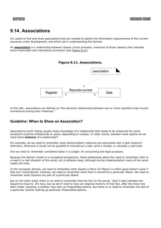


![Figure 9.14. Multiplicity values.
The multiplicity value communicates how many instances can be validly associated with another, at a particular
moment, rather than over a span of time. For example, it is possible that a used car could be repeatedly sold
back to used car dealers over time. But at any particular moment, the car is only Stocked-by one dealer. The
car is not Stocked-by many dealers at any particular moment. Similarly, in countries with monogamy laws, a
person can be Married-to only one other person at any particular moment, even though over a span of time,
that same person may be married to many persons.
The multiplicity value is dependent on our interest as a modeler and software developer, because it
communicates a domain constraint that will be (or could be) reflected in software. See Figure 9.15 for an
example and explanation.
Figure 9.15. Multiplicity is context dependent.
[View full size image]](https://image.slidesharecdn.com/softwaredevleopment-100607174022-phpapp01/85/Software-Development-232-320.jpg)
![Rumbaugh gives another example of Person and Company in the Works-for association [Rumbaugh91].
Indicating if a Person instance works for one or many Company instances is dependent on the context of the
model; the tax department is interested in many; a union probably only one. The choice usually depends on
why we are building the software.
Applying UML: Multiple Associations Between Two Classes
Two classes may have multiple associations between them in a UML class diagram; this is not uncommon. There
is no outstanding example in the POS or Monopoly case study, but an example from the domain of the airline is
the relationships between a Flight (or perhaps more precisely, a FlightLeg) and an Airport (see Figure 9.16); the
flying-to and flying-from associations are distinctly different relationships, which should be shown separately.
Figure 9.16. Multiple associations.
Guideline: How to Find Associations with a Common Associations List
Start the addition of associations by using the list in Table 9.2. It contains common categories that are worth
considering, especially for business information systems. Examples are drawn from the 1) POS, 2) Monopoly,
and 3) airline reservation domains.
Table 9.2. Common Associations List.
Category Examples
A is a transaction related to another CashPaymentSale
transaction B
CancellationReservation
A is a line item of a transaction B SalesLineItemSale
A is a product or service for a transaction ItemSalesLineItem (or Sale)
(or line item) B
FlightReservation
A is a role related to a transaction B CustomerPayment
PassengerTicket
A is a physical or logical part of B DrawerRegister
SquareBoard
SeatAirplane](https://image.slidesharecdn.com/softwaredevleopment-100607174022-phpapp01/85/Software-Development-233-320.jpg)

![9.15. Example: Associations in the Domain Models
Case Study: NextGen POS
The domain model in Figure 9.17 shows a set of conceptual classes and associations that are candidates for our
POS domain model. The associations are primarily derived from the "need-to-remember" criteria of this iteration
requirements, and the Common Association List. Reading the list and mapping the examples to the diagram
should explain the choices. For example:
Transactions related to another transaction Sale Paid-by CashPayment.
Line items of a transaction Sale Contains SalesLineItem.
Product for a transaction (or line item) SalesLineItem Records-sale-of Item.
Figure 9.17. NextGen POS partial domain model.
[View full size image]
Case Study: Monopoly
See Figure 9.18. Again, the associations are primarily derived from the "need-to-remember" criteria of this
iteration requirements, and the Common Association List. For example:](https://image.slidesharecdn.com/softwaredevleopment-100607174022-phpapp01/85/Software-Development-235-320.jpg)


![Some common examples are shown in Figure 9.20.
Figure 9.20. Attribute notation in UML.
[View full size image]
As a convention, most modelers will assume attributes have private visibility (-) unless shown otherwise, so I
don't usually draw an explicit visibility symbol.
{readOnly} is probably the most common property string for attributes.
Multiplicity can be used to indicate the optional presence of a value, or the number of objects that can fill a
(collection) attribute. For example, many domains require that a first and last name be known for a person, but
that a middle name is optional. The expression middleName : [0..1] indicates an optional value0 or 1 values are
present.
Guideline: Where to Record Attribute Requirements?
Notice that, subtly, middleName : [0..1] is a requirement or domain rule, embedded in the domain model.
Although this is just a conceptual-perspective domain model, it probably implies that the software perspective
should allow a missing value for middleName in the UI, the objects, and the database. Some modellers accept
leaving such specifications only in the domain model, but I find this error-prone and scattered, as people tend to
not look at the domain model in detail, or for requirements guidance. Nor do they usually maintain the domain
model.
Instead, I suggest placing all such attribute requirements in the UP Glossary, which serves as a data dictionary.
Perhaps I've spent an hour sketching a domain model with a domain expert; afterwards, I can spend 15
minutes looking through it and transferring implied attribute requirements into the Glossary.
Another alternative is to use a tool that integrates UML models with a data dictionary; then all attributes will
automatically show up as dictionary elements.
Derived Attributes
The total attribute in the Sale can be calculated or derived from the information in the SalesLineItems. When we
want to communicate that 1) this is a noteworthy attribute, but 2) it is derivable, we use the UML convention: a
/ symbol before the attribute name.
As another example, a cashier can receive a group of like items (for example, six tofu packages), enter the
itemID once, and then enter a quantity (for example, six). Consequently, an individual SalesLineItem can be
associated with more than one instance of an item.
The quantity that is entered by the cashier may be recorded as an attribute of the SalesLineItem (Figure 9.21).
However, the quantity can be calculated from the actual multiplicity value of the association, so it may be](https://image.slidesharecdn.com/softwaredevleopment-100607174022-phpapp01/85/Software-Development-238-320.jpg)
![characterized as a derived attributeone that may be derived from other information.
Figure 9.21. Recording the quantity of items sold in a line item.
[View full size image]
Guideline: What are Suitable Attribute Types?
Focus on Data Type Attributes in the Domain Model
Informally, most attribute types should be what are often thought of as "primitive" data types, such as numbers
and booleans. The type of an attribute should not normally be a complex domain concept, such as a Sale or
Airport.
For example, the currentRegister attribute in the Cashier class in Figure 9.22 is undesirable because its type is
meant to be a Register, which is not a simple data type (such as Number or String). The most useful way to
express that a Cashier uses a Register is with an association, not with an attribute.
Figure 9.22. Relate with associations, not attributes.](https://image.slidesharecdn.com/softwaredevleopment-100607174022-phpapp01/85/Software-Development-239-320.jpg)
![Guideline
The attributes in a domain model should preferably be data types. Very common data types
include: Boolean, Date (or DateTime), Number, Character, String (Text), Time.
Other common types include: Address, Color, Geometrics (Point, Rectangle), Phone Number, Social
Security Number, Universal Product Code (UPC), SKU, ZIP or postal codes, enumerated types
To repeat an earlier example, a common confusion is modeling a complex domain concept as an attribute. To
illustrate, a destination airport is not really a string; it is a complex thing that occupies many square kilometers
of space. Therefore, Flight should be related to Airport via an association, not with an attribute, as shown in
Figure 9.23.
Figure 9.23. Don't show complex concepts as attributes; use associations.
Guideline
Relate conceptual classes with an association, not with an attribute.
Data Types
As said, attributes in the domain model should generally be data types; informally these are "primitive" types
such as number, boolean, character, string, and enumerations (such as Size = {small, large}). More precisely,
this is a UML term that implies a set of values for which unique identity is not meaningful (in the context of our
model or system) [RJB99]. Said another way, equality tests are not based on identity, but instead on value.[6]
For example, it is not (usually) meaningful to distinguish between:
[6] In Java, for example, a value test is done with the equals method, and an identity test with the == operator.
Separate instances of the Integer 5.
Separate instances of the String 'cat'.
Separate instance of the Date "Nov. 13, 1990".
By contrast, it is meaningful to distinguish (by object identity) between two separate Person instances whose
names are both "Jill Smith" because the two instances can represent separate individuals with the same name.](https://image.slidesharecdn.com/softwaredevleopment-100607174022-phpapp01/85/Software-Development-240-320.jpg)

![Guideline
Represent what may initially be considered a number or string as a new data type class in the domain model
if:
It is composed of separate sections.
phone number, name of person
There are operations associated with it, such as parsing or validation.
social security number
It has other attributes.
promotional price could have a start (effective) date and end date
It is a quantity with a unit.
payment amount has a unit of currency
It is an abstraction of one or more types with some of these qualities.
item identifier in the sales domain is a generalization of types such as Universal Product Code (UPC)
and European Article Number (EAN)
Applying these guidelines to the POS domain model attributes yields the following analysis:
The item identifier is an abstraction of various common coding schemes, including UPC-A, UPC-E, and the
family of EAN schemes. These numeric coding schemes have subparts identifying the manufacturer,
product, country (for EAN), and a check-sum digit for validation. Therefore, there should be a data type
ItemID class, because it satisfies many of the guidelines above.
The price and amount attributes should be a data type Money class because they are quantities in a unit of
currency.
The address attribute should be a data type Address class because it has separate sections.
Applying UML: Where to Illustrate These Data Type Classes?
Should the ItemID class be shown as a separate class in a domain model? It depends on what you want to
emphasize in the diagram. Since ItemID is a data type (unique identity of instances is not used for equality
testing), it may be shown only in the attribute compartment of the class box, as shown in Figure 9.24. On the
other hand, if ItemID is a new type with its own attributes and associations, showing it as a conceptual class in
its own box may be informative. There is no correct answer; resolution depends on how the domain model is
being used as a tool of communication, and the significance of the concept in the domain.
Figure 9.24. Two ways to indicate a data type property of an object.
[View full size image]](https://image.slidesharecdn.com/softwaredevleopment-100607174022-phpapp01/85/Software-Development-242-320.jpg)
![Guideline: No Attributes Representing Foreign Keys
Attributes should not be used to relate conceptual classes in the domain model. The most common violation of
this principle is to add a kind of foreign key attribute, as is typically done in relational database designs, in
order to associate two types. For example, in Figure 9.25 the currentRegisterNumber attribute in the Cashier
class is undesirable because its purpose is to relate the Cashier to a Register object. The better way to express
that a Cashier uses a Register is with an association, not with a foreign key attribute. Once again, relate types
with an association, not with an attribute.
Figure 9.25. Do not use attributes as foreign keys.
[View full size image]
There are many ways to relate objectsforeign keys being oneand we will defer how to implement the relation
until design to avoid design creep.
Guideline: Modeling Quantities and Units
Most numeric quantities should not be represented as plain numbers. Consider price or weight. Saying "the price
was 13" or "the weight was 37" doesn't say much. Euros? Kilograms?
These are quantities with associated units, and it is common to require knowledge of the unit to support
conversions. The NextGen POS software is for an international market and needs to support prices in multiple
currencies. The domain model (and the software) should model quantities skillfully.
In the general case, the solution is to represent Quantity as a distinct class, with an associated Unit [Fowler96].
It is also common to show Quantity specializations. Money is a kind of quantity whose units are currencies.
Weight is a quantity with units such as kilograms or pounds. See Figure 9.26.
Figure 9.26. Modeling quantities.](https://image.slidesharecdn.com/softwaredevleopment-100607174022-phpapp01/85/Software-Development-243-320.jpg)
![[View full size image]](https://image.slidesharecdn.com/softwaredevleopment-100607174022-phpapp01/85/Software-Development-244-320.jpg)
![9.17. Example: Attributes in the Domain Models
Case Study: NextGen POS
See Figure 9.27. The attributes chosen reflect the information requirements for this iterationthe Process Sale
cash-only scenarios of this iteration. For example:
CashPayment amountTendered To determine if sufficient payment was provided, and to
calculate change, an amount (also known as "amount tendered") must be
captured.
Product-Description description To show the description on a display or receipt.
itemId To look up a ProductDescription.
price To calculate the sales total, and show the line item price.
Sale dateTime A receipt normally shows date and time of sale, and this is useful
for sales analysis.
SalesLineItem quantity To record the quantity entered, when there is more than one item in
a line item sale (for example, five packages of tofu).
Store address, name The receipt requires the name and address of the store.
Figure 9.27. NextGen POS partial domain model.
[View full size image]](https://image.slidesharecdn.com/softwaredevleopment-100607174022-phpapp01/85/Software-Development-245-320.jpg)
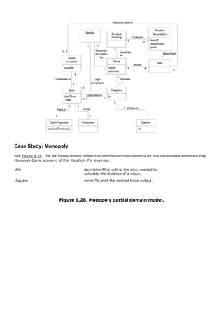


![elaboration phase p. 33
Inception
Domain models are not strongly motivated in inception, since inception's purpose is not to do a serious
investigation, but rather to decide if the project is worth deeper investigation in an elaboration phase.
Elaboration
The Domain Model is primarily created during elaboration iterations, when the need is highest to understand the
noteworthy concepts and map some to software classes during design work.
The UP Business Object Model vs. Domain Model
The UP Domain Model is an official variation of the less common UP Business Object Model (BOM). The UP
BOMnot to be confused with the many other definitions of a BOMis a kind of enterprise model that describes the
entire business. It may be used when doing business process engineering or reengineering, independent of any
one software application (such as the NextGen POS). To quote:
[The UP BOM] serves as an abstraction of how business workers and business entities need to be related
and how they need to collaborate in order to perform the business. [RUP]
The BOM is represented with several different diagrams (class, activity, and sequence) that illustrate how the
entire enterprise runs (or should run). It is most useful if doing enterprise-wide business process engineering,
but that is a less common activity than creating a single software application.
Consequently, the UP defines the Domain Model as the more commonly created subset artifact or specialization
of the BOM. To quote:
You can choose to develop an "incomplete" business object model, focusing on explaining "things" and
products important to a domain. […] This is often referred to as a domain model. [RUP]](https://image.slidesharecdn.com/softwaredevleopment-100607174022-phpapp01/85/Software-Development-250-320.jpg)
![9.20. Recommended Resources
Odell's Object-Oriented Methods: A Foundation provides a solid introduction to conceptual domain modeling.
Cook and Daniel's Designing Object Systems is also useful.
Fowler's Analysis Patterns offers worthwhile patterns in domain models and is definitely recommended. Another
good book that describes patterns in domain models is Hay's Data Model Patterns: Conventions of Thought.
Advice from data modeling experts who understand the distinction between pure conceptual models and
database schema models can be very useful for domain object modeling.
Java Modeling in Color with UML [CDL99] has much more relevant domain modeling advice than the title
suggests. The authors identify common patterns in related types and their associations; the color aspect is
really a visualization of the common categories of these types, such as descriptions (blue), roles (yellow), and
moment-intervals (pink). Color is used to aid in seeing the patterns.](https://image.slidesharecdn.com/softwaredevleopment-100607174022-phpapp01/85/Software-Development-251-320.jpg)
![Introduction
A system sequence diagram (SSD) is a fast and easily created artifact that illustrates input and output events
related to the systems under discussion. They are input to operation contracts andmost importantlyobject
design.
The UML contains notation in the form of sequence diagrams to illustrate events from external actors to a
system.
[View full size image]
UP artifact influence emphasizing system sequence diagrams is shown in Figure 10.1. The use case text and its
implied system events are input to SSD creation. The SSD operations (such as enterItem) can in turn be
analyzed in the operation contracts, detailed in the Glossary, andmost importantserve as the starting point for
designing collaborating objects.
Figure 10.1. Sample UP artifact influence.
[View full size image]](https://image.slidesharecdn.com/softwaredevleopment-100607174022-phpapp01/85/Software-Development-253-320.jpg)
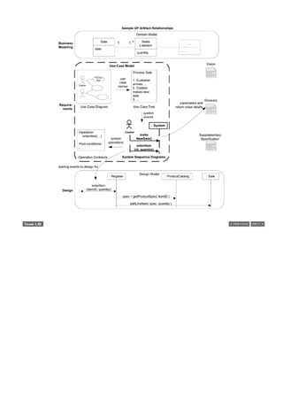
![10.1. Example: NextGen SSD
An SSD shows, for a particular course of events within a use case, the external actors that interact directly with
the system, the system (as a black box), and the system events that the actors generate (see Figure 10.2).
Time proceeds downward, and the ordering of events should follow their order in the scenario.
Figure 10.2. SSD for a Process Sale scenario.
[View full size image]
The Figure 10.2 example is for the main success scenario of a cash-only Process Sale scenario. It indicates that
the cashier generates makeNewSale, enterItem, endSale, and makePayment system events. These events are
implied or suggested by reading through the use case text.](https://image.slidesharecdn.com/softwaredevleopment-100607174022-phpapp01/85/Software-Development-255-320.jpg)


![10.5. What is the Relationship Between SSDs and Use Cases?
An SSD shows system events for one scenario of a use case, therefore it is generated from inspection of a use
case (see Figure 10.3).
Figure 10.3. SSDs are derived from use cases; they show one scenario.
[View full size image]
Applying UML: Should We Show Use Case Text in the SSD?
Not usually. If you name the SSD appropriately, you can indicate the use case; for example, Process Sale
Scenario.](https://image.slidesharecdn.com/softwaredevleopment-100607174022-phpapp01/85/Software-Development-259-320.jpg)


![10.11. History and Recommended Resources
Identifying a software system's public operations is a very old need, so variations of system interface diagrams
that illustrate the I/O events for a system treated as a black box have been in widespread use for many
decades. For example, in telecommunications they have been called call-flow diagrams. They were first
popularized in OO methods in the Fusion method [Coleman+94], which provided a detailed example of the
relationship of SSDs and system operations to other analysis and design artifacts.](https://image.slidesharecdn.com/softwaredevleopment-100607174022-phpapp01/85/Software-Development-265-320.jpg)

![Introduction
Use cases or system features are the main ways in the UP to describe system behavior, and are usually
sufficient. Sometimes a more detailed or precise description of system behavior has value. Operation contracts
use a pre- and post-condition form to describe detailed changes to objects in a domain model, as the result of a
system operation. A domain model is the most common OOA model, but operation contracts and state models
(introduced on p. 485) can also be useful OOA-related artifacts.
Operation contracts may be considered part of the UP Use-Case Model because they provide more analysis
detail on the effect of the system operations implied in the use cases.
[View full size image]
UP artifact influence emphasizing operation contracts is shown in Figure 11.1. The prime inputs to the contracts
are the system operations identified in SSDs (such as enterItem), the domain model, and domain insight from
experts. The contracts can in turn serve as input to the object design, as they describe changes that are likely
required in the software objects or database.
Figure 11.1. Sample UP artifact influence.
[View full size image]](https://image.slidesharecdn.com/softwaredevleopment-100607174022-phpapp01/85/Software-Development-267-320.jpg)


![11.3. Definition: What is a System Operation?
Operation contracts may be defined for system operationsoperations that the system as a black box
component offers in its public interface. System operations can be identified while sketching SSDs, as in Figure
11.2. To be more precise, the SSDs show system eventsevents or I/O messages relative to the system. Input
system events imply the system has system operations to handle the events, just as an OO message (a kind of
event or signal) is handled by an OO method (a kind of operation).
Figure 11.2. SSD. System operations handle input system events.
[View full size image]
The entire set of system operations, across all use cases, defines the public system interface, viewing the
system as a single component or class. In the UML, the system as a whole can be represented as one object of
a class named (for example) System.](https://image.slidesharecdn.com/softwaredevleopment-100607174022-phpapp01/85/Software-Development-271-320.jpg)


![11.11. Applying UML: Operations, Contracts, and the OCL
What's the relationship between contracts in this chapter and the UML?
The UML formally defines operations. To quote:
An operation is a specification of a transformation or query that an object may be called to execute.
[RJB99]
For example, the elements of an interface are operations, in UML terms. An operation is an abstraction, not an
implementation. By contrast, a method (in the UML) is an implementation of an operation. To quote:
[A method is] the implementation of an operation. It specifies the algorithm or procedure associated with
an operation. [OMG03a]
In the UML metamodel, an operation has a signature (name and parameters), and most importantly in this
context, is associated with a set of UML Constraint objects classified as preconditions and postconditions that
specify the semantics of the operation.
To summarize: The UML defines operation semantics via constraints, which are specifiable in the pre- and post-
condition style. Note that, as emphasized in this chapter, a UML operation specification can not show an
algorithm or solution, but only the state changes or effects of the operation.
In addition to using contracts to specify public operations of the entire System (that is, system operations),
contracts can be applied to operations at any level of granularity: the public operations (or interface) of a
subsystem, a component, an abstract class, and so forth. For example, operations can be defined for a single
software class such as a Stack. The coarse-grained operations discussed in this chapter belong to a System class
representing the overall system as a black box component, but in the UML operations can belong to any class or
interface, all with pre- and post-conditions.
Operation Contracts Expressed with the OCL
The pre- and post-condition format in this chapter is informal natural languageperfectly acceptable in the UML,
and desirable to be easily understood.
But also associated with the UML is a formal, rigorous language called the Object Constraint Language (OCL)
[WK99], which can be used to express constraints of UML operations.
Guideline
Unless there is a compelling practical reason to require people to learn and use the OCL, keep
things simple and use natural language. Although I'm sure there are realand usefulapplications,
I've never seen a project that used OCL, even though I visit many clients and projects.
The OCL defines an official format for specifying pre- and postconditions for operations, as demonstrated in this
fragment:
System::makeNewSale( )
pre : <statements in OCL>
post : …](https://image.slidesharecdn.com/softwaredevleopment-100607174022-phpapp01/85/Software-Development-282-320.jpg)

![11.12. Process: Operation Contracts Within the UP
A pre- and postcondition contract is a well-known style to specify an operation in the UML. In the UML,
operations exists at many levels, from System down to fine-grained classes, such as Sale. Operation contracts
for the System level are part of the Use-Case Model, although they were not formally highlighted in the original
RUP or UP documentation; their inclusion in this model was verified with the RUP authors.[1]
[1] Private communication.
Phases
Inception Contracts are not motivated during inceptionthey are too detailed.
Elaboration If used at all, most contracts will be written during elaboration, when most use cases are written.
Only write contracts for the most complex and subtle system operations.](https://image.slidesharecdn.com/softwaredevleopment-100607174022-phpapp01/85/Software-Development-284-320.jpg)
![11.13. History
Operation contracts come out of the formal specifications area in computer science, originally from the prolific
Tony Hoare. Hoare was working in industry in the mid-1960s to develop an ALGOL 60 compiler and read
Bertrand Russell's Introduction to Mathematical Philosophy, which introduced him to the idea of axiomatic
theory and assertions. He realized that computer programs could be expressed with assertions (pre- and post-
conditions) relative to the results that were expected at the launch and termination of a program. In 1968 he
joined academia, and his idea spread, along with other researchers' theories of formal specifications.
In 1974 at the IBM Lab in Vienna a PL/1 compiler was being developed, and the researchers desired an
unambiguous formal specification of the language. Out of this need VDLthe Vienna Definition Languagewas born
by Peter Lucas. VDL borrowed the pre- and post-condition assertion form earlier explored by Hoare and Russel.
VDL eventually evolved into the language used within the Vienna Definition Method (VDM), a method that
applied operation contract formal specifications and rigorous proof theory [BJ78].
In the 1980s, Bertrand Meyernot surprisingly yet another compiler writer (the OO language Eiffel)started to
promote the use of pre- and post-condition assertions as first-class elements within his Eiffel language, to be
applied to OOA/D. He contributed to a much wider awareness of formal specifications and operation contracts in
his popular book Object-Oriented Software Construction, in which he also proposed the approach as a method
called Design by Contract (DBC). In DBC, contracts are written for operations of fine-grained software class
operations, not specifically the public operations of the overall "system." In addition, DBC promotes an invariant
section, common in thorough contract specifications. Invariants define things that must not change state before
and after the operation has executed. Invariants have not been used in this chapter for the sake of simplicity.
In the early 1990s, Grady Booch briefly discussed applying contracts to object operations in his Booch Method.
Also, Derek Coleman and colleagues at HP Labs borrowed the operation contract idea and applied it to OOA and
domain modeling, making it part of the influential OOA/D Fusion method [Coleman+94].
Programming Language Support for Contracts
Some languages, such as Eiffel, have first-class support for invariants and pre- and post-conditions. Using
attributes, Javadoc tags, or pre-compilers, similar facilities can be provided in Java and C#, for example.](https://image.slidesharecdn.com/softwaredevleopment-100607174022-phpapp01/85/Software-Development-285-320.jpg)


![Introduction
So far, the case studies have emphasized analysis of the requirements and objects. If following the UP
guidelines, perhaps 10% of the requirements were investigated in inception, and a slightly deeper investigation
was started in this first iteration of elaboration. The following chapters are a shift in emphasis toward designing
a solution for this iteration in terms of collaborating software objects.
[View full size image]](https://image.slidesharecdn.com/softwaredevleopment-100607174022-phpapp01/85/Software-Development-288-320.jpg)


![Introduction
First, to set the expectation level: This is a very short introduction to the topic of logical architecture, a fairly
large topic. Learn more starting on p. 559.
Now that we have transitioned from analysis-oriented work to software design, let's start with the large-scale.
At this level, the design of a typical OO system is based on several architectural layers, such as a UI layer, an
application logic (or "domain") layer, and so forth. This chapter briefly explores a logical layered architecture
and related UML notation.
[View full size image]
UP artifact influence, emphasizing the logical architecture (LA), is shown in Figure 13.1. UML package diagrams
may illustrate the LA as part of the Design Modeland also be summarized as a view in the Software Architecture
Document. The prime input is the architectural forces captured in the Supplementary Specification. The LA
defines the packages within which software classes are defined.
Figure 13.1. Sample UP artifact influence.
[View full size image]](https://image.slidesharecdn.com/softwaredevleopment-100607174022-phpapp01/85/Software-Development-293-320.jpg)
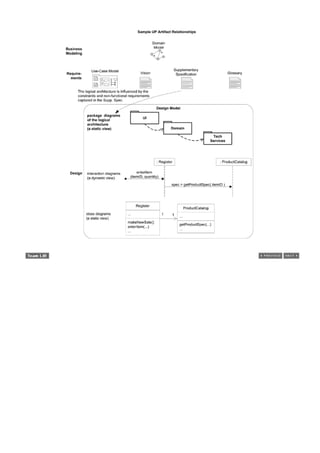


![13.4. What is Software Architecture?
I touched on the logical and deployment architectures, so now is a good time to introduce a definition for
software architecture. Here's one:
An architecture is the set of significant decisions about the organization of a software system, the selection
of the structural elements and their interfaces by which the system is composed, together with their
behavior as specified in the collaborations among those elements, the composition of these structural and
behavioral elements into progressively larger subsystems, and the architectural style that guides this
organizationthese elements and their interfaces, their collaborations, and their composition. [BRJ99]
Regardless of the definition (and there are many) the common theme in all software architecture definitions is
that it has to do with the large scalethe Big Ideas in the motivations, constraints, organization, patterns,
responsibilities, and connections of a system (or a system of systems).](https://image.slidesharecdn.com/softwaredevleopment-100607174022-phpapp01/85/Software-Development-298-320.jpg)
![13.5. Applying UML: Package Diagrams
UML package diagrams are often used to illustrate the logical architecture of a systemthe layers, subsystems,
packages (in the Java sense), etc. A layer can be modeled as a UML package; for example, the UI layer
modeled as a package named UI.
A UML package diagram provides a way to group elements. A UML package can group anything: classes, other
packages, use cases, and so on. Nesting packages is very common. A UML package is a more general concept
than simply a Java package or .NET namespace, though a UML package can represent thoseand more.
The package name may be placed on the tab if the package shows inner members, or on the main folder, if not.
It is common to want to show dependency (a coupling) between packages so that developers can see the large-
scale coupling in the system. The UML dependency line is used for this, a dashed arrowed line with the arrow
pointing towards the depended-on package.
A UML package represents a namespace so that, for example, a Date class may be defined in two packages. If
you need to provide fully-qualified names, the UML notation is, for example, java::util::Date in the case that
there was an outer package named "java" with a nested package named "util" with a Date class.
The UML provides alternate notations to illustrate outer and inner nested packages. Sometimes it is awkward to
draw an outer package box around inner packages. Alternatives are shown in Figure 13.3.
Figure 13.3. Alternate UML approaches to show package nesting, using embedded
packages, UML fully-qualified names, and the circle-cross symbol.
[View full size image]
UML Tools: Reverse-engineer Package Diagrams from Code
During early development, we may sketch a UML package diagram and then organize our code according to
these package sketches. Over time, the code base grows and we spend more time programming and less on
modeling or UML diagrams. At that point, a great use for a UML CASE tool is to reverse-engineer the source
code and generate a package diagram automatically.](https://image.slidesharecdn.com/softwaredevleopment-100607174022-phpapp01/85/Software-Development-299-320.jpg)

![13.6. Guideline: Design with Layers
The essential ideas of using layers [BMRSS96] are simple:
Organize the large-scale logical structure of a system into discrete layers of distinct, related
responsibilities, with a clean, cohesive separation of concerns such that the "lower" layers are low-level and
general services, and the higher layers are more application specific.
Collaboration and coupling is from higher to lower layers; lower-to-higher layer coupling is avoided.
Some more design issues are covered later, starting on p. 559. The idea is described as the Layers pattern in
[BMRSS96] and produces a layered architecture. It has been applied and written about so often as a pattern
that the Pattern Almanac 2000 [Rising00] lists over 100 patterns that are variants of or related to the Layers
pattern.
Using layers helps address several problems:
Source code changes are rippling throughout the systemmany parts of the systems are highly coupled.
Application logic is intertwined with the user interface, so it cannot be reused with a different interface or
distributed to another processing node.
Potentially general technical services or business logic is intertwined with more application-specific logic, so
it cannot be reused, distributed to another node, or easily replaced with a different implementation.
There is high coupling across different areas of concern. It is thus difficult to divide the work along clear
boundaries for different developers.
The purpose and number of layers varies across applications and application domains (information systems,
operating systems, and so forth). Applied to information systems, typical layers are illustrated and explained in
Figure 13.4.
Figure 13.4. Common layers in an information system logical architecture.[1]
[View full size image]](https://image.slidesharecdn.com/softwaredevleopment-100607174022-phpapp01/85/Software-Development-301-320.jpg)
![[1]
The width of the package is used to communicate range of applicability in this diagram, but this is not a general UML practice. AKA means Also
known As.
The Application layer in Figure 13.4 is discussed on p. 567.
Benefits of Using Layers
In general, there is a separation of concerns, a separation of high from low-level services, and of
application-specific from general services. This reduces coupling and dependencies, improves cohesion,
increases reuse potential, and increases clarity.
Related complexity is encapsulated and decomposable.
Some layers can be replaced with new implementations. This is generally not possible for lower-level
Technical Service or Foundation layers (e.g., java.util), but may be possible for UI, Application, and
Domain layers.
Lower layers contain reusable functions.
Some layers (primarily the Domain and Technical Services) can be distributed.
Development by teams is aided because of the logical segmentation.
Guideline: Cohesive Responsibilities; Maintain a Separation of Concerns
The responsibilities of the objects in a layer should be strongly related to each other and should not be mixed
with responsibilities of other layers. For example, objects in the UI layer should focus on UI work, such as
creating windows and widgets, capturing mouse and keyboard events, and so forth. Objects in the application
logic or "domain" layer should focus on application logic, such as calculating a sales total or taxes, or moving a](https://image.slidesharecdn.com/softwaredevleopment-100607174022-phpapp01/85/Software-Development-302-320.jpg)

![Notice that, to support cross-project reuse, we avoided using a specific application qualifier ("nextgen") in the
package names unless necessary. The UI packages are related to the NextGen POS application, so they are
qualified with the application name com.mycompany.nextgen.ui.*. But the utilities we write could be shared
across many projects, hence the package name com.mycompany.utils, not com.mycompany.nextgen.utils.
UML Tools: Reverse-engineer Package Diagrams from Code
As mentioned earlier, a great use for a UML CASE tool is to reverse-engineer the source code and generate a
package diagram automatically. This practice is enhanced if you use the recommended naming conventions in
code. For example, if you include the partial name ".ui." in all packages for the UI layer, then the UML CASE tool
will automatically group and nest sub-packages under a "ui" package, and you can see the layered architecture
in both code and package diagram.
Definition: Domain Layer vs. Application Logic Layer; Domain Objects
This section describes a simple but key concept in OO design!
A typical software system has UI logic and application logic, such as GUI widget creation and tax calculations.
Now, here's a key question:
How do we design the application logic with objects?
We could create one class called XYZ and put all the methods, for all the required logic, in that one class. It
could technically work (though be a nightmare to understand and maintain), but it isn't the recommended
approach in the spirit of OO thinking.
So, what is the recommended approach? Answer: To create software objects with names and information similar
to the real-world domain, and assign application logic responsibilities to them. For example, in the real world of
POS, there are sales and payments. So, in software, we create a Sale and Payment class, and give them
application logic responsibilities. This kind of software object is called a domain object. It represents a thing in
the problem domain space, and has related application or business logic, for example, a Sale object being able
to calculate its total.
Designing objects this way leads to the application logic layer being more accurately called the domain layer of
the architecturethe layer that contains domain objects to handle application logic work.
What's the Relationship Between the Domain Layer and Domain Model?
This is another key point: There's a relationship between the domain model and the domain layer. We look to
the domain model (which is a visualization of noteworthy domain concepts) for inspiration for the names of
classes in the domain layer. See Figure 13.5.
Figure 13.5. Domain layer and domain model relationship.
[View full size image]](https://image.slidesharecdn.com/softwaredevleopment-100607174022-phpapp01/85/Software-Development-304-320.jpg)

![Most systems rely on external resources or services, such as a MySQL inventory database and a Novell LDAP
naming and directory service. These are physical implementation components, not a layer in the logical
architecture.
Showing external resources such as a particular database in a layer "below" the Foundation layer (for example)
mixes up the logical view and the deployment views of the architecture.
Rather, in terms of the logical architecture and its layers, access to a particular set of persistent data (such as
inventory data) can be viewed as a sub-domain of the Domain Layerthe Inventory sub-domain. And the general
services that provide access to databases may be viewed as a Technical Service partitionthe Persistence service.
See Figure 13.7.
Figure 13.7. Mixing views of the architecture.
[View full size image]](https://image.slidesharecdn.com/softwaredevleopment-100607174022-phpapp01/85/Software-Development-306-320.jpg)
![13.7. Guideline: The Model-View Separation Principle
What kind of visibility should other packages have to the UI layer? How should non-window classes
communicate with windows?
Guideline: Model-View Separation Principle
This principle has at least two parts:
1. Do not connect or couple non-UI objects directly to UI objects. For example, don't let a Sale
software object (a non-UI "domain" object) have a reference to a Java Swing JFrame window
object. Why? Because the windows are related to a particular application, while (ideally) the
non-windowing objects may be reused in new applications or attached to a new interface.
2. Do not put application logic (such as a tax calculation) in the UI object methods. UI objects
should only initialize UI elements, receive UI events (such as a mouse click on a button), and
delegate requests for application logic on to non-UI objects (such as domain objects).
In this context, model is a synonym for the domain layer of objects (it's an old OO term from the late 1970s).
View is a synonym for UI objects, such as windows, Web pages, applets, and reports.
domain layer object p. 206
The Model-View Separation principle[2] states that model (domain) objects should not have direct knowledge
of view (UI) objects, at least as view objects. So, for example, a Register or Sale object should not directly send
a message to a GUI window object ProcessSaleFrame, asking it to display something, change color, close, and
so forth.
[2]
This is a key principle in the pattern Model-View-Controller (MVC). MVC was originally a small-scale Smalltalk-80 pattern, and related data
objects (models), GUI widgets (views), and mouse and keyboard event handlers (controllers). More recently, the term "MVC" has been coopted by
the distributed design community to also apply on a large-scale architectural level. The Model is the Domain Layer, the View is the UI Layer, and the
Controllers are the workflow objects in the Application layer.
A legitimate relaxation of this principle is the Observer pattern, where the domain objects send messages to UI
objects viewed only in terms of an interface such as PropertyListener (a common Java interface for this
situation). Then, the domain object doesn't know that the UI object is a UI objectit doesn't know its concrete
window class. It only knows the object as something that implements the PropertyListener interface.
Observer p. 463
A further part of this principle is that the domain classes encapsulate the information and behavior related to](https://image.slidesharecdn.com/softwaredevleopment-100607174022-phpapp01/85/Software-Development-307-320.jpg)

![13.8. What's the Connection Between SSDs, System Operations,
and Layers?
During analysis work, we sketched some SSDs for use case scenarios. We identified input events from external
actors into the system, calling upon system operations such as makeNewSale and enterItem.
The SSDs illustrate these system operations, but hide the specific UI objects. Nevertheless, normally it will be
objects in the UI layer of the system that capture these system operation requests, usually with a rich client
GUI or Web page.
In a well-designed layered architecture that supports high cohesion and a separation of concerns, the UI layer
objects will then forwardor delegatethe request from the UI layer onto the domain layer for handling.
Now, here's the key point:
The messages sent from the UI layer to the domain layer will be the messages illustrated on the
SSDs, such as enterItem.
For example, in Java Swing, perhaps a GUI window class called ProcessSaleFrame in the UI layer will pick up the
mouse and keyboard events requesting to enter an item, and then the ProcessSaleFrame object will send an
enterItem message on to a software object in the domain layer, such as Register, to perform the application
logic. See Figure 13.8.
Figure 13.8. System operations in the SSDs and in terms of layers.
[View full size image]](https://image.slidesharecdn.com/softwaredevleopment-100607174022-phpapp01/85/Software-Development-309-320.jpg)


![13.11. Recommended Resources
There's a wealth of literature on layered architectures, both in print and on the Web. A series of patterns in
Pattern Languages of Program Design, volume 1, [CS95] first address the topic in pattern form, although
layered architectures have been used and written about since at least the 1960s; volume 2 continues with
further layers-related patterns. Pattern-Oriented Software Architecture, volume 1 [BMRSS96], provides a good
treatment of the Layers pattern.](https://image.slidesharecdn.com/softwaredevleopment-100607174022-phpapp01/85/Software-Development-312-320.jpg)
![Introduction
How do developers design objects? Here are three ways:
1. Code. Design-while-coding (Java, C#, …), ideally with power tools such as refactorings. From mental
model to code.
2. Draw, then code. Drawing some UML on a whiteboard or UML CASE tool, then switching to #1 with a
text-strong IDE (e.g., Eclipse or Visual Studio).
3. Only draw. Somehow, the tool generates everything from diagrams. Many a dead tool vendor has washed
onto the shores of this steep island. "Only draw" is a misnomer, as this still involves a text programming
language attached to UML graphic elements.
[View full size image]
Of course, there are other ways to design, with other "languages." [1] If we use Draw, then code (the most
popular approach with UML), the drawing overhead should be worth the effort. This chapter introduces object
design and lightweight drawing before coding, suggesting ways to make it pay off.
[1]
What's a next-generation language? A 5GL? One view is that it's one that raises the level of the coding symbols, from bits to text to perhaps icons
(or even gestures), packing more functionality into each symbol. Another view is that a 5GL is more declarative and goal-specifying rather than
procedural, although 4GLs already exhibit this.
other design techniques p. 218](https://image.slidesharecdn.com/softwaredevleopment-100607174022-phpapp01/85/Software-Development-314-320.jpg)
![14.1. Agile Modeling and Lightweight UML Drawing
Some aims of agile modeling [Ambler02] are to reduce drawing overhead and model to understand and
communicate, rather than to documentthough documenting is easy with digital photos. Try the simple agile
modeling approach. Practices include using lots of whiteboards (ten in a room, not two) or special white plastic
static cling sheets (that work like whiteboards) covering large wall areas, using markers, digital cameras, and
printers to capture "UML as sketch"one of the three ways to apply UML [Fowler03].
agile modeling p. 30
three ways to apply UML p. 11
Agile modeling also includes
Modeling with others.
Creating several models in parallel. For example, five minutes on a wall of interaction diagrams, then
five minutes on a wall of related class diagrams.
How big is the area you'd like to draw in? With your eyes and hands? Fifteen by two meters or 50 by 40 cm.
(more monitor size)? Most people prefer big. But cheap virtual reality UML tools don't exist, yet. The simple
alternative is lots of white static cling sheets (or whiteboards), reflecting the XP agile principle: Do the simplest
thing that could possibly work.
More tips:
It's easy to upload digital photos of wall drawings to an internal wiki (see www.twiki.org) that captures
your project information.
Popular brands of white plastic static cling sheets:
North America (and …): Avery Write-On Cling Sheets.
Europe: Legamaster Magic-Chart.[2]
[2] I like this roll style; it makes it easy to unroll a long sheet of cling-plastic.](https://image.slidesharecdn.com/softwaredevleopment-100607174022-phpapp01/85/Software-Development-315-320.jpg)


![14.6. Other Object Design Techniques: CRC Cards
People prefer different design methods because of familiarity and, quite significantly, because of different
cognitive styles. Don't assume that icons and pictures are better than text for everyone, or vice versa.
A popular text-oriented modeling technique is Class Responsibility Collaboration (CRC) cards, created by the
agile, influential minds of Kent Beck and Ward Cunningham (also founders of the ideas of XP and design
patterns).
CRC cards are paper index cards on which one writes the responsibilities and collaborators of classes. Each card
represents one class. A CRC modeling session involves a group sitting around a table, discussing and writing on
the cards as they play "what if" scenarios with the objects, considering what they must do and what other
objects they must collaborate with. See Figure 14.2 and Figure 14.3.
Figure 14.2. Template for a CRC card.
Figure 14.3. Four sample CRC cards. This minimized example is only meant to
show the typical level of detail rather than the specific text.
[View full size image]](https://image.slidesharecdn.com/softwaredevleopment-100607174022-phpapp01/85/Software-Development-321-320.jpg)


![Introduction
The UML includes interaction diagrams to illustrate how objects interact via messages. They are used for
dynamic object modeling. There are two common types: sequence and communication interaction diagrams.
This chapter introduces the notationview it as a reference to skim throughwhile subsequent chapters focus on a
more important question: What are key principles in OO design?
In the following chapters, interaction diagrams are applied to help explain and demonstrate object design.
Hence, it's useful to at least skim these examples before moving on.
[View full size image]](https://image.slidesharecdn.com/softwaredevleopment-100607174022-phpapp01/85/Software-Development-324-320.jpg)
![15.1. Sequence and Communication Diagrams
The term interaction diagram is a generalization of two more specialized UML diagram types:
sequence diagrams
communication diagrams
Both can express similar interactions.
A related diagram is the interaction overview diagram; it provides a big-picture overview of how a set of
interaction diagrams are related in terms of logic and process-flow. However, it's new to UML 2, and so it's too
early to tell if it will be practically useful.
Sequence diagrams are the more notationally rich of the two types, but communication diagrams have their use
as well, especially for wall sketching. Throughout the book, both types will be used to emphasize the flexibility in
choice.
Sequence diagrams illustrate interactions in a kind of fence format, in which each new object is added to the
right, as shown in Figure 15.1.
Figure 15.1. Sequence diagram.
What might this represent in code?[1] Probably, that class A has a method named doOne and an attribute of
type B. Also, that class B has methods named doTwo and doThree. Perhaps the partial definition of class A is:
[1] Code mapping or generation rules will vary depending on the OO language
public class A
{
private B myB = new B();
public void doOne()
{
myB.doTwo();
myB.doThree();
}
// …](https://image.slidesharecdn.com/softwaredevleopment-100607174022-phpapp01/85/Software-Development-325-320.jpg)

![Type Strengths Weaknesses
sequence clearly shows sequence or time ordering of forced to extend to the right when adding
messages new objects; consumes horizontal space
large set of detailed notation options
communication space economicalflexibility to add new more difficult to see sequence of
objects in two dimensions messages
fewer notation options
Example Sequence Diagram: makePayment
The sequence diagram shown in Figure 15.3 is read as follows:
1. The message makePayment is sent to an instance of a Register. The sender is not identified.
2. The Register instance sends the makePayment message to a Sale instance.
3. The Sale instance creates an instance of a Payment.
Figure 15.3. Sequence diagram.
[View full size image]
From reading Figure 15.3, what might be some related code for the Sale class and its makePayment method?
public class Sale
{
private Payment payment;
public void makePayment( Money cashTendered )
{
payment = new Payment( cashTendered );
//…
}
// …
}
Example Communication Diagram: makePayment](https://image.slidesharecdn.com/softwaredevleopment-100607174022-phpapp01/85/Software-Development-327-320.jpg)
![Figure 15.4. Communication diagram.
[View full size image]
The communication diagram shown in Figure 15.3 has the same intent as the prior sequence diagram.](https://image.slidesharecdn.com/softwaredevleopment-100607174022-phpapp01/85/Software-Development-328-320.jpg)

![15.3. Common UML Interaction Diagram Notation
Illustrating Participants with Lifeline Boxes
In the UML, the boxes you've seen in the prior sample interaction diagrams are called lifeline boxes. Their
precise UML definition is subtle, but informally they represent the participants in the interactionrelated parts
defined in the context of some structure diagram, such as a class diagram. It is not precisely accurate to say
that a lifeline box equals an instance of a class, but informally and practically, the participants will often be
interpreted as such. Therefore, in this text I'll often write something like "the lifeline representing a Sale
instance," as a convenient shorthand. See Figure 15.5 for common cases of notation.
Figure 15.5. Lifeline boxes to show participants in interactions.
[View full size image]
Basic Message Expression Syntax
Interaction diagrams show messages between objects; the UML has a standard syntax for these message
expressions:[2]
[2] An alternate syntax, such as C# or Java, is acceptableand supported by UML tools.
return = message(parameter : parameterType) : returnType
Parentheses are usually excluded if there are no parameters, though still legal.](https://image.slidesharecdn.com/softwaredevleopment-100607174022-phpapp01/85/Software-Development-330-320.jpg)
![Type information may be excluded if obvious or unimportant.
For example:
initialize(code)
initialize
d = getProductDescription(id)
d = getProductDescription(id:ItemID)
d = getProductDescription(id:ItemID) : ProductDescription
Singleton Objects
In the world of OO design patterns, there is one that is especially common, called the Singleton pattern. It is
explained later, but an implication of the pattern is that there is only one instance of a class instantiatednever
two. In other words, it is a "singleton" instance. In a UML interaction diagram (sequence or communication),
such an object is marked with a '1' in the upper right corner of the lifeline box. It implies that the Singleton
pattern is used to gain visibility to the objectthe meaning of that won't be clear at this time, but will be upon
reading its description on p. 442. See Figure 15.6.
Figure 15.6. Singletons in interaction diagrams.
[View full size image]
Singleton p. 442](https://image.slidesharecdn.com/softwaredevleopment-100607174022-phpapp01/85/Software-Development-331-320.jpg)
![15.4. Basic Sequence Diagram Notation
Lifeline Boxes and Lifelines
In contrast to communication diagrams, in sequence diagrams the lifeline boxes include a vertical line extending
below themthese are the actual lifelines. Although virtually all UML examples show the lifeline as dashed
(because of UML 1 influence), in fact the UML 2 specification says it may be solid or dashed.
lifeline boxes p. 226
Messages
Each (typical synchronous) message between objects is represented with a message expression on a filled-
arrowed[3] solid line between the vertical lifelines (see Figure 15.7). The time ordering is organized from top to
bottom of lifelines.
[3] An open message arrow means an asynchronous message in an interaction diagram.
Figure 15.7. Messages and focus of control with execution specification bar.
In the example of Figure 15.7 the starting message is called a found message in the UML, shown with an
opening solid ball; it implies the sender will not be specified, is not known, or that the message is coming from a
random source. However, by convention a team or tool may ignore showing this, and instead use a regular](https://image.slidesharecdn.com/softwaredevleopment-100607174022-phpapp01/85/Software-Development-332-320.jpg)
![message line without the ball, intending by convention it is a found message.[4]
[4] Therefore, many of the book examples won't bother with the found message notation.
Focus of Control and Execution Specification Bars
As illustrated in Figure 15.7, sequence diagrams may also show the focus of control (informally, in a regular
blocking call, the operation is on the call stack) using an execution specification bar (previously called an
activation bar or simply an activation in UML 1). The bar is optional.
Guideline: Drawing the bar is more common (and often automatic) when using a UML CASE tool, and less
common when wall sketching.
Illustrating Reply or Returns
There are two ways to show the return result from a message:
1. Using the message syntax returnVar = message(parameter).
2. Using a reply (or return) message line at the end of an activation bar.
Both are common in practice. I prefer the first approach when sketching, as it's less effort. If the reply line is
used, the line is normally labelled with an arbitrary description of the returning value. See Figure 15.8.
Figure 15.8. Two ways to show a return result from a message.
Messages to "self" or "this"
You can show a message being sent from an object to itself by using a nested activation bar (see Figure 15.9).
Figure 15.9. Messages to "this."](https://image.slidesharecdn.com/softwaredevleopment-100607174022-phpapp01/85/Software-Development-333-320.jpg)
![Creation of Instances
Object creation notation is shown in Figure 15.10. Note the UML-mandated dashed line.[5] The arrow is filled if
it's a regular synchronous message (such as implying invoking a Java constructor), or open (stick arrow) if an
asynchronous call. The message name create is not requiredanything is legalbut it's a UML idiom.
[5]
I see no value in requiring a dashed line, but it's in the spec… Many author examples use a solid line, as early draft versions of the spec did as
well.
Figure 15.10. Instance creation and object lifelines.
[View full size image]
The typical interpretation (in languages such as Java or C#) of a create message on a dashed line with a filled
arrow is "invoke the new operator and call the constructor".
Object Lifelines and Object Destruction
In some circumstances it is desirable to show explicit destruction of an object. For example, when using C++
which does not have automatic garbage collection, or when you want to especially indicate an object is no longer
usable (such as a closed database connection). The UML lifeline notation provides a way to express this
destruction (see Figure 15.11).
Figure 15.11. Object destruction.](https://image.slidesharecdn.com/softwaredevleopment-100607174022-phpapp01/85/Software-Development-334-320.jpg)
![Diagram Frames in UML Sequence Diagrams
To support conditional and looping constructs (among many other things), the UML uses frames.[6] Frames are
regions or fragments of the diagrams; they have an operator or label (such as loop) and a guard[7] (conditional
clause). See Figure 15.12.
[6] Also called diagram frames or interaction frames.
[7] The [boolean test] guard should be placed over the lifeline to which it belongs.
Figure 15.12. Example UML frame.
[View full size image]
The following table summarizes some common frame operators:
Frame Operator Meaning
alt Alternative fragment for mutual exclusion conditional logic expressed in the guards.
loop Loop fragment while guard is true. Can also write loop(n) to indicate looping n times. There
is discussion that the specification will be enhanced to define a FOR loop, such as loop(i, 1,
10)
opt Optional fragment that executes if guard is true.
par Parallel fragments that execute in parallel.
region Critical region within which only one thread can run.](https://image.slidesharecdn.com/softwaredevleopment-100607174022-phpapp01/85/Software-Development-335-320.jpg)

![Guideline: Use UML 1 style only for simple single messages when sketching.
Mutually Exclusive Conditional Messages
An ALT frame is placed around the mutually exclusive alternatives. See Figure 15.15.
Figure 15.15. Mutually exclusive conditional messages.
Iteration Over a Collection
A common algorithm is to iterate over all members of a collection (such as a list or map), sending the same
message to each. Often, some kind of iterator object is ultimately used, such as an implementation of
java.util.Iterator or a C++ standard library iterator, although in the sequence diagram that low-level
"mechanism" need not be shown in the interest of brevity or abstraction.
At the time of this writing, the UML specification did not (and may never) have an official idiom for this case.
Two alternatives are shownreviewed with the leader of the UML 2 interaction specificationin Figure 15.16 and
Figure 15.17.
Figure 15.16. Iteration over a collection using relatively explicit notation.
[View full size image]](https://image.slidesharecdn.com/softwaredevleopment-100607174022-phpapp01/85/Software-Development-337-320.jpg)
![Figure 15.17. Iteration over a collection leaving things more implicit.
Note the selector expression lineItems[i] in the lifeline of Figure 15.16. The selector expression is used to
select one object from a group. Lifeline participants should represent one object, not a collection.
In Java, for example, the following code listing is a possible implementation that maps the explicit use of the
incrementing variable i in Figure 15.16 to an idiomatic solution in Java, using its enhanced for statement (C#
has the same).
public class Sale
{
private List<SalesLineItem> lineItems =
new ArrayList<SalesLineItem>();
public Money getTotal()
{
Money total = new Money();
Money subtotal = null;
for ( SalesLineItem lineItem : lineItems )
{
subtotal = lineItem.getSubtotal();
total.add( subtotal );
}
return total;
}
// …
}
Another variation is shown in Figure 15.17; the intent is the same, but details are excluded. A team or tool
could agree on this simple style by convention to imply iteration over all the collection elements.[8]
[8] I use this style later in the book.
Nesting of Frames
Frames can be nested. See Figure 15.18.](https://image.slidesharecdn.com/softwaredevleopment-100607174022-phpapp01/85/Software-Development-338-320.jpg)
![Figure 15.18. Nesting of frames.
How to Relate Interaction Diagrams?
Figure 15.19 illustrates probably better than words. An interaction occurrence (also called an interaction
use) is a reference to an interaction within another interaction. It is useful, for example, when you want to
simplify a diagram and factor out a portion into another diagram, or there is a reusable interaction occurrence.
UML tools take advantage of them, because of their usefulness in relating and linking diagrams.
Figure 15.19. Example interaction occurrence, sd and ref frames.
[View full size image]
They are created with two related frames:
a frame around an entire sequence diagram[9] , labeled with the tag sd and a name, such as
AuthenticateUser
[9] Interaction occurrences and ref frames can also be used for communication diagrams.
a frame tagged ref, called a reference, that refers to another named sequence diagram; it is the actual
interaction occurrence](https://image.slidesharecdn.com/softwaredevleopment-100607174022-phpapp01/85/Software-Development-339-320.jpg)
![Interaction overview diagrams also contain a set of reference frames (interaction occurrences). These
diagrams organized references into a larger structure of logic and process flow.
Guideline: Any sequence diagram can be surrounded with an sd frame, to name it. Frame and name one when
you want to refer to it using a ref frame.
Messages to Classes to Invoke Static (or Class) Methods
You can show class or static method calls by using a lifeline box label that indicates the receiving object is a
class, or more precisely, an instance of a metaclass (see Figure 15.20).
Figure 15.20. Invoking class or static methods; showing a class object as an
instance of a metaclass.
What do I mean? For example, in Java and Smalltalk, all classes are conceptually or literally instances of class
Class; in .NET classes are instances of class Type. The classes Class and Type are metaclasses, which means
their instances are themselves classes. A specific class, such as class Calendar, is itself an instance of class
Class. Thus, class Calendar is an instance of a metaclass! It may help to drink some beer before trying to
understand this.
In code, a likely implementation is:
public class Foo
{
public void doX()
{
// static method call on class Calendar
Locale[] locales = Calendar.getAvailableLocales();
// …
}
// …
}
Polymorphic Messages and Cases
Polymorphism is fundamental to OO design. How to show it in a sequence diagram? That's a common UML
question. One approach is to use multiple sequence diagramsone that shows the polymorphic message to the](https://image.slidesharecdn.com/softwaredevleopment-100607174022-phpapp01/85/Software-Development-340-320.jpg)
![abstract superclass or interface object, and then separate sequence diagrams detailing each polymorphic case,
each starting with a found polymorphic message. Figure 15.21 illustrates.
Figure 15.21. An approach to modeling polymorphic cases in sequence diagrams.
[View full size image]
Asynchronous and Synchronous Calls
An asynchronous message call does not wait for a response; it doesn't block. They are used in multi-threaded
environments such as .NET and Java so that new threads of execution can be created and initiated. In Java, for
example, you may think of the Thread.start or Runnable.run (called by Thread.start) message as the
asynchronous starting point to initiate execution on a new thread.
The UML notation for asynchronous calls is a stick arrow message; regular synchronous (blocking) calls are
shown with a filled arrow (see Figure 15.22).
Figure 15.22. Asynchronous calls and active objects.
[View full size image]](https://image.slidesharecdn.com/softwaredevleopment-100607174022-phpapp01/85/Software-Development-341-320.jpg)


![[View full size image]
Message Number Sequencing
The order of messages is illustrated with sequence numbers, as shown in Figure 15.27. The numbering
scheme is:
1. The first message is not numbered. Thus, msg1 is unnumbered.[10]
[10] Actually,
a starting number is legal, but it makes all subsequent numbering more awkward, creating another level of
number-nesting deeper than otherwise necessary.
2. The order and nesting of subsequent messages is shown with a legal numbering scheme in which nested
messages have a number appended to them. You denote nesting by prepending the incoming message
number to the outgoing message number.
Figure 15.27. Sequence numbering.
Figure 15.28 shows a more complex case.
Figure 15.28. Complex sequence numbering.
[View full size image]](https://image.slidesharecdn.com/softwaredevleopment-100607174022-phpapp01/85/Software-Development-346-320.jpg)
![Conditional Messages
You show a conditional message (Figure 15.29) by following a sequence number with a conditional clause in
square brackets, similar to an iteration clause. The message is only sent if the clause evaluates to true.
Figure 15.29. Conditional message.
Mutually Exclusive Conditional Paths
The example in Figure 15.30 illustrates the sequence numbers with mutually exclusive conditional paths.
Figure 15.30. Mutually exclusive messages.
[View full size image]](https://image.slidesharecdn.com/softwaredevleopment-100607174022-phpapp01/85/Software-Development-347-320.jpg)
![In this case we must modify the sequence expressions with a conditional path letter. The first letter used is a by
convention. Figure 15.30 states that either 1a or 1b could execute after msg1. Both are sequence number 1
since either could be the first internal message.
Note that subsequent nested messages are still consistently prepended with their outer message sequence.
Thus 1b.1 is nested message within 1b.
Iteration or Looping
Iteration notation is shown in Figure 15.31. If the details of the iteration clause are not important to the
modeler, a simple * can be used.
Figure 15.31. Iteration.
Iteration Over a Collection
A common algorithm is to iterate over all members of a collection (such as a list or map), sending the same
message to each. In communication diagrams, this could be summarized as shown in Figure 15.32, although
there is no official UML convention.
Figure 15.32. Iteration over a collection.
[View full size image]](https://image.slidesharecdn.com/softwaredevleopment-100607174022-phpapp01/85/Software-Development-348-320.jpg)
![Messages to a Classes to Invoke Static (Class) Methods
See the discussion of metaclasses in the sequence diagram case on p. 236, to understand the purpose of the
example in Figure 15.33.
Figure 15.33. Messages to a class object (static method invocation).
Polymorphic Messages and Cases
Refer to Figure 15.21 for the related context, class hierarchy, and example for sequence diagrams. As in the
sequence diagram case, multiple communication diagrams can be used to show each concrete polymorphic case
(Figure 15.34).
Figure 15.34. An approach to modeling polymorphic cases in communication
diagrams.
[View full size image]](https://image.slidesharecdn.com/softwaredevleopment-100607174022-phpapp01/85/Software-Development-349-320.jpg)


![Introduction
The UML includes class diagrams to illustrate classes, interfaces, and their associations. They are used for
static object modeling. We've already introduced and used this UML diagram while domain modeling,
applying class diagrams in a conceptual perspective. This chapter summarizes more of the notation, irrespective
of the perspective (conceptual or software). As with the prior interaction diagram chapter, this is a reference.
Subsequent chapters focus on a more important question: What are key principles in OO design? Those chapters
apply UML interaction and class diagrams to help explain and demonstrate object design. Hence, it's useful to
first skim this chapter, but there's no need to memorize all these low-level details!
[View full size image]](https://image.slidesharecdn.com/softwaredevleopment-100607174022-phpapp01/85/Software-Development-352-320.jpg)
![16.1. Applying UML: Common Class Diagram Notation
Much of the high-frequency class diagram notation can be summarized (and understood) in one figure:
Most elements in Figure 16.1 are optional (e.g., +/- visibility, parameters, compartments). Modelers draw,
show or hide them depending on context and the needs of the reader or UML tool.
Figure 16.1. Common UML class diagram notation.
[View full size image]
Note
The OOA/D implications and modeling tips associated with the various UML class diagram elements
shown here are distributed throughout the case study chapters. You will find cross-references to
the OOA/D concepts are provided here and in the index.](https://image.slidesharecdn.com/softwaredevleopment-100607174022-phpapp01/85/Software-Development-353-320.jpg)

![16.2. Definition: Design Class Diagram
As we've explored, the same UML diagram can be used in multiple perspectives (Figure 16.2). In a conceptual
perspective the class diagram can be used to visualize a domain model. For discussion, we also need a unique
term to clarify when the class diagram is used in a software or design perspective. A common modeling term for
this purpose is design class diagram (DCD), which I'll use regularly in later chapters. In the UP, the set of all
DCDs form part of the Design Model. Other parts of the Design Model include UML interaction and package
diagrams.
Figure 16.2. UML class diagrams in two perspectives.
[View full size image]](https://image.slidesharecdn.com/softwaredevleopment-100607174022-phpapp01/85/Software-Development-355-320.jpg)
![16.3. Definition: Classifier
A UML classifier is "a model element that describes behavioral and structure features" [OMG03b]. Classifiers
can also be specialized. They are a generalization of many of the elements of the UML, including classes,
interfaces, use cases, and actors. In class diagrams, the two most common classifiers are regular classes and
interfaces.](https://image.slidesharecdn.com/softwaredevleopment-100607174022-phpapp01/85/Software-Development-356-320.jpg)
![16.4. Ways to Show UML Attributes: Attribute Text and
Association Lines
Attributes of a classifier (also called structural properties in the UML[1]) are shown several ways:
[1] Often shortened to "property" with the disadvantage of causing ambiguity versus the more general definition of a UML property (p. 259).
attribute text notation, such as currentSale : Sale.
association line notation
both together
Figure 16.3 shows these notations being used to indicate that a Register object has an attribute (a reference to)
one Sale object.
Figure 16.3. Attribute text versus association line notation for a UML attribute.
[View full size image]
The full format of the attribute text notation is:
visibility name : type multiplicity = default {property-string}
Also, the UML allows any other programming language syntax to be used for the attribute declaration, as long
as the reader or tool are notified.
As indicated in Figure 16.1, visibility marks include + (public), - (private), and so forth.
Guideline: Attributes are usually assumed private if no visibility is given.
Notice in Figure 16.3 that this attribute-as-association line has the following style:](https://image.slidesharecdn.com/softwaredevleopment-100607174022-phpapp01/85/Software-Development-357-320.jpg)
![a navigability arrow pointing from the source (Register) to target (Sale) object, indicating a Register
object has an attribute of one Sale
a multiplicity at the target end, but not the source end
use the multiplicity notation described on p. 153
a rolename (currentSale) only at the target end to show the attribute name
no association name
Guideline: When showing attributes-as-associations, follow this style in DCDs, which is suggested by the UML
specification. It is true that the UML metamodel also allows multiplicity and rolenames at the source end (e.g.,
the Register end in Figure 16.3), and also an association name, but they are not usually useful in the context of
a DCD.
Guideline: On the other hand, when using class diagrams for a domain model do show association names but
avoid navigation arrows, as a domain model is not a software perspective. See Figure 16.4.
Figure 16.4. Idioms in association notation usage in different perspectives.
[View full size image]
Note that this is not a new kind of association notation. It's the same UML notation for associations explored
while applying class diagrams to domain modeling, on p. 149. This is an elaboration of the notation for use in
the context of a software perspective DCD.
Guideline: When to Use Attribute Text versus Association Lines for Attributes?
This question was first explored in the context of domain modeling on p. 164. To review, a data type refers to
objects for which unique identity is not important. Common data types are primitive-oriented types such as:
Boolean, Date (or DateTime), Number, Character, String (Text), Time, Address, Color, Geometrics (Point,
Rectangle), Phone Number, Social Security Number, Universal Product Code (UPC), SKU, ZIP or postal
codes, enumerated types
Guideline: Use the attribute text notation for data type objects and the association line notation for others.
Both are semantically equal, but showing an association line to another class box in the diagram (as in Figure
16.3) gives visual emphasisit catches the eye, emphasizing the connection between the class of objects on the
diagram. See Figure 16.5 for contrasting examples.](https://image.slidesharecdn.com/softwaredevleopment-100607174022-phpapp01/85/Software-Development-358-320.jpg)
![Figure 16.5. Applying the guidelines to show attributes in two notations.
[View full size image]
Again, these different styles exist only in the UML surface notation; in code, they boil down to the same thingthe
Register class of Figure 16.5 has three attributes. For example, in Java:
public class Register
{
private int id;
private Sale currentSale;
private Store location;
// …
}
The UML Notation for an Association End
As discussed, the end of an association can have a navigability arrow. It can also include an optional rolename
(officially, an association end name) to indicate the attribute name. And of course, the association end may
also show a multiplicity value, as explored earlier on p. 153, such as '*' or '0..1'. Notice in Figure 16.3 that the
rolename currentSale is used to indicate the attribute name.
And as shown in Figure 16.6, a property string such as {ordered} or {ordered, List} is possible. {ordered} is a
UML-defined keyword that implies the elements of the collection are (the suspense builds…) ordered. Another
related keyword is {unique}, implying a set of unique elements.
Figure 16.6. Two ways to show a collection attribute in the UML.
[View full size image]](https://image.slidesharecdn.com/softwaredevleopment-100607174022-phpapp01/85/Software-Development-359-320.jpg)
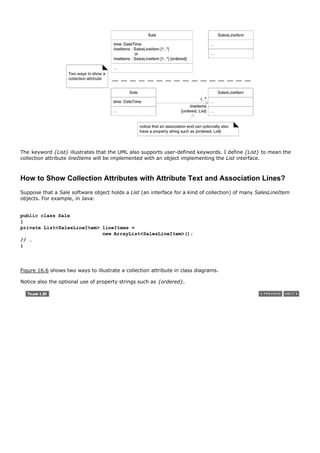
![16.5. Note Symbols: Notes, Comments, Constraints, and Method
Bodies
Note symbols can be used on any UML diagram, but are especially common on class diagrams. A UML note
symbol is displayed as a dog-eared rectangle with a dashed line to the annotated element; they've already
been used throughout the book (for example, Figure 16.6). A note symbol may represent several things, such
as:
a UML note or comment, which by definition have no semantic impact
a UML constraint, in which case it must be encased in braces '{…}' (see Figure 16.14)
a method bodythe implementation of a UML operation (see Figure 16.7)
Figure 16.7. How to show a method body in a class diagram.
[View full size image]](https://image.slidesharecdn.com/softwaredevleopment-100607174022-phpapp01/85/Software-Development-361-320.jpg)


![16.7. Keywords
A UML keyword is a textual adornment to categorize a model element. For example, the keyword to categorize
that a classifier box is an interface is (shocking surprise!) «interface». Figure 16.1 illustrates the «interface»
keyword. The «actor» keyword was used on p. 91 to replace the human stick-figure actor icon with a class box
to model computer-system or robotic actors.
Guideline: When sketching UMLwhen we want speed, ease, and creative flowmodelers often simplify keywords
to something like '<interface>' or '<I>'.
Most keywords are shown in guillemet (« »)[2] but some are shown in curly braces, such as {abstract}, which is
a constraint containing the abstract keyword. In general, when a UML element says it can have a "property
string"such as a UML operation and UML association end havesome of the property string terms will be
keywords (and some may be user defined terms) used in the curly brace format.
[2] Note that in UML 1, guillemet (« ») were only used for stereotypes. In UML 2, guillemets are used for both keywords and stereotypes.
constraints p. 265
Figure 16.1 illustrates both the «interface» and {abstract} keywords.
A few sample predefined UML keywords include:[3]
[3] There are many keywords. Refer to the UML specification for details.
Keyword Meaning Example Usage
«actor» classifier is an actor in class diagram, above classifier name
«interface» classifier is an interface in class diagram, above classifier name
{abstract} abstract element; can't be in class diagrams, after classifier name or
instantiated operation name
{ordered} a set of objects have some imposed in class diagrams, at an association end
order](https://image.slidesharecdn.com/softwaredevleopment-100607174022-phpapp01/85/Software-Development-364-320.jpg)
![16.8. Stereotypes, Profiles, and Tags
As with keywords, stereotypes are shown with guillemets symbols[4], such as «authorship». But, they are not
keywords, which can be confusing. A stereotype represents a refinement of an existing modeling concept and
is defined within a UML profileinformally, a collection of related stereotypes, tags, and constraints to specialize
the use of the UML for a specific domain or platform, such as a UML profile for project management or for data
modeling.
[4]
Guillemets are special single-character brackets most widely known by their use in French typography to indicate a quote. Typographically
challenged tool vendors often substitute two angle brackets ('<< >>') for the more elegant '« »'.
The UML predefines many stereotypes[5], such as «destroy» (used on sequence diagrams), and also allows
user-defined ones. Thus, stereotypes provide an extension mechanism in the UML.
[5] See the UML specification.
For example, Figure 16.8 shows a stereotype declaration, and its use. The stereotype declares a set of tags,
using the attribute syntax. When an element (such as the Square class) is marked with a stereotype, all the
tags apply to the element, and can be assigned values.
Figure 16.8. Stereotype declaration and use.
[View full size image]](https://image.slidesharecdn.com/softwaredevleopment-100607174022-phpapp01/85/Software-Development-365-320.jpg)
![16.9. UML Properties and Property Strings
In the UML, a property is "a named value denoting a characteristic of an element. A property has semantic
impact." [OMG03b]. Some properties are predefined in the UML, such as visibilitya property of an operation.
Others can be user-defined.
Properties of elements may be presented in many ways, but a textual approach is to use the UML property
string {name1=value1, name2=value2} format, such as {abstract, visibility=public}. Some properties are
shown without a value, such as {abstract}; this usually implies a boolean property, shorthand for
{abstract=true}. Note that {abstract} is both an example of a constraint and a property string.
constraint p. 265](https://image.slidesharecdn.com/softwaredevleopment-100607174022-phpapp01/85/Software-Development-366-320.jpg)
![16.10. Generalization, Abstract Classes, Abstract Operations
Generalization in the UML is shown with a solid line and fat triangular arrow from the subclass to superclass
(see Figure 16.1). What does it mean? In the UML, to quote:
Generalization A taxonomic relationship between a more general classifier and a more specific classifier.
Each instance of the specific classifier is also an indirect instance of the general classifier. Thus, the specific
classifier indirectly has features of the more general classifier. [OMG03b]
Is this the same as OO programming language (OOPL) inheritance? It depends. In a domain model
conceptual-perspective class diagram, the answer is no. Rather, it implies the superclass is a superset and the
subclass is a subset. On the other hand, in a DCD software-perspective class diagram, it implies OOPL
inheritance from the superclass to subclass.
As shown in Figure 16.1, abstract classes and operations can be shown either with an {abstract} tag (useful
when sketching UML) or by italicizing the name (easy to support in a UML tool).
The opposite case, final classes and operations that can't be overridden in subclasses, are shown with the
{leaf} tag.](https://image.slidesharecdn.com/softwaredevleopment-100607174022-phpapp01/85/Software-Development-367-320.jpg)


![Dependency Labels
To show the type of dependency, or to help a tool with code generation, the dependency line can be labeled with
keywords or stereotypes.[6] See Figure 16.11.
[6] See the UML specification for many predefined dependency labels.
Figure 16.11. Optional dependency labels in the UML.
[View full size image]](https://image.slidesharecdn.com/softwaredevleopment-100607174022-phpapp01/85/Software-Development-370-320.jpg)
![16.12. Interfaces
The UML provides several ways to show interface implementation, providing an interface to clients, and
interface dependency (a required interface). In the UML, interface implementation is formally called
interface realization. See Figure 16.12.
Figure 16.12. Different notations to show interfaces in UML.
[View full size image]
The socket notation is new to UML 2. It's useful to indicate "Class X requires (uses) interface Y" without
drawing a line pointing to interface Y.](https://image.slidesharecdn.com/softwaredevleopment-100607174022-phpapp01/85/Software-Development-371-320.jpg)
![16.13. Composition Over Aggregation
Aggregation is a vague kind of association in the UML that loosely suggests whole-part relationships (as do
many ordinary associations). It has no meaningful distinct semantics in the UML versus a plain association, but
the term is defined in the UML. Why? To quote Rumbaugh (one of the original and key UML creators):
In spite of the few semantics attached to aggregation, everybody thinks it is necessary (for different
reasons). Think of it as a modeling placebo. [RJB04]
Guideline: Therefore, following the advice of UML creators, don't bother to use aggregation in the UML; rather,
use composition when appropriate.
Composition, also known as composite aggregation, is a strong kind of whole-part aggregation and is useful
to show in some models. A composition relationship implies that 1) an instance of the part (such as a Square)
belongs to only one composite instance (such as one Board) at a time, 2) the part must always belong to a
composite (no free-floating Fingers), and 3) the composite is responsible for the creation and deletion of its
partseither by itself creating/deleting the parts, or by collaborating with other objects. Related to this constraint
is that if the composite is destroyed, its parts must either be destroyed, or attached to another compositeno
free-floating Fingers allowed! For example, if a physical paper Monopoly game board is destroyed, we think of
the squares as being destroyed as well (a conceptual perspective). Likewise, if a software Board object is
destroyed, its software Square objects are destroyed, in a DCD software perspective.
The UML notation for composition is a filled diamond on an association line, at the composite end of the line (see
Figure 16.13).
Figure 16.13. Composition in the UML.
[View full size image]
Guideline: The association name in composition is always implicitly some variation of "Has-part," therefore
don't bother to explicitly name the association.](https://image.slidesharecdn.com/softwaredevleopment-100607174022-phpapp01/85/Software-Development-372-320.jpg)
![16.14. Constraints
Constraints may be used on most UML diagrams, but are especially common on class diagrams. A UML
constraint is a restriction or condition on a UML element. It is visualized in text between braces; for example:
{ size >= 0 }. The text may be natural language or anything else, such as UML's formal specification language,
the Object Constraint Language (OCL) [WK99]. See Figure 16.14.
Figure 16.14. Constraints](https://image.slidesharecdn.com/softwaredevleopment-100607174022-phpapp01/85/Software-Development-373-320.jpg)


![16.17. Singleton Classes
In the world of OO design patterns, there is one that is especially common, called the Singleton pattern. It is
explained later, but an implication of the pattern is that there is only one instance of a class instantiatednever
two. In other words, it is a "singleton" instance. In a UML diagram, such a class can be marked with a '1' in the
upper right corner of the name compartment. See Figure 16.17.
Figure 16.17. Showing a singleton.
[View full size image]
Singleton p. 442](https://image.slidesharecdn.com/softwaredevleopment-100607174022-phpapp01/85/Software-Development-376-320.jpg)
![16.18. Template Classes and Interfaces
Many languages (Java, C++, …) support templatized types, also known (with shades of variant meanings) as
templates, parameterized types, and generics.[7] They are most commonly used for the element type of
collection classes, such as the elements of lists and maps. For example, in Java, suppose that a Board software
object holds a List (an interface for a kind of collection) of many Squares. And, the concrete class that
implements the List interface is an ArrayList:
[7] Motivations for template classes include increased type safety and performance.
public class Board
{
private List<Square> squares = new ArrayList<Square>();
// …
}
Notice that the List interface and the ArrayList class (that implements the List interface) are parameterized with
the element type Square. How to show template classes and interfaces in the UML? Figure 16.18 illustrates.
Figure 16.18. Templates in the UML.
[View full size image]](https://image.slidesharecdn.com/softwaredevleopment-100607174022-phpapp01/85/Software-Development-377-320.jpg)


![16.21. What's the Relationship Between Interaction and Class
Diagrams?
When we draw interaction diagrams, a set of classes and their methods emerge from the creative design
process of dynamic object modeling. For example, if we started with the (trivial for explanation) makePayment
sequence diagram in Figure 16.21, we see that a Register and Sale class definition in a class diagram can be
obviously derived.
Figure 16.21. The influence of interaction diagrams on class diagrams.
[View full size image]
Thus, from interaction diagrams the definitions of class diagrams can be generated. This suggests a linear
ordering of drawing interaction diagrams before class diagrams, but in practice, especially when following the
agile modeling practice of models in parallel, these complementary dynamic and static views are drawn
concurrently. For example, 10 minutes on one, then 10 on the other.
Guideline: A good UML tool should automatically support changes in one diagram being reflected in the other.
If wall sketching, use one wall for interaction diagrams, and an adjacent wall for class diagrams.](https://image.slidesharecdn.com/softwaredevleopment-100607174022-phpapp01/85/Software-Development-380-320.jpg)
![Chapter 17. GRASP: Designing Objects with
Responsibilities
Understanding responsibilities is key to good object-oriented design.
Martin Fowler
Objectives
Learn to apply five of the GRASP principles or patterns for OOD.
This chapter and the next contribute significantly to an understanding of core OO design (OOD). OOD is
sometimes taught as some variation of the following:
After identifying your requirements and creating a domain model, then add methods to the appropriate
classes, and define the messaging between the objects to fulfill the requirements.
Ouch! Such vague advice doesn't help us, because deep principles and issues are involved. Deciding what
methods belong where and how objects should interact carries consequences and should be undertaken
seriously. Mastering OODand this is its intricate charminvolves a large set of soft principles, with many degrees
of freedom. It isn't magicthe patterns can be named (important!), explained, and applied. Examples help.
Practice helps. And this small step helps: After studying these case studies, try recreating (from memory) the
Monopoly solution on walls with partners, and apply the principles, such as Information Expert.
[View full size image]](https://image.slidesharecdn.com/softwaredevleopment-100607174022-phpapp01/85/Software-Development-381-320.jpg)

![17.2. Object Design: Example Inputs, Activities, and Outputs
This section summarizes a big-picture example of design in an iterative method:
What's been done? Prior activities (e.g., workshop) and artifacts.
How do things relate? Influence of prior artifacts (e.g., use cases) on OO design.
How much design modeling to do, and how?
What's the output?
Especially, I'd like you to understand how the analysis artifacts relate to object design.
What Are Inputs to Object Design?
Let's start with "process" inputs. Assume we are developers working on the POS NextGen project, and the
following scenario is true:
The first two-day requirements workshop is The chief architect and business agree to implement
finished. and test some scenarios of Process Sale in the
first three-week timeboxed iteration.
Three of the twenty use casesthose that are the Other artifacts have been started: Supplementary
most architecturally significant and of high business Specification, Glossary, and Domain Model.
valuehave been analyzed in detail, including, of course,
the Process Sale use case. (The UP recommends, as
typical with iterative methods, analyzing only
10%20% of the requirements in detail before
starting to program.)
Programming experiments have resolved the show- The chief architect has drawn some ideas for the
stopper technical questions, such as whether a Java large-scale logical architecture, using UML
Swing UI will work on a touch screen. package diagrams. This is part of the UP Design
Model.
What are the artifact inputs and their relationship to object design?[1] They are summarized in Figure 17.1 and
in the following table.
[1] Other artifact inputs could include design documents for an existing system being modified. It's also useful to reverse-engineer existing code into
UML package diagrams to see the large-scale logical structure and some class and sequence diagrams.
Figure 17.1. Artifact relationships emphasizing influence on OO design.
[View full size image]](https://image.slidesharecdn.com/softwaredevleopment-100607174022-phpapp01/85/Software-Development-383-320.jpg)
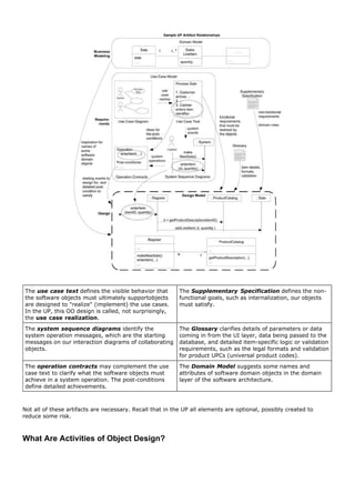
![We're ready to take off our analyst hats and put on our designer-modeler hats.
Given one or more of these inputs, developers 1) start immediately coding (ideally with test-first
development), 2) start some UML modeling for the object design, or 3) start with another modeling technique,
such as CRC cards.[2]
[2] All of these approaches are skillful depending on context and person.
test first p. 386
In the UML case, the real point is not the UML, but visual modelingusing a language that allows us to explore
more visually than we can with just raw text. In this case, for example, we draw both interaction diagrams and
complementary class diagrams (dynamic and static modeling) during one modeling day. And most importantly,
during the drawing (and coding) activity we apply various OO design principles, such as GRASP and the Gang-
of-Four (GoF) design patterns. The overall approach to doing the OO design modeling will be based on the
metaphor of responsibility-driven design (RDD), thinking about how to assign responsibilities to
collaborating objects.
GRASP p. 277
GoF p. 435
RDD p. 276
This and subsequent chapters explore what it means to apply RDD, GRASP, and some of the GoF
design patterns.
On the modeling day, perhaps the team works in small groups for 26 hours either at the walls or with software
modeling tools, doing different kinds of modeling for the difficult, creative parts of the design. This could include
UI, OO, and database modeling with UML drawings, prototyping tools, sketches, and so forth.
During UML drawing, we adopt the realistic attitude (also promoted in agile modeling) that we are drawing the
models primarily to understand and communicate, not to document. Of course, we expect some of the UML
diagrams to be useful input to the definition (or automated code generation with a UML tool) of the code.
On Tuesdaystill early in the three-week timeboxed iterationthe team stops modeling and puts on programmer
hats to avoid a waterfall mentality of over-modeling before programming.
What Are the Outputs?](https://image.slidesharecdn.com/softwaredevleopment-100607174022-phpapp01/85/Software-Development-385-320.jpg)

![17.3. Responsibilities and Responsibility-Driven Design
A popular way of thinking about the design of software objects and also larger-scale components[3] is in terms
of responsibilities, roles, and collaborations. This is part of a larger approach called responsibility-driven
design or RDD [WM02].
[3] Thinking in terms of responsibilities can apply at any scale of softwarefrom a small object to a system of systems.
In RDD, we think of software objects as having responsibilitiesan abstraction of what they do. The UML defines a
responsibility as "a contract or obligation of a classifier" [OMG03b]. Responsibilities are related to the
obligations or behavior of an object in terms of its role. Basically, these responsibilities are of the following two
types: doing and knowing.
Doing responsibilities of an object include:
doing something itself, such as creating an object or doing a calculation
initiating action in other objects
controlling and coordinating activities in other objects
Knowing responsibilities of an object include:
knowing about private encapsulated data
knowing about related objects
knowing about things it can derive or calculate
Responsibilities are assigned to classes of objects during object design. For example, I may declare that "a Sale
is responsible for creating SalesLineItems" (a doing), or "a Sale is responsible for knowing its total" (a knowing).
Guideline: For software domain objects, the domain model, because of the attributes and associations it
illustrates, often inspires the relevant responsibilities related to "knowing." For example, if the domain model
Sale class has a time attribute, it's natural by the goal of low representational gap that a software Sale class
knows its time.
low representational gap p. 138
The translation of responsibilities into classes and methods is influenced by the granularity of the responsibility.
Big responsibilities take hundreds of classes and methods. Little responsibilities might take one method. For
example, the responsibility to "provide access to relational databases" may involve two hundred classes and
thousands of methods, packaged in a subsystem. By contrast, the responsibility to "create a Sale" may involve
only one method in one class.
A responsibility is not the same thing as a methodit's an abstractionbut methods fulfill responsibilities.
RDD also includes the idea of collaboration. Responsibilities are implemented by means of methods that either
act alone or collaborate with other methods and objects. For example, the Sale class might define one or more
methods to know its total; say, a method named getTotal. To fulfill that responsibility, the Sale may collaborate
with other objects, such as sending a getSubtotal message to each SalesLineItem object asking for its subtotal.](https://image.slidesharecdn.com/softwaredevleopment-100607174022-phpapp01/85/Software-Development-387-320.jpg)


![New pattern should be considered an oxymoron if it describes a new idea. The very term "pattern" suggests a
long-repeating thing. The point of design patterns is not to express new design ideas. Quite the oppositegreat
patterns attempt to codify existing tried-and-true knowledge, idioms, and principles; the more honed, old, and
widely used, the better.
Consequently, the GRASP patterns don't state new ideas; they name and codify widely used basic principles. To
an OO design expert, the GRASP patternsby idea if not by namewill appear fundamental and familiar. That's the
point!
The Gang-of-Four Design Patterns Book
The idea of named patterns in software comes from Kent Beck (also of Extreme Programming fame) in the
mid 1980s.[4] However, 1994 was a major milestone in the history of patterns, OO design, and software design
books: The massive-selling and hugely influential book Design Patterns [GHJV95][5] was published, authored by
Gamma, Helm, Johnson, and Vlissides. The book, considered the "Bible" of design pattern books, describes 23
patterns for OO design, with names such as Strategy and Adapter. These 23 patterns, authored by four people,
are therefore called the Gang of Four[6] (or GoF) design patterns.
[4] The notion of patterns originated with the (building) architectural patterns of Christopher Alexander [AIS77]. Patterns for software originated in the
1980s with Kent Beck, who became aware of Alexander's pattern work in architecture, and then were developed by Beck with Ward Cunningham
[BC87, Beck94] at Tektronix.
[5] Publishers list the publication date as 1995, but it was released October 1994.
[6] Also a subtle joke related to mid-1970s Chinese politics following Mao's death.
However, Design Patterns isn't an introductory book; it assumes significant prior OO design and programming
knowledge, and most code examples are in C++.
Laterintermediatechapters of this book, especially Chapter 26 (p. 435), Chapter 35 (p. 579), and Chapter 38 (p.
625) introduce many of the most frequently used GoF design patterns and apply them to our case studies. Also:
See "Contents by Major Topics" on page ix.
It is a key goal of this text to learn both GRASP and essential GoF patterns.
Is GRASP a Set of Patterns or Principles?
GRASP defines nine basic OO design principles or basic building blocks in design. Some have asked, "Doesn't
GRASP describe principles rather than patterns?" One answer is in the words of the Gang of Four authors, from](https://image.slidesharecdn.com/softwaredevleopment-100607174022-phpapp01/85/Software-Development-392-320.jpg)


![17.8. A Short Example of Object Design with GRASP
Following sections explore GRASP in more detail, but let's start with a shorter example to see the big ideas,
applied to the Monopoly case study. There are nine GRASP patterns; this example applies the following subset:
Creator
Information Expert
Low Coupling
Controller
High Cohesion
All the GRASP patterns are summarized on the inside front cover of this book.
Creator
Problem: Who creates the Square object?
One of the first problems you have to consider in OO design is: Who creates object X? This is a doing
responsibility. For example, in the Monopoly case study, who creates a Square software object? Now, any object
can create a Square, but what would many OO developers choose? And why?
How about having a Dog object (i.e., some arbitrary class) be the creator? No! We can feel it in our bones.
Why? Becauseand this is the critical pointit doesn't appeal to our mental model of the domain. Dog doesn't
support low representational gap (LRG) between how we think of the domain and a straightforward
correspondence with software objects. I've done this problem with literally thousands of developers, and
virtually every one, from India to the USA, will say, "Make the Board object create the Squares." Interesting! It
reflects an "intuition" that OO software developers often (exceptions are explored later) want "containers" to
create the things "contained," such as Boards creating Squares.
By the way, why we are defining software classes with the names Square and Board, rather than the names
AB324 and ZC17? Answer: By LRG. This connects the UP Domain Model to the UP Design Model, or our mental
model of the domain to its realization in the domain layer of the software architecture.
With that as background, here's the definition of the Creator pattern[7]:
[7] Alternate creation patterns, such as Concrete Factory and Abstract Factory, are discussed later.](https://image.slidesharecdn.com/softwaredevleopment-100607174022-phpapp01/85/Software-Development-395-320.jpg)


![Figure 17.7. Evaluating the effect of coupling on this design.
[View full size image]
But let's evaluate the total coupling with this poor Dog design versus our original design where Board does
getSquare. In the Dog case, the Dog and the Board must both know about Square objects (two objects have
coupling to Square); in the Board case, only Board must know about Square objects (one object has coupling to
Square). Thus, the overall coupling is lower with the Board design, and all other things being equal, it is better
than the Dog design, in terms of supporting the goal of Low Coupling.
At a higher-goal level, why is Low Coupling desirable? In other words, why would we want to reduce the impact
of change? Because Low Coupling tends to reduce the time, effort, and defects in modifying software. That's a
short answer, but one with big implications in building and maintaining software!
Key Point: Expert Supports Low Coupling
To return to the motivation for Information Expert: it guides us to a choice that supports Low
Coupling. Expert asks us to find the object that has most of the information required for the
responsibility (e.g., Board) and assign responsibility there.
If we put the responsibility anywhere else (e.g., Dog), the overall coupling will be higher because
more information or objects must be shared away from their original source or home, as the
squares in the Map collection had to be shared with the Dog, away from their home in the Board.
Applying UML: Please note a few UML elements in the sequence diagram in Figure 17.7:
The return value variable sqs from the getAllSquares message is also used to name the lifeline object in
sqs : Map<Square> (e.g., a collection of type Map that holds Square objects). Referencing a return value
variable in a lifeline box (to send it messages) is common.
The variable s in the starting getSquare message and the variable s in the later get message refer to the
same object.
The message expression s = get(name) : Square indicates that the type of s is a reference to a Square
instance.](https://image.slidesharecdn.com/softwaredevleopment-100607174022-phpapp01/85/Software-Development-399-320.jpg)
![Controller
A simple layered architecture has a UI layer and a domain layer, among others. Actors, such as the human
observer in the Monopoly game, generate UI events, such as clicking on a button with a mouse to play the
game. The UI software objects (in Java for example, a JFrame window and a JButton button) must then react to
the mouse click event and ultimately cause the game to play.
From the Model-View Separation Principle, we know the UI objects should not contain application or "business"
logic such as calculating a player's move. Therefore, once the UI objects pick up the mouse event, they need to
delegate (forward the task to another object) the request to domain objects in the domain layer.
Model-View Separation p. 209
The Controller pattern answers this simple question: What first object after or beyond the UI layer should
receive the message from the UI layer?
To tie this back to system sequence diagrams, as a review of Figure 17.8 shows, the key system operation is
playGame. Somehow the human observer generates a playGame request (probably by clicking on a GUI button
labeled "Play Game") and the system responds.
Figure 17.8. SSD for the Monopoly game. Note the playGame operation.
Figure 17.9 illustrates a finer-grained look at what's going on, assuming a Java Swing GUI JFrame window and
JButton button.[8] Clicking on a JButton sends an actionPerformed message to some object, often to the JFrame
window itself, as we see in Figure 17.9. Thenand this is the key pointthe JFrame window must adapt that
actionPerformed message into something more semantically meaningful, such as a playGame message (to
correspond to the SSD analysis), and delegate the playGame message to a domain object in the domain layer.
[8] Similar objects, messages, and collaboration patterns apply to .NET, Python, etc.
Figure 17.9. Who is the Controller for the playGame system operation?](https://image.slidesharecdn.com/softwaredevleopment-100607174022-phpapp01/85/Software-Development-400-320.jpg)
![[View full size image]
Do you see the connection between the SSD system operations and the detailed object design
from the UI to domain layer? This is important.
Thus, Controller deals with a basic question in OO design: How to connect the UI layer to the application logic
layer? Should the Board be the first object to receive the playGame message from the UI layer? Or something
else?
In some OOA/D methods, the name controller was given to the application logic object that received and
"controlled" (coordinated) handling the request.
The Controller pattern offers the following advice:
Name: Controller
Problem: What first object beyond the UI layer receives and coordinates ("controls") a system
operation?
Solution: (advice) Assign the responsibility to an object representing one of these choices:
Represents the overall "system," a "root object," a device that the software is
running within, or a major subsystem (these are all variations of a facade
controller).
Represents a use case scenario within which the system operation occurs (a use
case or session controller)
Let's consider these options:
Option 1: Represents the overall "system," or a "root object"such as an object called MonopolyGame.
Option 1: Represents a device that the software is running withinthis option appertains to specialized hardware
devices such as a phone or a bank cash machine (e.g., software class Phone or BankCashMachine); it doesn't
apply in this case.
Option 2: Represents the use case or session. The use case that the playGame system operation occurs within
is called Play Monopoly Game. Thus, a software class such as PlayMonopolyGameHandler (appending "…Handler"
or "…Session" is an idiom in OO design when this version is used).
Option #1, class MonopolyGame, is reasonable if there are only a few system operations (more on the trade-offs
when we discuss High Cohesion). Therefore, Figure 17.10 illustrates the design decision based on Controller.](https://image.slidesharecdn.com/softwaredevleopment-100607174022-phpapp01/85/Software-Development-401-320.jpg)
![Figure 17.10. Applying the Controller patternusing MonopolyGame. Connecting the
UI layer to the domain layer of software objects.
High Cohesion
Based on the Controller decision, we are now at the design point shown in the sequence diagram to the right.
The detailed design discussion of what comes nextconsistently and methodically applying GRASPis explored in a
following chapter, but right now we have two contrasting design approaches worth considering, illustrated in
Figure 17.11.
Figure 17.11. Contrasting the level of cohesion in different designs.
[View full size image]](https://image.slidesharecdn.com/softwaredevleopment-100607174022-phpapp01/85/Software-Development-402-320.jpg)

![17.9. Applying GRASP to Object Design
GRASP stands for General Responsibility Assignment Software Patterns.[9] The name was chosen to suggest the
importance of grasping these principles to successfully design object-oriented software.
[9] Technically, one should write "GRAS Patterns" rather than "GRASP Patterns," but the latter sounds better.
All nine GRASP patterns are summarized on the inside front cover of this book.
Understanding and being able to apply the ideas behind GRASPwhile coding or while drawing interaction and
class diagramsenables developers new to object technology needs to master these basic principles as quickly as
possible; they form a foundation for designing OO systems.
There are nine GRASP patterns:
Creator Controller Pure Fabrication
Information Expert High Cohesion Indirection
Low Coupling Polymorphism Protected
Variations
The remainder of this chapter reexamines the first five in more detail; the remaining four are introduced in
Chapter 25 starting on p. 413.](https://image.slidesharecdn.com/softwaredevleopment-100607174022-phpapp01/85/Software-Development-404-320.jpg)
![17.10. Creator
Problem
Who should be responsible for creating a new instance of some class?
The creation of objects is one of the most common activities in an object-oriented system. Consequently, it is
useful to have a general principle for the assignment of creation responsibilities. Assigned well, the design can
support low coupling, increased clarity, encapsulation, and reusability.
Solution
Assign class B the responsibility to create an instance of class A if one of these is true (the more the better):[10]
[10] Other creation patterns, such as Concrete Factory and Abstract Factory, are explored later.
B "contains" or compositely aggregates A.
B records A.
B closely uses A.
B has the initializing data for A that will be passed to A when it is created. Thus B is an Expert with respect
to creating A.
B is a creator of A objects.
If more than one option applies, usually prefer a class B which aggregates or contains class A.
Example
In the NextGen POS application, who should be responsible for creating a SalesLineItem instance? By Creator,
we should look for a class that aggregates, contains, and so on, SalesLineItem instances. Consider the partial
domain model in Figure 17.12.
Figure 17.12. Partial domain model.](https://image.slidesharecdn.com/softwaredevleopment-100607174022-phpapp01/85/Software-Development-405-320.jpg)
![Since a Sale contains (in fact, aggregates) many SalesLineItem objects, the Creator pattern suggests that Sale
is a good candidate to have the responsibility of creating SalesLineItem instances. This leads to the design of
object interactions shown in Figure 17.13.
Figure 17.13. Creating a SalesLineItem.
[View full size image]
This assignment of responsibilities requires that a makeLineItem method be defined in Sale. Once again, the
context in which we considered and decided on these responsibilities was while drawing an interaction diagram.
The method section of a class diagram can then summarize the responsibility assignment results, concretely
realized as methods.
Discussion
Creator guides the assigning of responsibilities related to the creation of objects, a very common task. The basic
intent of the Creator pattern is to find a creator that needs to be connected to the created object in any event.
Choosing it as the creator supports low coupling.
Composite aggregates Part, Container contains Content, and Recorder records. Recorded are all very common
relationships between classes in a class diagram. Creator suggests that the enclosing container or recorder class
is a good candidate for the responsibility of creating the thing contained or recorded. Of course, this is only a
guideline.
Note that we turned to the concept of composition in considering the Creator pattern. A composite object is an
excellent candidate to make its parts.
composite aggregation p. 264
Sometimes you identify a creator by looking for the class that has the initializing data that will be passed in
during creation. This is actually an example of the Expert pattern. Initializing data is passed in during creation
via some kind of initialization method, such as a Java constructor that has parameters. For example, assume
that a Payment instance, when created, needs to be initialized with the Sale total. Since Sale knows the total,
Sale is a candidate creator of the Payment.
Contraindications
Often, creation requires significant complexity, such as using recycled instances for performance, conditionally
creating an instance from one of a family of similar classes based upon some external property value, and so
forth. In these cases, it is advisable to delegate creation to a helper class called a Concrete Factory or an
Abstract Factory [GHJV95] rather than use the class suggested by Creator. Factories are discussed starting on
p. 440.](https://image.slidesharecdn.com/softwaredevleopment-100607174022-phpapp01/85/Software-Development-406-320.jpg)
![Benefits
Low coupling is supported, which implies lower maintenance dependencies and higher opportunities for
reuse. Coupling is probably not increased because the created class is likely already visible to the creator
class, due to the existing associations that motivated its choice as creator.
Related Patterns or Principles
Low Coupling
Concrete Factory and Abstract Factory
Whole-Part [BMRSS96] describes a pattern to define aggregate objects that support encapsulation of
components.](https://image.slidesharecdn.com/softwaredevleopment-100607174022-phpapp01/85/Software-Development-407-320.jpg)

![Figure 17.14. Associations of Sale.
What information do we need to determine the grand total? We need to know about all the SalesLineItem
instances of a sale and the sum of their subtotals. A Sale instance contains these; therefore, by the guideline of
Information Expert, Sale is a suitable class of object for this responsibility; it is an information expert for the
work.
As mentioned, it is in the context of the creation of interaction diagrams that these questions of responsibility
often arise. Imagine we are starting to work through the drawing of diagrams in order to assign responsibilities
to objects. A partial interaction diagram and class diagram in Figure 17.15 illustrate some decisions.
Figure 17.15. Partial interaction and class diagrams.
We are not done yet. What information do we need to determine the line item subtotal? SalesLineItem.quantity
and ProductDescription.price. The SalesLineItem knows its quantity and its associated ProductDescription;
therefore, by Expert, SalesLineItem should determine the subtotal; it is the information expert.
In terms of an interaction diagram, this means that the Sale should send getSubtotal messages to each of the
SalesLineItems and sum the results; this design is shown in Figure 17.16.
Figure 17.16. Calculating the Sale total.
[View full size image]](https://image.slidesharecdn.com/softwaredevleopment-100607174022-phpapp01/85/Software-Development-409-320.jpg)
![To fulfill the responsibility of knowing and answering its subtotal, a SalesLineItem has to know the product price.
The ProductDescription is an information expert on answering its price; therefore, SalesLineItem sends it a
message asking for the product price.
The design is shown in Figure 17.17.
Figure 17.17. Calculating the Sale total.
[View full size image]
In conclusion, to fulfill the responsibility of knowing and answering the sale's total, we assigned three
responsibilities to three design classes of objects as follows.
Design Class Responsibility
Sale knows sale total
SalesLineItem knows line item
subtotal
ProductDescription knows product price
We considered and decided on these responsibilities in the context of drawing an interaction diagram. We could
then summarize the methods in the method section of a class diagram.
The principle by which we assigned each responsibility was Information Expertplacing it with the object that had](https://image.slidesharecdn.com/softwaredevleopment-100607174022-phpapp01/85/Software-Development-410-320.jpg)
![the information needed to fulfill it.
Discussion
Information Expert is frequently used in the assignment of responsibilities; it is a basic guiding principle used
continuously in object design. Expert is not meant to be an obscure or fancy idea; it expresses the common
"intuition" that objects do things related to the information they have.
Notice that the fulfillment of a responsibility often requires information that is spread across different classes of
objects. This implies that many "partial" information experts will collaborate in the task. For example, the sales
total problem ultimately required the collaboration of three classes of objects. Whenever information is spread
across different objects, they will need to interact via messages to share the work.
Expert usually leads to designs where a software object does those operations that are normally done to the
inanimate real-world thing it represents; Peter Coad calls this the "Do It Myself" strategy [Coad95]. For
example, in the real world, without the use of electro-mechanical aids, a sale does not tell you its total; it is an
inanimate thing. Someone calculates the total of the sale. But in object-oriented software land, all software
objects are "alive" or "animated," and they can take on responsibilities and do things. Fundamentally, they do
things related to the information they know. I call this the "animation" principle in object design; it is like being
in a cartoon where everything is alive.
The Information Expert patternlike many things in object technologyhas a real-world analogy. We commonly
give responsibility to individuals who have the information necessary to fulfill a task. For example, in a business,
who should be responsible for creating a profit-and-loss statement? The person who has access to all the
information necessary to create itperhaps the chief financial officer. And just as software objects collaborate
because the information is spread around, so it is with people. The company's chief financial officer may ask
accountants to generate reports on credits and debits.
Contraindications
In some situations, a solution suggested by Expert is undesirable, usually because of problems in coupling and
cohesion (these principles are discussed later in this chapter).
For example, who should be responsible for saving a Sale in a database? Certainly, much of the information to
be saved is in the Sale object, and thus Expert could argue that the responsibility lies in the Sale class. And, by
logical extension of this decision, each class would have its own services to save itself in a database. But acting
on that reasoning leads to problems in cohesion, coupling, and duplication. For example, the Sale class must
now contain logic related to database handling, such as that related to SQL and JDBC (Java Database
Connectivity). The class no longer focuses on just the pure application logic of "being a sale." Now other kinds of
responsibilities lower its cohesion. The class must be coupled to the technical database services of another
subsystem, such as JDBC services, rather than just being coupled to other objects in the domain layer of
software objects, so its coupling increases. And it is likely that similar database logic would be duplicated in
many persistent classes.
All these problems indicate violation of a basic architectural principle: design for a separation of major system
concerns. Keep application logic in one place (such as the domain software objects), keep database logic in
another place (such as a separate persistence services subsystem), and so forth, rather than intermingling
different system concerns in the same component.[11]
[11] See Chapter 33 for a discussion of separation of concerns.
Supporting a separation of major concerns improves coupling and cohesion in a design. Thus, even though by
Expert we could find some justification for putting the responsibility for database services in the Sale class, for
other reasons (usually cohesion and coupling), we'd end up with a poor design.
Benefits
Information encapsulation is maintained since objects use their own information to fulfill tasks. This usually
supports low coupling, which leads to more robust and maintainable systems. Low Coupling is also a
GRASP pattern that is discussed in a following section.
Behavior is distributed across the classes that have the required information, thus encouraging more
cohesive "lightweight" class definitions that are easier to understand and maintain. High cohesion is usually](https://image.slidesharecdn.com/softwaredevleopment-100607174022-phpapp01/85/Software-Development-411-320.jpg)


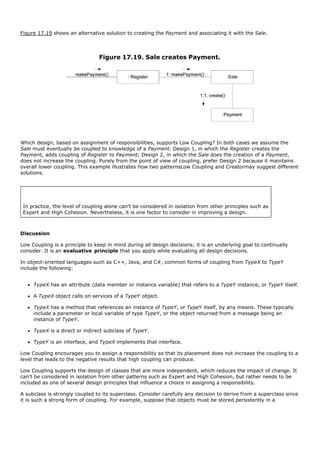
![relational or object database. In this case, you could follow the relatively common design practice of creating an
abstract superclass called PersistentObject from which other classes derive. The disadvantage of this subclassing
is that it highly couples domain objects to a particular technical service and mixes different architectural
concerns, whereas the advantage is automatic inheritance of persistence behavior.
You cannot obtain an absolute measure of when coupling is too high. What is important is that you can gauge
the current degree of coupling and assess whether increasing it will lead to problems. In general, classes that
are inherently generic in nature and with a high probability for reuse should have especially low coupling.
The extreme case of Low Coupling is no coupling between classes. This case offends against a central metaphor
of object technology: a system of connected objects that communicate via messages. Low Coupling taken to
excess yields a poor designone with a few incohesive, bloated, and complex active objects that do all the work,
and with many passive zero-coupled objects that act as simple data repositories. Some moderate degree of
coupling between classes is normal and necessary for creating an object-oriented system in which tasks are
fulfilled by a collaboration between connected objects.
Contraindications
High coupling to stable elements and to pervasive elements is seldom a problem. For example, a J2EE
application can safely couple itself to the Java libraries (java.util, and so on), because they are stable and
widespread.
Pick Your Battles
It is not high coupling per se that is the problem; it is high coupling to elements that are unstable in some
dimension, such as their interface, implementation, or mere presence.
This is an important point: As designers, we can add flexibility, encapsulate details and implementations, and in
general design for lower coupling in many areas of the system. But, if we put effort into "future proofing" or
lowering the coupling when we have no realistic motivation, this is not time well spent.
You must pick your battles in lowering coupling and encapsulating things. Focus on the points of realistic high
instability or evolution. For example, in the NextGen project, we know that different third-party tax calculators
(with unique interfaces) need to be connected to the system. Therefore, designing for low coupling at this
variation point is practical.
Benefits
not affected by changes in other components
simple to understand in isolation
convenient to reuse
Background
Coupling and cohesion are truly fundamental principles in design, and should be appreciated and applied as such
by all software developers. Larry Constantine, also a founder of structured design in the 1970s and a current
advocate of more attention to usability engineering [CL99], was primarily responsible in the 1960s for
identifying and communicating coupling and cohesion as critical principles [Constantine68, CMS74].
Related Patterns
Protected Variation](https://image.slidesharecdn.com/softwaredevleopment-100607174022-phpapp01/85/Software-Development-415-320.jpg)

![During analysis, system operations may be assigned to the class System in some analysis model, to indicate
they are system operations. However, this does not mean that a software class named System fulfills them
during design. Rather, during design, a controller class is assigned the responsibility for system operations (see
Figure 17.21).
Figure 17.21. What object should be the Controller for enterItem?
[View full size image]
Who should be the controller for system events such as enterItem and endSale?
By the Controller pattern, here are some choices:
Represents the overall "system," "root object," device, or subsystem. Register, POSSystem
Represents a receiver or handler of all system events of a use case ProcessSaleHandler,
scenario. ProcessSaleSession
Note that in the domain of POS, a Register (called a POS Terminal) is a specialized device with software running
in it.
In terms of interaction diagrams, one of the examples in Figure 17.22 could be useful.
Figure 17.22. Controller choices.](https://image.slidesharecdn.com/softwaredevleopment-100607174022-phpapp01/85/Software-Development-417-320.jpg)
![The choice of which of these classes is the most appropriate controller is influenced by other factors, which the
following section explores.
During design, the system operations identified during system behavior analysis are assigned to one or more
controller classes, such as Register, as shown in Figure 17.23.
Figure 17.23. Allocation of system operations.
[View full size image]
Discussion
Some get a better sense of applying this pattern with code examples. Look ahead in the Implementation section
on p. 309 for examples in Java for both rich client and Web UIs.
Simply, this is a delegation pattern. In accordance with the understanding that the UI layer shouldn't contain
application logic, UI layer objects must delegate work requests to another layer. When the "other layer" is the
domain layer, the Controller pattern summarizes common choices that you, as an OO developer, make for the
domain object delegate that receives the work requests.
Systems receive external input events, typically involving a GUI operated by a person. Other mediums of input
include external messages, such as in a call-processing telecommunications switch or signals from sensors such
as in process control systems.
In all cases, you must choose a handler for these events. Turn to the Controller pattern for guidance toward
generally accepted, suitable choices. As illustrated in Figure 17.21, the controller is a kind of facade into the](https://image.slidesharecdn.com/softwaredevleopment-100607174022-phpapp01/85/Software-Development-418-320.jpg)
![domain layer from the UI layer.
You will often want to use the same controller class for all the system events of one use case so that the
controller can maintain information about the state of the use case. Such information is useful, for example, to
identify out-of-sequence system events (for example, a makePayment operation before an endSale operation).
Different controllers may be used for different use cases.
A common defect in the design of controllers results from over-assignment of responsibility. A controller then
suffers from bad (low) cohesion, violating the principle of High Cohesion.
Guideline
Normally, a controller should delegate to other objects the work that needs to be done; it
coordinates or controls the activity. It does not do much work itself.
Please see the "Issues and Solutions" section for elaboration.
The first category of controller is a facade controller representing the overall system, device, or a subsystem.
The idea is to choose some class name that suggests a cover, or facade, over the other layers of the application
and that provides the main point of service calls from the UI layer down to other layers. The facade could be an
abstraction of the overall physical unit, such as a Register[12] , TelecommSwitch, Phone, or Robot; a class
representing the entire software system, such as POSSystem; or any other concept which the designer chooses
to represent the overall system or a subsystem, even, for example, ChessGame if it was game software.
[12] Various
terms are used for a physical POS unit, including register, point-of-sale terminal (POST), and so forth. Over time, "register" has come to
embody the notion of both a physical unit and the logical abstraction of the thing that registers sales and payments.
Facade controllers are suitable when there are not "too many" system events, or when the user interface (UI)
cannot redirect system event messages to alternating controllers, such as in a message-processing system.
If you choose a use case controller, then you will have a different controller for each use case. Note that this
kind of controller is not a domain object; it is an artificial construct to support the system (a Pure Fabrication in
terms of the GRASP patterns). For example, if the NextGen application contains use cases such as Process Sale
and Handle Returns, then there may be a ProcessSaleHandler class and so forth.
When should you choose a use case controller? Consider it an alternative when placing the responsibilities in a
facade controller leads to designs with low cohesion or high coupling, typically when the facade controller is
becoming "bloated" with excessive responsibilities. A use case controller is a good choice when there are many
system events across different processes; it factors their handling into manageable separate classes and also
provides a basis for knowing and reasoning about the state of the current scenario in progress.
In the UP and Jacobson's older Objectory method [Jacobson92], there are the (optional) concepts of boundary,
control, and entity classes. Boundary objects are abstractions of the interfaces, entity objects are the
application-independent (and typically persistent) domain software objects, and control objects are use case
handlers as described in this Controller pattern.
A important corollary of the Controller pattern is that UI objects (for example, window or button objects) and
the UI layer should not have responsibility for fulfilling system events. In other words, system operations should
be handled in the application logic or domain layers of objects rather than in the UI layer of a system. See the
"Issues and Solutions" section for an example.
Web UIs and Server-Side Application of Controller
Please see p. 310 for a server-side example using Java Strutsa popular framework.
A similar delegation approach can be used in ASP.NET and WebForms: The "code behind" file that contains
event handlers for Web browser button clicks will obtain a reference to a domain controller object (e.g., a](https://image.slidesharecdn.com/softwaredevleopment-100607174022-phpapp01/85/Software-Development-419-320.jpg)


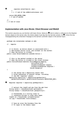

![Figure 17.24. Desirable coupling of UI layer to domain layer.
[View full size image]
Notice that the SaleJFrame classpart of the UI layerdelegates the enterItem request to the Register object. It
did not get involved in processing the operation or deciding how to handle it; the window only delegated it to
another layer.
Assigning the responsibility for system operations to objects in the application or domain layer by using the
Controller pattern rather than the UI layer can increase reuse potential. If a UI layer object (like the
SaleJFrame) handles a system operation that represents part of a business process, then business process logic
would be contained in an interface (for example, window-like) object; the opportunity for reuse of the business
logic then diminishes because of its coupling to a particular interface and application. Consequently, the design
in Figure 17.25 is undesirable.
Figure 17.25. Less desirable coupling of interface layer to domain layer.
[View full size image]](https://image.slidesharecdn.com/softwaredevleopment-100607174022-phpapp01/85/Software-Development-424-320.jpg)
![Placing system operation responsibility in a domain object controller makes it easier to reuse the program logic
supporting the associated business process in future applications. It also makes it easier to unplug the UI layer
and use a different UI framework or technology, or to run the system in an offline "batch" mode.
Message Handling Systems and the Command Pattern
Some applications are message-handling systems or servers that receive requests from other processes. A
telecommunications switch is a common example. In such systems, the design of the interface and controller is
somewhat different. The details are explored in a later chapter, but in essence, a common solution is to use the
Command pattern [GHJV95] and Command Processor pattern [BMRSS96], introduced in Chapter 38.
Related Patterns
Command In a message-handling system, each message may be represented and handled by a separate
Command object [GHJV95].
Facade A facade controller is a kind of Facade [GHJV95].
Layers This is a POSA pattern [BMRSS96]. Placing domain logic in the domain layer rather than the
presentation layer is part of the Layers pattern.
Pure Fabrication This GRASP pattern is an arbitrary creation of the designer, not a software class whose
name is inspired by the Domain Model. A use case controller is a kind of Pure Fabrication.](https://image.slidesharecdn.com/softwaredevleopment-100607174022-phpapp01/85/Software-Development-425-320.jpg)

![This assignment of responsibilities places the responsibility for making a payment in the Register. The Register
is taking on part of the responsibility for fulfilling the makePayment system operation.
In this isolated example, this is acceptable; but if we continue to make the Register class responsible for doing
some or most of the work related to more and more system operations, it will become increasingly burdened
with tasks and become incohesive.
Imagine fifty system operations, all received by Register. If Register did the work related to each, it would
become a "bloated" incohesive object. The point is not that this single Payment creation task in itself makes the
Register incohesive, but as part of a larger picture of overall responsibility assignment, it may suggest a trend
toward low cohesion.
And most important in terms of developing skills as object designers, regardless of the final design choice, is the
valuable achievement that at least we know to consider the impact on cohesion.
By contrast, as shown in Figure 17.27, the second design delegates the payment creation responsibility to the
Sale supports higher cohesion in the Register.
Figure 17.27. Sale creates Payment.
Since the second design supports both high cohesion and low coupling, it is desirable.
In practice, the level of cohesion alone can't be considered in isolation from other responsibilities
and other principles such as Expert and Low Coupling.
Discussion
Like Low Coupling, High Cohesion is a principle to keep in mind during all design decisions; it is an underlying
goal to continually consider. It is an evaluative principle that a designer applies while evaluating all design
decisions.
Grady Booch describes high functional cohesion as existing when the elements of a component (such as a class)
"all work together to provide some well-bounded behavior" [Booch94].
Here are some scenarios that illustrate varying degrees of functional cohesion:
1. Very low cohesion A class is solely responsible for many things in very different functional areas.](https://image.slidesharecdn.com/softwaredevleopment-100607174022-phpapp01/85/Software-Development-427-320.jpg)
![1.
Assume the existence of a class called RDB-RPC-Interface which is completely responsible for
interacting with relational databases and for handling remote procedure calls. These are two vastly
different functional areas, and each requires lots of supporting code. The responsibilities should be
split into a family of classes related to RDB access and a family related to RPC support.
2. Low cohesion A class has sole responsibility for a complex task in one functional area.
Assume the existence of a class called RDBInterface which is completely responsible for interacting
with relational databases. The methods of the class are all related, but there are lots of them, and a
tremendous amount of supporting code; there may be hundreds or thousands of methods. The class
should split into a family of lightweight classes sharing the work to provide RDB access.
3. High cohesion A class has moderate responsibilities in one functional area and collaborates with other
classes to fulfill tasks.
Assume the existence of a class called RDBInterface that is only partially responsible for interacting
with relational databases. It interacts with a dozen other classes related to RDB access in order to
retrieve and save objects.
4. Moderate cohesion A class has lightweight and sole responsibilities in a few different areas that are logically
related to the class concept but not to each other.
Assume the existence of a class called Company that is completely responsible for (a) knowing its
employees and (b) knowing its financial information. These two areas are not strongly related to each
other, although both are logically related to the concept of a company. In addition, the total number
of public methods is small, as is the amount of supporting code.
As a rule of thumb, a class with high cohesion has a relatively small number of methods, with highly related
functionality, and does not do too much work. It collaborates with other objects to share the effort if the task is
large.
A class with high cohesion is advantageous because it is relatively easy to maintain, understand, and reuse. The
high degree of related functionality, combined with a small number of operations, also simplifies maintenance
and enhancements. The fine grain of highly related functionality also supports increased reuse potential.
The High Cohesion patternlike many things in object technologyhas a real-world analogy. It is a common
observation that if a person takes on too many unrelated responsibilitiesespecially ones that should properly be
delegated to othersthen the person is not effective. This is observed in some managers who have not learned
how to delegate. These people suffer from low cohesion; they are ready to become "unglued."
Another Classic Principle: Modular Design
Coupling and cohesion are old principles in software design; designing with objects does not imply ignoring well-
established fundamentals. Another of thesewhich is strongly related to coupling and cohesionis to promote
modular design. To quote:
Modularity is the property of a system that has been decomposed into a set of cohesive and loosely
coupled modules [Booch94].
We promote a modular design by creating methods and classes with high cohesion. At the basic object level, we
achieve modularity by designing each method with a clear, single purpose and by grouping a related set of
concerns into a class.
Cohesion and Coupling; Yin and Yang](https://image.slidesharecdn.com/softwaredevleopment-100607174022-phpapp01/85/Software-Development-428-320.jpg)

![17.15. Recommended Resources
The metaphor of RDD especially emebged from the influential object work in Smalltalk at Tektronix in Portland,
from Kent Beck, Ward Cunningham, Rebecca Wirfs-Brock, and others. Designing Object-Oriented Software
[WWW90] is the landmark text, and is as relevant today as when it was written. Wirfs-Brock has more recently
released another RDD text, Object Design: Roles, Responsibilities, and Collaborations [WM02].
Two other recommended texts emphasizing fundamental object design principles are Object-Oriented Design
Heuristics by Riel and Object Models by Coad.](https://image.slidesharecdn.com/softwaredevleopment-100607174022-phpapp01/85/Software-Development-430-320.jpg)
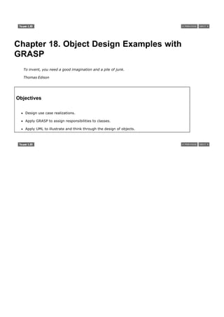
![Introduction
This chapter applies OO design principles and the UML to the case studies, to show larger examples of
reasonably designed objects with responsibilities and collaborations. Please note that the GRASP patterns by
name are not important; they're just a learning aid that helps us think methodically about basic OO design.
[View full size image]
Key Point
The assignment of responsibilities and design of collaborations are very important and creative
steps during design, both while diagraming and while coding.
The No-Magic Zone
This chapter invites you to learn through detailed explanations how an OO developer might reason while
designing by principles. In fact, over a short time of practice, these principles become ingrained, and some of
the decision-making happens almost at a subconscious level.
But first, I wish to exhaustively illustrate that no "magic" is needed in object design, no unjustifiable decisions
are necessaryassignment of responsibilities and the choice of collaborations can be rationally explained and
learned. OO software design really can be more science than art, though there is plenty of room for creativity
and elegant design.](https://image.slidesharecdn.com/softwaredevleopment-100607174022-phpapp01/85/Software-Development-432-320.jpg)
![18.1. What is a Use Case Realization?
The last chapter on basic OO design principles looked at little fragments of design problems. In contrast, this
chapter demonstrates the larger picture of designing the domain objects[1] for an entire use case scenario. You
will see larger-scale collaborations and more complex UML diagrams.
[1] Recall, as explained on p. 200, that the case studies focus on the domain layer, not the UI or service layers, which are nevertheless important.
To quote, "A use-case realization describes how a particular use case is realized within the Design Model, in
terms of collaborating objects" [RUP]. More precisely, a designer can describe the design of one or more
scenarios of a use case; each of these is called a use case realization (though non-standard, perhaps better
called a scenario realization). Use case realization is a UP term used to remind us of the connection between
the requirements expressed as use cases and the object design that satisfies the requirements.
UML diagrams are a common language to illustrate use case realizations. And as we explored in the prior
chapter, we can apply principles and patterns of object design, such as Information Expert and Low Coupling,
during this use case realization design work.
To review, Figure 18.1 illustrates the relationship between some UP artifacts, emphasizing the Use Case Model
and the Design Modeluse case realizations.
Figure 18.1. Artifact relationships, emphasizing use case realization.
[View full size image]](https://image.slidesharecdn.com/softwaredevleopment-100607174022-phpapp01/85/Software-Development-433-320.jpg)
![Some relevant artifact-influence points include the following:
The use case suggests the system operations that are shown in SSDs.
The system operations become the starting messages entering the Controllers for domain layer interaction
diagrams. See Figure 18.2.
This is a key point often missed by those new to OOA/D modeling.
Figure 18.2. Communication diagrams and system operation handling.
[View full size image]](https://image.slidesharecdn.com/softwaredevleopment-100607174022-phpapp01/85/Software-Development-434-320.jpg)

![18.2. Artifact Comments
SSDs, System Operations, Interaction Diagrams, and Use Case Realizations
In the current NextGen POS iteration we are considering scenarios and system operations identified on the SSDs
of the Process Sale use case:
makeNewSale
enterItem
endSale
makePayment
If we use communication diagrams to illustrate the use case realizations, we will draw a different communication
diagram to show the handling of each system operation message. Of course, the same is true for sequence
diagrams. For example, see Figure 18.2 and Figure 18.3.
Figure 18.3. Sequence diagrams and system operation handling.
[View full size image]
Key Point
The system operations in the SSDs are used as the starting messages into the domain layer
controller objects.
Use Cases and Use Case Realizations](https://image.slidesharecdn.com/softwaredevleopment-100607174022-phpapp01/85/Software-Development-436-320.jpg)
![Naturally, use cases are a prime input to use case realizations. The use case text and related requirements
expressed in the Supplementary Specifications, Glossary, UI prototypes, report prototypes, and so forth, all
inform developers what needs to be built. But bear in mind that written requirements are imperfectoften very
imperfect.
Involve the Customer Frequently
The above section gives the impression that documents are the critical requirements input to doing software
design and development. Truly, though, it is hard to beat the ongoing participation of customers in evaluating
demos, discussing requirements and tests, prioritizing, and so forth. One of the principles of agile methods is
"Business people and developers must work together daily throughout the project"a very worthy goal.
Operation Contracts and Use Case Realizations
As discussed, use case realizations could be designed directly from the use case text or from one's domain
knowledge. For some complex system operations, contracts may have been written that add more analysis
detail. For example:
Contract CO2: enterItem
Operation: enterItem(itemID : ItemID, quantity : integer)
Cross References: Use Cases: Process Sale
Preconditions: There is a sale underway.
Postconditions:
- A SalesLineItem instance sli was created (instance
creation).
- ...
In conjunction with contemplating the use case text, for each contract, we work through the postcondition state
changes and design message interactions to satisfy the requirements. For example, given this partial enterItem
system operation, we diagram a partial interaction that satisfies the state change of SalesLineItem instance
creation, as shown in Figure 18.4.
Figure 18.4. Partial interaction diagram satisfies a contract postcondition.
[View full size image]](https://image.slidesharecdn.com/softwaredevleopment-100607174022-phpapp01/85/Software-Development-437-320.jpg)


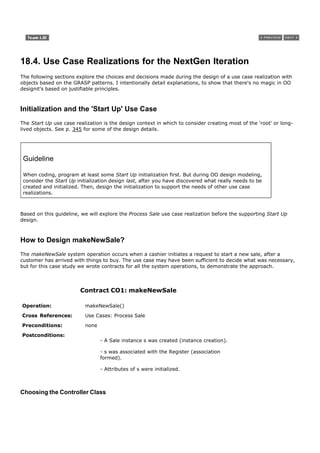

![(LRG). And by having the Register create the Sale, we can easily associate the Register with it over time so that
during future operations within the session, the Register will have a reference to the current Sale instance.
In addition to the above, when the Sale is created, it must create an empty collection (such as a Java List) to
record all the future SalesLineItem instances that will be added. This collection will be contained within and
maintained by the Sale instance, which implies by Creator that the Sale is a good candidate for creating the
collection.
Therefore, the Register creates the Sale, and the Sale creates an empty collection, represented by a multiobject
in the interaction diagram.
Hence, the interaction diagram in Figure 18.6 illustrates the design.
Figure 18.6. Sale and the collection creation.
[View full size image]
Conclusion
The design was not difficult, but the point of its careful explanation in terms of Controller and Creator was to
illustrate that the details of a design can be rationally and methodically decided and explained in terms of
principles and patterns, such as GRASP.
How to Design enterItem?
The enterItem system operation occurs when a cashier enters the itemID and (optionally) the quantity of
something to be purchased. Here is the complete contract:
Contract CO2: enterItem](https://image.slidesharecdn.com/softwaredevleopment-100607174022-phpapp01/85/Software-Development-442-320.jpg)

![Before considering how to achieve the lookup, we want to consider who should be responsible for it. Thus, a first
step is:
Start assigning responsibilities by clearly stating the responsibility.
To restate the problem:
Who should be responsible for knowing a ProductDescription, based on an itemID match?
This is neither a creation problem nor one of choosing a controller for a system event. Now we see our first
application of Information Expert in the design.
In many cases, the Expert pattern is the principal one to apply. Information Expert suggests that the object that
has the information required to fulfill the responsibility should do it. Who knows about all the ProductDescription
objects?
Analyzing the Domain Model reveals that the ProductCatalog logically contains all the ProductDescriptions. Once
again, taking inspiration from the domain, we design software classes with similar organization: a software
ProductCatalog will contain software ProductDescriptions.
With that decided, then by Information Expert ProductCatalog is a good candidate for this lookup responsibility
since it knows all the ProductDescription objects.
The lookup can be implemented, for example, with a method called getProductDescription (abbreviated as
getProductDesc in some of the diagrams).[2]
[2]
The name of access methods is idiomatic to each language. Java always uses the object.getFoo() form; C++ tends to use object.foo(); and C#
uses object.Foo, which hides (like Eiffel and Ada) whether access is by a method call or is direct access of a public attribute.
Visibility to a ProductCatalog
Who should send the getProductDescription message to the ProductCatalog to ask for a ProductDescription?
It is reasonable to assume that a long-life Register and a ProductCatalog instance were created during the initial
Start Up use case and that the Register object is permanently connected to the ProductCatalog object. With that
assumption (which we might record on a task list of things to ensure in the design when we get to designing the
initialization), we know that the Register can send the getProductDescription message to the ProductCatalog.
This implies another concept in object design: visibility. Visibility is the ability of one object to "see" or have a
reference to another object.
For an object to send a message to another object, it must have visibility to it.
Since we assume that the Register has a permanent connectionor referenceto the ProductCatalog, it has
visibility to it, and hence can send it messages such as getProductDescription. A following chapter explores the
question of visibility more closely.
The Final Design
Given the above discussion, the interaction diagram in Figure 18.7 and the DCD in Figure 18.8 (dynamic and](https://image.slidesharecdn.com/softwaredevleopment-100607174022-phpapp01/85/Software-Development-444-320.jpg)
![static views) reflects the decisions regarding the assignment of responsibilities and how objects should interact.
Mark the considerable reflection on the GRASP patterns, that brought us to this design; the design of object
interactions and responsibility assignment requires some deliberation.
Figure 18.7. The enterItem interaction diagram. Dynamic view.
[View full size image]
Figure 18.8. Partial DCD related to the enterItem design. Static view.
[View full size image]
Yet, once these principles are deeply "grasped" the decisions often come quickly, almost subconsciously.
Retrieving ProductDescriptions from a Database
In the final version of the NextGen POS application, it is unlikely that all the ProductDescriptions will be in
memory. They will most likely be stored in a relational database and retrieved on demand; some may be locally
cached for performance or fault-tolerance reasons. However, in the interest of simplicity, we defer for now the
issues surrounding retrieval from a database and assume that all the ProductDescriptions are in memory.
Chapter 38 explores the topic of database access of persistent objects, which is a larger topic influenced by the
choice of technologies, such as Java or .NET.](https://image.slidesharecdn.com/softwaredevleopment-100607174022-phpapp01/85/Software-Development-445-320.jpg)
![How to Design endSale?
The endSale system operation occurs when a cashier presses a button indicating the end of entering line items
into a sale (another name could have been endItemEntry). Here is the contract:
Contract CO3: endSale
Operation: endSale()
Cross References: Use Cases: Process Sale
Preconditions: There is an underway sale.
Postconditions: Sale.isComplete became true (attribute
modification).
Choosing the Controller Class
Our first choice involves handling the responsibility for the system operation message endSale. Based on the
Controller GRASP pattern, as for enterItem, we will continue to use Register as a controller.
Setting the Sale.isComplete Attribute
The contract postconditions state:
Sale.isComplete became true (attribute modification).
As always, Expert should be the first pattern considered unless the problem is a controller or creation problem
(which it is not).
Who should be responsible for setting the isComplete attribute of the Sale to true?
By Expert, it should be the Sale itself, since it owns and maintains the isComplete attribute. Thus, the Register
will send a becomeComplete message to the Sale to set it to true (see Figure 18.9).[3]
[3] That style is especially a Smalltalk idiom. Probably in Java, setComplete(true).
Figure 18.9. Completion of item entry.
[View full size image]
Calculating the Sale Total](https://image.slidesharecdn.com/softwaredevleopment-100607174022-phpapp01/85/Software-Development-446-320.jpg)

![For a Sale to calculate its total, it needs the subtotal for each SalesLineItem. Who should be responsible for
calculating the SalesLineItem subtotal? By Expert, it should be the SalesLineItem itself, since it knows the
quantity and the ProductDescription it is associated with. Therefore, SalesLineItem will have the
responsibility of knowing its subtotal, implemented as a getSubtotal method.
For the SalesLineItem to calculate its subtotal, it needs the price of the ProductDescription. Who should be
responsible for providing the ProductDescription price? By Expert, it should be the ProductDescription
itself, since it encapsulates the price as an attribute. Therefore, ProductDescription will have the
responsibility of knowing its price, implemented as a getPrice operation.
My goodness, that was detailed!
Although the above analysis is trivial in this case and the degree of excruciating elaboration
presented is uncalled for in actual design practice, the same reasoning strategy to find an Expert
can and should be applied in more difficult situations. If you follow the above logic, you can see
how to apply Expert to almost any problem.
The Sale.getTotal Design
Given the above discussion, let us construct an interaction diagram that illustrates what happens when a Sale is
sent a getTotal message. The first message in this diagram is getTotal, but observe that the getTotal message
is not a system operation message (such as enterItem or makeNewSale).
This leads to the following observation:
Not all interaction diagrams start with a system operation message; they can start with any
message for which the designer wishes to show interactions.
The interaction diagram is shown in Figure 18.10. First, the getTotal message is sent to a Sale instance. The
Sale then sends a getSubtotal message to each related SalesLineItem instance. The SalesLineItem in turn sends
a getPrice message to its associated ProductDescriptions.
Figure 18.10. Sale.getTotal interaction diagram.
[View full size image]](https://image.slidesharecdn.com/softwaredevleopment-100607174022-phpapp01/85/Software-Development-448-320.jpg)
![Since arithmetic is not (usually) illustrated via messages, we can illustrate the details of the calculations by
attaching algorithms or constraints to the diagram that defines the calculations.
Who will send the getTotal message to the Sale? Most likely, it will be an object in the UI layer, such as a Java
JFrame.
Observe in Figure 18.12 the use of the "method" note symbol style in UML 2.
Figure 18.12. Showing a method in a note symbol.
[View full size image]
Figure 18.11. Showing a method in a note symbol.
[View full size image]
How to Design makePayment?
The makePayment system operation occurs when a cashier enters the amount of cash tendered for payment.
Here is the complete contract:
Contract CO4: makePayment](https://image.slidesharecdn.com/softwaredevleopment-100607174022-phpapp01/85/Software-Development-449-320.jpg)

![lighterleading to a simpler Register definition. Also, the Register does not need to know about the existence of a
Payment instance because it can be recorded indirectly via the Saleleading to lower coupling in the Register.
This leads to the design shown in Figure 18.13.
Figure 18.13. Register.makePayment interaction diagram.
[View full size image]
This interaction diagram satisfies the postconditions of the contract: the Payment has been created, associated
with the Sale, and its amountTendered has been set.
Logging a Sale
Once complete, the requirements state that the sale should be placed in an historical log. As always,
Information Expert should be an early pattern considered unless the problem is a controller or creation problem
(which it is not), and the responsibility should be stated:
Who is responsible for knowing all the logged sales and doing the logging?
By the goal of low representational gap in the software design (in relation to our concepts of the domain), we
can reasonably expect a Store to know all the logged sales since they are strongly related to its finances. Other
alternatives include classic accounting concepts, such as a SalesLedger. Using a SalesLedger object makes sense
as the design grows and the Store becomes incohesive (see Figure 18.14).
Figure 18.14. Who should be responsible for knowing the completed sales?
[View full size image]](https://image.slidesharecdn.com/softwaredevleopment-100607174022-phpapp01/85/Software-Development-451-320.jpg)
![Note also that the postconditions of the contract indicate relating the Sale to the Store. This is an example of
postconditions not being what we want to actually achieve in the design. Perhaps we didn't think of a
SalesLedger earlier, but now that we have, we choose to use it instead of a Store. If this were the case, we
would (ideally) add SalesLedger to the Domain Model as well since a sales ledger is a concept in the real-world
domain. This kind of discovery and change during design work is to be expected.
In this case, we stick with the original plan of using the Store (see Figure 18.15).
Figure 18.15. Logging a completed sale.
[View full size image]
Calculating the Balance](https://image.slidesharecdn.com/softwaredevleopment-100607174022-phpapp01/85/Software-Development-452-320.jpg)
![The Process Sale use case implies that the balance due from a payment be printed on a receipt and displayed
somehow.
Because of the Model-View Separation principle, we should not concern ourselves with how the balance will be
displayed or printed, but we must ensure that it is known. Note that no class currently knows the balance, so we
need to create a design of object interactions that satisfies this requirement.
As always, Information Expert should be considered unless the problem is a controller or creation problem
(which it is not), and the responsibility should be stated:
Who is responsible for knowing the balance?
To calculate the balance, we need the sale total and payment cash tendered. Therefore, Sale and Payment are
partial Experts on solving this problem.
If the Payment is primarily responsible for knowing the balance, it needs visibility to the Sale, to ask the Sale
for its total. Since it does not currently know about the Sale, this approach would increase the overall coupling in
the designit would not support the Low Coupling pattern.
In contrast, if the Sale is primarily responsible for knowing the balance, it needs visibility to the Payment, to ask
it for its cash tendered. Since the Sale already has visibility to the Paymentas its creatorthis approach does not
increase the overall coupling and is therefore a preferable design.
Consequently, the interaction diagram in Figure 18.16 provides a solution for knowing the balance.
Figure 18.16. Sale.getBalance interaction diagram.
[View full size image]
The Final NextGen DCD for Iteration-1
In accordance with the design decisions in this chapter, Figure 18.17 illustrates a static-view DCD of the
emerging design for the domain layer, reflecting the use case realizations for the chosen scenarios of Process
Sale in iteration-1.
Figure 18.17. A more complete DCD reflecting most design decisions.
[View full size image]](https://image.slidesharecdn.com/softwaredevleopment-100607174022-phpapp01/85/Software-Development-453-320.jpg)
![Of course, we still have more OO design workeither while coding or while modelingto do in other layers, include
the UI layer and services layers.
How to Connect the UI Layer to the Domain Layer?
Common designs by which objects in the UI layer obtain visibility to objects in the domain layer include the
following:
An initializer object (for example, a Factory object) called from the application starting method (e.g., the
Java main method) creates both a UI and a domain object and passes the domain object to the UI.
A UI object retrieves the domain object from a well-known source, such as a factory object that is
responsible for creating domain objects.
Once the UI object has a connection to the Register instance (the facade controller in this design), it can forward
system event messages, such as the enterItem and endSale message, to it (see Figure 18.18).
Figure 18.18. Connecting the UI and domain layers.
[View full size image]](https://image.slidesharecdn.com/softwaredevleopment-100607174022-phpapp01/85/Software-Development-454-320.jpg)
![In the case of the enterItem message, we want the window to show the running total after each entry. Design
solutions are:
Add a getTotal method to the Register. The UI sends the getTotal message to the Register, which
delegates to the Sale. This has the possible advantage of maintaining lower coupling from the UI to the
domain layerthe UI only knows of the Register object. But it starts to expand the interface of the Register
object, making it less cohesive.
A UI asks for a reference to the current Sale object, and then when it requires the total (or any other
information related to the sale), it directly sends messages to the Sale. This design increases the coupling
from the UI to the domain layer. However, as we explored in the Low Coupling GRASP pattern discussion,
higher coupling in and of itself is not a problem; rather, coupling to unstable things is a real problem.
Assume we decide the Sale is a stable object that will be an integral part of the designwhich is reasonable.
Then, coupling to the Sale is not a major problem.
As illustrated in Figure 18.19, this design follows the second approach.
Figure 18.19. Connecting the UI and domain layers.
[View full size image]](https://image.slidesharecdn.com/softwaredevleopment-100607174022-phpapp01/85/Software-Development-455-320.jpg)

![In a Java application, for example, the main method may create the initial domain object or delegate the work
to a Factory object that creates it.
public class Main
{
public static void main( String[] args )
{
// Store is the initial domain object.
// The Store creates some other domain objects.
Store store = new Store();
Register register = store.getRegister();
ProcessSaleJFrame frame = new ProcessSaleJFrame( register );
...
}
}
Choosing the Initial Domain Object
What should the class of the initial domain object be?
Guideline
Choose as an initial domain object a class at or near the root of the containment or aggregation
hierarchy of domain objects. This may be a facade controller, such as Register, or some other
object considered to contain all or most other objects, such as a Store.
High Cohesion and Low Coupling considerations influence the choice between these alternatives. In this
application, we chose the Store as the initial object.
Store.create Design
The tasks of creation and initialization derive from the needs of the prior design work, such as the design for
handling enterItem and so on. By reflecting on the prior interaction designs, we identify the following
initialization work:
Create a Store, Register, ProductCatalog, and ProductDescriptions.
Associate the ProductCatalog with ProductDescriptions.
Associate Store with ProductCatalog.
Associate Store with Register.
Associate Register with ProductCatalog.
Figure 18.20 shows the design. We chose the Store to create the ProductCatalog and Register by the Creator](https://image.slidesharecdn.com/softwaredevleopment-100607174022-phpapp01/85/Software-Development-457-320.jpg)
![pattern. Likewise, we chose ProductCatalog to create the ProductDescriptions. Recall that this approach to
creating the specifications is temporary. In the final design, we will materialize them from a database, as
needed.
Figure 18.20. Creation of the initial domain object and subsequent objects.
[View full size image]
Applying UML: Observe that the creation of all the ProductDescription instances and their addition to a
container happens in a repeating section, indicated by the * following the sequence numbers.
An interesting deviation between modeling the real-world domain and the design is illustrated in the fact that
the software Store object only creates one Register object. A real store may house many real registers or POS
terminals. However, we are considering a software design, not real life. In our current requirements, our
software Store only needs to create a single instance of a software Register.
Multiplicity between classes of objects in the Domain Model and Design Model may not be the
same.](https://image.slidesharecdn.com/softwaredevleopment-100607174022-phpapp01/85/Software-Development-458-320.jpg)


![the player has enough money or if its color fits in with the player's "color strategy." What object would be
expected to know a player's cash total? Answer: a Player (by LRG). What object would be expected to know a
player's color strategy? Answer: a Player (by LRG, as it involves a player's current holdings of properties).
Thus, in the end, by these guidelines Player turns out to be a good candidate, justified by Expert when we
consider the full game rules.
My goodness, that was detailed!
Surely this discussion was more detailed than you normally want to read! Yet, if you can now
follow its reasoning and apply it in new situations, it will serve you very well for the remainder of
your career as an OO developer, and thus have been worth the effort.
Based on the above, Figure 18.24 illustrates the emerging dynamic design and static design.
Figure 18.24. Player takes a turn by Expert.
[View full size image]
Applying UML: Notice the approach to indicating that the takeTurn message is sent to each player in a
collection named players.
Taking a Turn
Taking a turn means:
1. calculating a random number total between 2 and 12 (the range of two dice)
2.
3.](https://image.slidesharecdn.com/softwaredevleopment-100607174022-phpapp01/85/Software-Development-463-320.jpg)
![1.
2. calculating the new square location
3. moving the player's piece from an old location to a new square location
First, the random number problem: By LRG, we'll create a Die object with a faceValue attribute. Calculating a
new random faceValue involves changing information in the Die, so by Expert Die should be able to "roll" itself
(generate a new random value, using domain vocabulary), and answer its faceValue.
Second, the new square location problem: By LRG, it's reasonable that a Board knows all its Squares. Then by
Expert a Board will be responsible for knowing a new square location, given an old square location, and some
offset (the dice total).
Third, the piece movement problem: By LRG, it's reasonable for a Player to know its Piece, and a Piece its
Square location (or even for a Player to directly know its Square location). Then by Expert a Piece will set its
new location, but it may receive that new location from its owner, the Player.
Who Coordinates All This?
The above three steps need to be coordinated by some object. Since the Player is responsible for taking a turn,
the Player should coordinate.
The Problem of Visibility
However, that the Player coordinates these steps implies its collaboration with the Die, Board, and Piece objects.
And this implies a visibility needthe Player must have an object reference to those objects.
Since the Player will need visibility to the Die, Board, and Piece objects each and every turn, we can usefully
initialize the Player during startup with permanent references to those objects.
The Final Design of playGame
Based on the above design decisions, the emerging dynamic design is as shown in Figure 18.25 and the static
design as in Figure 18.26. Notice that each message, each allocation of responsibility, was methodically and
rationally motivated by the GRASP principles. As you come to master these principles, you will be able to reason
through a design and evaluate existing ones in terms of coupling, cohesion, Expert, and so forth.
Figure 18.25. Dynamic design for playGame.
[View full size image]](https://image.slidesharecdn.com/softwaredevleopment-100607174022-phpapp01/85/Software-Development-464-320.jpg)
![Figure 18.26. Static design for playGame.
[View full size image]
Applying UML:
Notice in Figure 18.25 that I show two sequence diagrams. In the top, the takeTurn message to a Player is
not expanded. Then, in the bottom diagram, I expand the takeTurn message. This is a common sketching
style, so that each wall diagram is not too large. The two diagrams are related informally. More formally, I
could use UML sd and ref frames (see p. 235), which would be easy and appropriate in a UML tool; but for](https://image.slidesharecdn.com/softwaredevleopment-100607174022-phpapp01/85/Software-Development-465-320.jpg)
![wall sketching, informality suffices.
Notice again, with the roll and getFaceValue messages to a Die object, the convention of drawing a loop
frame around messages to a collection selection object, to indicate collection over each element in a
collection.
Notice the parameter fvTot in the getSquare message. I am informally suggesting this is the total of all the
Die faceValues. This kind of informality is appropriate when we apply "UML as sketch," assuming the
audience understands the context.
The Command-Query Separation Principle
Notice in Figure 18.25 that the message to roll the Die is followed by a second getFaceValue to retrieve its new
faceValue. In particular, the roll method is voidit has no return value. For example:
// style #1; used in the official solution
public void roll()
{
faceValue = // random num generation
}
public int getFaceValue()
{
return faceValue;
}
Why not make roll non-void and combine these two functions so that the roll method returns the new faceValue,
as follows?
// style #2; why is this poor?
public int roll()
{
faceValue = // random num generation
return faceValue;
}
You can find many examples of code that follow style #2, but it is considered undesirable because it violates the
Command-Query Separation Principle, (CQS) a classic OO design principle for methods [Meyer88]. This
principle states that every method should either be:
a command method that performs an action (updating, coordinating, …), often has side effects such as
changing the state of objects, and is void (no return value); or
a query that returns data to the caller and has no side effectsit should not permanently change the state of
any objects
Butand this is the key pointa method should not be both.
The roll method is a commandit has the side effect of changing the state of the Die's faceValue. Therefore, it
should not also return the new faceValue, as then the method also becomes a kind of query and violates the
"must be void" rule.](https://image.slidesharecdn.com/softwaredevleopment-100607174022-phpapp01/85/Software-Development-466-320.jpg)

![18.6. Process: Iterative and Evolutionary Object Design
I've made many suggestions about iterative and evolutionary object design for use case realizations over the
last few chapters, including
"On to Object Design" on page 213
"Object Design: Example Inputs, Activities, and Outputs" on page 272
The essential point: Keep it light and short, move quickly to code and test, and don't try to detail everything in
UML models. Model the creative, difficult parts of the design.
Figure 18.28 offers suggestions on the time and space for doing this work.
Figure 18.28. Sample process and setting context.
[View full size image]
Object Design Within the UP
To again consider the UP as the example iterative method: use case realizations are part of the UP Design
Model.
Inception The Design Model and use case realizations will not usually be started until elaboration because they
involve detailed design decisions, which are premature during inception.](https://image.slidesharecdn.com/softwaredevleopment-100607174022-phpapp01/85/Software-Development-469-320.jpg)


![Introduction
Visibility is the ability of one object to see or have reference to another. This chapter explores this basic but
necessary design issue; those new to object design sometimes don't think about and design to achieve
necessary visibility.
[View full size image]](https://image.slidesharecdn.com/softwaredevleopment-100607174022-phpapp01/85/Software-Development-473-320.jpg)
![19.1. Visibility Between Objects
The designs created for the system operations (enterItem, and so on) illustrate messages between objects. For
a sender object to send a message to a receiver object, the sender must be visible to the receiverthe sender
must have some kind of reference or pointer to the receiver object.
For example, the getProductDescription message sent from a Register to a ProductCatalog implies that the
ProductCatalog instance is visible to the Register instance, as shown in Figure 19.1.
Figure 19.1. Visibility from the Register to ProductCatalog is required.[1]
[1] In this and subsequent code examples, language simplifications may be made for the sake of brevity and clarity.
When creating a design of interacting objects, it is necessary to ensure that the necessary visibility is present to
support message interaction.](https://image.slidesharecdn.com/softwaredevleopment-100607174022-phpapp01/85/Software-Development-474-320.jpg)
![19.2. What is Visibility?
In common usage, visibility is the ability of an object to "see" or have a reference to another object. More
generally, it is related to the issue of scope: Is one resource (such as an instance) within the scope of another?
There are four common ways that visibility can be achieved from object A to object B:
Attribute visibility B is an attribute of A.
Parameter visibility B is a parameter of a method of A.
Local visibility B is a (non-parameter) local object in a method of A.
Global visibility B is in some way globally visible.
The motivation to consider visibility is this:
For an object A to send a message to an object B, B must be visible to A.
For example, to create an interaction diagram in which a message is sent from a Register instance to a
ProductCatalog instance, the Register must have visibility to the ProductCatalog. A typical visibility solution is
that a reference to the ProductCatalog instance is maintained as an attribute of the Register.
Attribute Visibility
Attribute visibility from A to B exists when B is an attribute of A. It is a relatively permanent visibility because
it persists as long as A and B exist. This is a very common form of visibility in object-oriented systems.
To illustrate, in a Java class definition for Register, a Register instance may have attribute visibility to a
ProductCatalog, since it is an attribute (Java instance variable) of the Register.
public class Register
{
...
private ProductCatalog catalog;
...
}
This visibility is required because in the enterItem diagram shown in Figure 19.2, a Register needs to send the
getProductDescription message to a ProductCatalog:
Figure 19.2. Attribute visibility.
[View full size image]](https://image.slidesharecdn.com/softwaredevleopment-100607174022-phpapp01/85/Software-Development-475-320.jpg)
![Parameter Visibility
Parameter visibility from A to B exists when B is passed as a parameter to a method of A. It is a relatively
temporary visibility because it persists only within the scope of the method. After attribute visibility, it is the
second most common form of visibility in object-oriented systems.
To illustrate, when the makeLineItem message is sent to a Sale instance, a ProductDescription instance is
passed as a parameter. Within the scope of the makeLineItem method, the Sale has parameter visibility to a
ProductDescription (see Figure 19.3).
Figure 19.3. Parameter visibility.
[View full size image]
It is common to transform parameter visibility into attribute visibility. When the Sale creates a new
SalesLineItem, it passes the ProductDescription in to its initializing method (in C++ or Java, this would be its
constructor). Within the initializing method, the parameter is assigned to an attribute, thus establishing
attribute visibility (Figure 19.4).
Figure 19.4. Parameter to attribute visibility.
[View full size image]](https://image.slidesharecdn.com/softwaredevleopment-100607174022-phpapp01/85/Software-Development-476-320.jpg)

![// there is implicit local visibility to the foo object
// returned via the getFoo call
anObject.getFoo().doBar();
Global Visibility
Global visibility from A to B exists when B is global to A. It is a relatively permanent visibility because it
persists as long as A and B exist. It is the least common form of visibility in object-oriented systems.
One way to achieve global visibility is to assign an instance to a global variable, which is possible in some
languages, such as C++, but not others, such as Java.
The preferred method to achieve global visibility is to use the Singleton pattern [GHJV95], which is discussed
in a later chapter.](https://image.slidesharecdn.com/softwaredevleopment-100607174022-phpapp01/85/Software-Development-478-320.jpg)

![Introduction
With the completion of interaction diagrams and DCDs for the current iteration of the case studies, there's more
than enough thought and detail to cut some code for the domain layer of objects.
The UML artifacts created during the design workthe interaction diagrams and DCDswill be used as input to the
code generation process.
In UP terms, there exists an Implementation Model. This is all the implementation artifacts, such as the
source code, database definitions, JSP/XML/HTML pages, and so forth. Thus, the code being created in this
chapter can be considered part of the UP Implementation Model.
[View full size image]
Language Samples
Java is used for the examples because of its widespread use and familiarity. However, this is not meant to imply
a special endorsement of Java; C#, Visual Basic, C++, Smalltalk, Python, and many more languages are
amenable to the object design principles and mapping to code presented in this case study.](https://image.slidesharecdn.com/softwaredevleopment-100607174022-phpapp01/85/Software-Development-480-320.jpg)


![20.3. Creating Class Definitions from DCDs
At the very least, DCDs depict the class or interface name, superclasses, operation signatures, and attributes of
a class. This is sufficient to create a basic class definition in an OO language. If the DCD was drawn in a UML
tool, it can generate the basic class definition from the diagrams.
Defining a Class with Method Signatures and Attributes
From the DCD, a mapping to the attribute definitions (Java fields) and method signatures for the Java definition
of SalesLineItem is straightforward, as shown in Figure 20.1.
Figure 20.1. SalesLineItem in Java.
[View full size image]
Note the addition in the source code of the Java constructor SalesLineItem(…). It is derived from the
create(desc, qty) message sent to a SalesLineItem in the enterItem interaction diagram. This indicates, in Java,
that a constructor supporting these parameters is required. The create method is often excluded from the class
diagram because of its commonality and multiple interpretations, depending on the target language.](https://image.slidesharecdn.com/softwaredevleopment-100607174022-phpapp01/85/Software-Development-483-320.jpg)
![20.4. Creating Methods from Interaction Diagrams
The sequence of the messages in an interaction diagram translates to a series of statements in the method
definitions. The enterItem interaction diagram in Figure 20.2 illustrates the Java definition of the enterItem
method. For this example, we will explore the implementation of the Register and its enterItem method. A Java
definition of the Register class is shown in Figure 20.3.
Figure 20.2. The enterItem interaction diagram.
[View full size image]
The enterItem message is sent to a Register instance; therefore, the enterItem method is defined in class
Register.
public void enterItem(ItemID itemID, int qty)
Message 1: A getProductDescription message is sent to the ProductCatalog to retrieve a ProductDescription.
ProductDescription desc = catalog.getProductDescription(itemID);
Message 2: The makeLineItem message is sent to the Sale.
currentSale.makeLineItem(desc, qty);
In summary, each sequenced message within a method, as shown on the interaction diagram, is mapped to a
statement in the Java method.
The complete enterItem method and its relationship to the interaction diagram is shown in Figure 20.4.](https://image.slidesharecdn.com/softwaredevleopment-100607174022-phpapp01/85/Software-Development-484-320.jpg)
![The Register.enterItem Method
Figure 20.3. The Register class.
[View full size image]
Figure 20.4. The enterItem method.
[View full size image]](https://image.slidesharecdn.com/softwaredevleopment-100607174022-phpapp01/85/Software-Development-485-320.jpg)
![20.5. Collection Classes in Code
One-to-many relationships are common. For example, a Sale must maintain visibility to a group of many
SalesLineItem instances, as shown in Figure 20.5. In OO programming languages, these relationships are
usually implemented with the introduction of a collection object, such as a List or Map, or even a simple array.
Figure 20.5. Adding a collection.
[View full size image]
For example, the Java libraries contain collection classes such as ArrayList and HashMap, which implement the
List and Map interfaces, respectively. Using ArrayList, the Sale class can define an attribute that maintains an
ordered list of SalesLineItem instances.
The choice of collection class is of course influenced by the requirements; key-based lookup requires the use of
a Map, a growing ordered list requires a List, and so on.
As a small point, note that the lineItems attribute is declared in terms of its interface.
Guideline: If an object implements an interface, declare the variable in terms of the interface, not the concrete
class.
For example, in Figure 20.5 the definition for the lineItems attribute demonstrates this guideline:
private List lineItems = new ArrayList();](https://image.slidesharecdn.com/softwaredevleopment-100607174022-phpapp01/85/Software-Development-486-320.jpg)

![20.7. Defining the Sale.makeLineItem Method
As a final example, the makeLineItem method of class Sale can also be written by inspecting the enterItem
collaboration diagram. An abridged version of the interaction diagram, with the accompanying Java method, is
shown in Figure 20.6.
Figure 20.6. Sale.makeLineItem method.
[View full size image]](https://image.slidesharecdn.com/softwaredevleopment-100607174022-phpapp01/85/Software-Development-488-320.jpg)
![20.8. Order of Implementation
Classes need to be implemented (and ideally, fully unit tested) from least-coupled to most-coupled (see Figure
20.7). For example, possible first classes to implement are either Payment or ProductDescription; next are
classes only dependent on the prior implementationsProductCatalog or SalesLineItem.
Figure 20.7. Possible order of class implementation and testing.
[View full size image]](https://image.slidesharecdn.com/softwaredevleopment-100607174022-phpapp01/85/Software-Development-489-320.jpg)
![20.9. Test-Driven or Test-First Development
An excellent practice promoted by the Extreme Programming (XP) method [Beck00], and applicable to the UP
and other iterative methods (as most XP practices are), is test-driven development (TDD) or test-first
development. In this practice, unit testing code is written before the code to be tested, and the developer
writes unit testing code for all production code. The basic rhythm is to write a little test code, then write a little
production code, make it pass the test, then write some more test code, and so forth. This is explore in more
detail in a following chapter.
TDD p. 386](https://image.slidesharecdn.com/softwaredevleopment-100607174022-phpapp01/85/Software-Development-490-320.jpg)


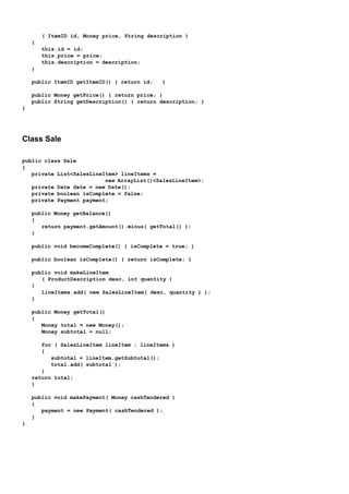

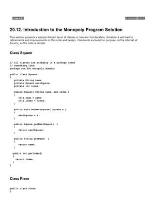

![public Square getSquare(Square start, int distance)
{
int endIndex = (start.getIndex() + distance) % SIZE;
return (Square) squares.get(endIndex);
}
public Square getStartSquare()
{
return (Square) squares.get(0);
}
private void buildSquares()
{
for (int i = 1; i <= SIZE; i++)
{
build(i);
}
}
private void build(int i)
{
Square s = new Square("Square " + i, i - 1);
squares.add(s);
}
private void linkSquares()
{
for (int i = 0; i < (SIZE - 1); i++)
{
link(i);
}
Square first = (Square) squares.get(0);
Square last = (Square) squares.get(SIZE - 1);
last.setNextSquare(first);
}
private void link(int i)
{
Square current = (Square) squares.get(i);
Square next = (Square) squares.get(i + 1);
current.setNextSquare(next);
}
}
Class Player
public class Player
{
private String name;
private Piece piece;
private Board board;
private Die[] dice;
public Player(String name, Die[] dice, Board board)
{
this.name = name;](https://image.slidesharecdn.com/softwaredevleopment-100607174022-phpapp01/85/Software-Development-498-320.jpg)
![this.dice = dice;
this.board = board;
piece = new Piece(board.getStartSquare());
}
public void takeTurn()
{
// roll dice
int rollTotal = 0;
for (int i = 0; i < dice.length; i++)
{
dice[i].roll();
rollTotal += dice[i].getFaceValue();
}
Square newLoc = board.getSquare(piece.getLocation(), rollTotal);
piece.setLocation(newLoc);
}
public Square getLocation()
{
return piece.getLocation();
}
public String getName()
{
return name;
}
}
Class MonopolyGame
public class MonopolyGame
{
private static final int ROUNDS_TOTAL = 20;
private static final int PLAYERS_TOTAL = 2;
private List players = new ArrayList( PLAYERS_TOTAL );
private Board board = new Board( );
private Die[] dice = { new Die(), new Die() };
public MonopolyGame( )
{
Player p;
p = new Player( "Horse", dice, board );
players.add( p );
p = new Player( "Car", dice, board );
players.add( p );
}
public void playGame( )
{
for ( int i = 0; i < ROUNDS_TOTAL; i++ )
{
playRound();
}
}](https://image.slidesharecdn.com/softwaredevleopment-100607174022-phpapp01/85/Software-Development-499-320.jpg)


![Introduction
Extreme Programming (XP) promoted an important testing practice: writing the tests first. It also promoted
continuously refactoring code to improve its qualityless duplication, increased clarity, and so forth. Modern tools
support both practices, and many OO developers swear by their value.
[View full size image]](https://image.slidesharecdn.com/softwaredevleopment-100607174022-phpapp01/85/Software-Development-502-320.jpg)
![21.1. Test-Driven Development
An excellent practice promoted by the iterative and agile XP method [Beck00], and applicable to the UP (as
most XP practices are), is test-driven development (TDD) [Beck00]. It is also known as test-first
development. TDD covers more than just unit testing (testing individual components), but this introduction
will focus on its application to unit testing individual classes.
In OO unit testing TDD-style, test code is written before the class to be tested, and the developer writes unit
testing code for nearly all production code.
The basic rhythm is to write a little test code, then write a little production code, make it pass the test, then
write some more test code, and so forth.
Key Point: The test is written first, imagining the code to be tested is written.
Advantages include:
The unit tests actually get written Human (or at least programmer) nature is such that avoidance of
writing unit tests is very common, if left as an afterthought.
Programmer satisfaction leading to more consistent test writing This is more important than it
sounds for sustainable, enjoyable testing work. If, following the traditional style, a developer first writes
the production code, informally debugs it, and then as an afterthought is expected to add unit tests, it
doesn't feel satisfying. This is test-last development, also known as Just-this-one-time-I'll-skip-writing-
the-test development. It's human psychology. However, if the test is written first, we feel a worthwhile
challenge and question in front of us: Can I write code to pass this test? And then, after the code is cut to
pass the tests, there is some feeling of accomplishmentmeeting a goal. And a very useful goalan
executable, repeatable test. The psychological aspects of development can't be ignoredprogramming is a
human endeavor.
Clarification of detailed interface and behavior This sounds subtle, but it turns out in practice to be a
major value of TDD. Consider your state of mind if you write the test for an object first: As you write the
test code, you must imagine that the object code exists. For example, if in your test code you write
sale.makeLineItem(description, 3) to test the makeLineItem method (which doesn't exist yet), you must
think through the details of the public view of the methodits name, return value, parameters, and
behavior. That reflection improves or clarifies the detailed design.
Provable, repeatable, automated verification Obviously, having hundreds or thousands of unit tests
that build up over the weeks provides some meaningful verification of correctness. And because they can
be run automatically, it's easy. Over time, as the test base builds from 10 tests to 50 tests to 500 tests,
the early, more painful investment in writing tests starts to really feel like it's paying off as the size of the
application grows.
The confidence to change things In TDD, there will eventually be hundreds or thousands of unit tests,
and a unit test class for each production class. When a developer needs to change existing codewritten by
themselves or othersthere is a unit test suite that can be run[1] , providing immediate feedback if the
change caused an error.
[1] A popular free open source tool to automatically re-build the application and run all unit tests is CruiseControl. Find it on the Web.
The most popular unit testing framework is the xUnit family (for many languages), available at
www.junit.org.[2] For Java, the popular version is JUnit. There's also an NUnit for .NET, and so forth. JUnit is
integrated into most of the popular Java IDEs, such as Eclipse (www.eclipse.org).
[2]
The xUnit family, and JUnit, was started by Kent Beck (creator of XP) and Eric Gamma (one of the Gang-of-Four design pattern authors, and the
chief architect of the popular Eclipse IDE).](https://image.slidesharecdn.com/softwaredevleopment-100607174022-phpapp01/85/Software-Development-503-320.jpg)

![// STEP 2: EXECUTE THE METHOD TO TEST
// NOTE: We write this code **imagining** there
// is a makeLineItem method. This act of imagination
// as we write the test tends to improve or clarify
// our understanding of the detailed interface to
// to the object. Thus TDD has the side-benefit of
// clarifying the detailed object design.
// test makeLineItem
sale.makeLineItem( desc, 1 );
sale.makeLineItem( desc, 2 );
// STEP 3: EVALUATE THE RESULTS
// there could be many assertTrue statements
// for a complex evaluation
// verify the total is 7.5
assertTrue( sale.getTotal().equals( total ));
}
}
Only after this testMakeLineItem test method is written do we then write the Sale.makeLineItem method to
pass this test. Hence, the term test-driven or test-first development.
IDE Support for TDD and xUnit
Most IDEs have built-in support for some xUnit tool. For example, Eclipse supports JUnit. JUnit includes a visual
cueif all the tests pass when executed, it displays a green bar. This gave rise to the TDD mantra: Keep the bar
green to keep the code clean. Figure 21.1 illustrates.
Figure 21.1. Support for TDD and JUnit in a popular IDE, Eclipse.
[View full size image]](https://image.slidesharecdn.com/softwaredevleopment-100607174022-phpapp01/85/Software-Development-505-320.jpg)

![21.2. Refactoring
Refactoring [Fowler99] is a structured, disciplined method to rewrite or restructure existing code without
changing its external behavior, applying small transformation steps combined with re-executing tests each step.
Continuously refactoring code is another XP practice and applicable to all iterative methods (including the UP).[3]
[3]
Ralph Johnson (one of the Gang-of-Four design pattern authors) and Bill Opdyke first discussed refactoring in 1990. Kent Beck (XP creator),
along with Martin Fowler, are two other refactoring pioneers.
The essence of refactoring is applying small behavior preserving transformations (each called a 'refactoring'),
one at a time. After each transformation, the unit tests are re-executed to prove that the refactoring did not
cause a regression (failure). Therefore, there's a relationship between refactoring and TDDall those unit tests
support the refactoring process.
Each refactoring is small, but a series of transformationseach followed by executing the unit tests againcan, of
course, produce a major restructuring of the code and design (for the better), all the while ensuring the
behavior remains the same.
What are the activities and goals refactoring? They are simply the activities and goals of good programming:
remove duplicate code
improve clarity
make long methods shorter
remove the use of hard-coded literal constants
and more…
Code that's been well-refactored is short, tight, clear, and without duplicationit looks like the work of a master
programmer. Code that doesn't have these qualities smells bad or has code smells. In other words, there is a
poor design. Code smells is a metaphor in refactoringthey are hints that something may be wrong in the code.
The name code smell was chosen to suggest that when we look into the smelly code, it might turn out to be
alright and not need improvement. That's in contrast to code stenchtruly putrid code crying out for clean up!
Some code smells include:
duplicated code
big method
class with many instance variables
class with lots of code
strikingly similar subclasses
little or no use of interfaces in the design
high coupling between many objects
and so many other ways bad code is written…[4]
[4]
See the original and major OO, patterns, XP, and refactoring Wiki c2.com/cgi/wiki for many Wiki pages on code smells and refactoring.
Fascinating site…
The remedy to smelly code are the refactorings. Like patterns, refactorings have names, such as Extract
Method. There are about 100 named refactorings; here's a sample to get a sense of them:](https://image.slidesharecdn.com/softwaredevleopment-100607174022-phpapp01/85/Software-Development-507-320.jpg)
![Refactoring Description
Extract Method Transform a long method into a shorter one by factoring out a
portion into a private helper method.
Extract Constant Replace a literal constant with a constant variable.
Introduce Explaining Variable Put the result of the expression, or parts of the expression, in a
(specialization of Extract Local Variable) temporary variable with a name that explains the purpose.
Replace Constructor Call with Factory In Java, for example, replace using the new operator and
Method constructor call with invoking a helper method that creates the
object (hiding the details).
Example
This example demonstrates the common Extract Method refactoring. Notice in the Figure 21.2 listing that the
takeTurn method in the Player class has an initial section of code that rolls the dice and calculates the total in a
loop. This code is itself a distinct, cohesive unit of behavior; we can make the takeTurn method shorter, clearer,
and better supporting High Cohesion by extracting that code into a private helper method called rollDice. Notice
that the rollTotal value is required in takeTurn, so this helper method must return the rollTotal.[5]
[5] That violates the Command-Query Separation Principle (p. 358), but the principle is more easily relaxed for private methods. It is a guideline, not
a rule.
Figure 21.2. The takeTurn method before refactoring.
public class Player
{
private Piece piece;
private Board board;
private Die[] dice;
// …
public void takeTurn()
{
// roll dice
int rollTotal = 0;
for (int i = 0; i < dice.length; i++)
{
dice[i].roll();
rollTotal += dice[i].getFaceValue();
}
Square newLoc = board.getSquare(piece.getLocation(), rollTotal);
piece.setLocation(newLoc);
}
} // end of class
Now here's the code after applying the Extract Method refactoring:
Figure 21.3. The code after refactoring with Extract Method.](https://image.slidesharecdn.com/softwaredevleopment-100607174022-phpapp01/85/Software-Development-508-320.jpg)
![public class Player
{
private Piece piece;
private Board board;
private Die[] dice;
// …
public void takeTurn()
{
// the refactored helper method
int rollTotal = rollDice();
Square newLoc = board.getSquare(piece.getLocation(), rollTotal);
piece.setLocation(newLoc);
}
private int rollDice()
{
int rollTotal = 0;
for (int i = 0; i < dice.length; i++)
{
dice[i].roll();
rollTotal += dice[i].getFaceValue();
}
return rollTotal;
}
} // end of class
We will see in iteration-2 that this rollDice helper method is not a great solutionthe Pure Fabrication pattern will
suggest an alternative that also preserves the Command-Query Separation Principlebut it suffices to illustrate
the refactoring operation.
As a second short example, one of my favorite simple refactorings is Introduce Explaining Variable because it
clarifies, simplifies, and reduces the need for comments. The listings in Figure 21.4 and Figure 21.5 illustrate.
Figure 21.4. Before introducing an explaining variable.
// good method name, but the logic of the body is not clear
boolean isLeapYear( int year )
{
return( ( ( year % 400 ) == 0 ) ||
( ( ( year % 4 ) == 0 ) && ( ( year % 100 ) != 0 ) ) );
}
Figure 21.5. After introducing an explaining variable.
// that's better!
boolean isLeapYear( int year )
{
boolean isFourthYear = ( ( year % 4 ) == 0 );
boolean isHundrethYear = ( ( year % 100 ) == 0);
boolean is4HundrethYear = ( ( year % 400 ) == 0);](https://image.slidesharecdn.com/softwaredevleopment-100607174022-phpapp01/85/Software-Development-509-320.jpg)
![return (
is4HundrethYear
|| ( isFourthYear && ! isHundrethYear ) );
}
IDE Support for Refactoring
Most of the dominant IDEs include automated refactoring support. See Figure 21.6 and Figure 21.7 for an
example in the Eclipse IDE of applying the Extract Method refactoring. The rollDice method is automatically
generated, as is the call to it from the takeTurn method. Notice that the tool is smart enough to see the need to
return the rollTotal variable. Nice!
Figure 21.6. IDE before refactoring.
[View full size image]
Figure 21.7. IDE after refactoring.](https://image.slidesharecdn.com/softwaredevleopment-100607174022-phpapp01/85/Software-Development-510-320.jpg)


![23.1. Case Study: NextGen POS
Use Cases
No refinement is needed for the use cases this iteration.
However, at a process level I recommend (as does the UP) a second short one- or two-day requirements
workshop this iteration (near the end of iteration-1 and again near the end of iteration-2), within which more
requirements will be investigated and written in detail. The previously fully analyzed use cases (for example,
Process Sale) will be revisited and probably refined based on insights gained from iteration-1 programming and
tests. In iterative methods, note the interplay of early programming and testing with parallel requirements
analysis that is improved by feedback from early development.
SSDs
This iteration includes adding support for third-party external systems with varying interfaces, such as a tax
calculator. The NextGen POS system will be remotely communicating with external systems. Consequently, the
SSDs should be updated to reflect at least some of the inter-system collaborations, in order to clarify what the
new system-level events are.
Figure 23.1 illustrates an SSD for one scenario of paying by credit, which requires collaboration with several
external systems. Even though the design of paying by credit is not handled in this iteration, the modeler (me)
has drawn an SSD based on it (and probably several others as well), to better understand the inter-system
collaboration, and thus the required support for varying interfaces in the external systems.
Figure 23.1. An SSD scenario that illustrates some external systems.
[View full size image]](https://image.slidesharecdn.com/softwaredevleopment-100607174022-phpapp01/85/Software-Development-523-320.jpg)

![23.2. Case Study: Monopoly
Use Cases, etc.
Uses case were skipped, as most know the rules of the game. No update to the SSD is required, and no
operations contracts were written.
Domain Model
The concepts Square, GoSquare, IncomeTaxSquare, and GoToJailSquare are all similarthey are variations on a
square. In this situation, it is possible (and often useful) to organize them into a generalization-
specialization class hierarchy (or simply class hierarchy) in which the superclass Square represents a
more general concept and the subclasses more specialized ones.
In the UML, generalization-specialization relationships are shown with a large triangular arrow pointing from the
specialization class to the more general class, as shown in Figure 23.2.
Figure 23.2. Monopoly domain model changes for iteration-2.
[View full size image]
Generalization is the activity of identifying commonality among concepts and defining superclass (general
concept) and subclass (specialized concept) relationships. It is a way to construct taxonomic classifications
among concepts that are then illustrated in class hierarchies.
The subject of generalization and specialization is covered more thoroughly in a later chapter. See
"Generalization" on page 509.
Identifying a superclass and subclasses is of value in a domain model because their presence allows us to
understand concepts in more general, refined and abstract terms. It leads to economy of expression, improved
comprehension and a reduction in repeated information.
When to show subclasses? The following are common motivations:](https://image.slidesharecdn.com/softwaredevleopment-100607174022-phpapp01/85/Software-Development-525-320.jpg)
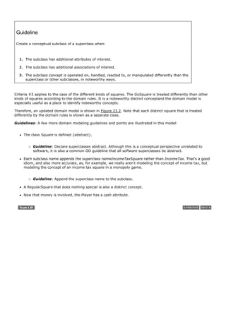

![Introduction
The inception phase chapters and those for iteration-1 in the elaboration phase emphasized a wide range of
fundamental analysis and object design skills, in order to share information on a breadth of common steps in
building object systems.
In this iteration, the case study just emphasizes:
essential object design
the use of patterns to create a solid design
applying the UML to visualize the models
These are primary objectives of the book, and critical skills.
[View full size image]
There is minimal discussion of requirements analysis or domain modeling, and the explanation of the design is
more succinct, now that (in iteration-1) a detailed explanation of the basics of how to think in objects has been
presented. Many other analysis, design, and implementation activities would of course occur in this iteration, but
these are de-emphasized in favor of sharing information about how to do object design.](https://image.slidesharecdn.com/softwaredevleopment-100607174022-phpapp01/85/Software-Development-528-320.jpg)


![Introduction
Previously, we applied five GRASP patterns:
Information Expert, Creator, High Cohesion, Low Coupling, and Controller
The final four GRASP patterns are covered in this chapter. They are:
Polymorphism
Indirection
Pure Fabrication
Protected Variations
[View full size image]
Once these have been explained, we will have a rich and shared vocabulary with which to discuss designs. And
as some of the "Gang-of-Four" (GoF) design patterns (such as Strategy and Abstract Factory) are also
introduced in subsequent chapters, that vocabulary will grow. A short sentence, such as "I suggest a Strategy
generated from a Abstract Factory to support Protected Variations and low coupling with respect to <X>"
communicates lots of information about the design, since pattern names tersely convey a complex design
concept.
Subsequent chapters introduce other useful patterns and apply them to the development of the second iteration
of the case studies.](https://image.slidesharecdn.com/softwaredevleopment-100607174022-phpapp01/85/Software-Development-534-320.jpg)
![25.1. Polymorphism
Problem
How handle alternatives based on type? How to create pluggable software components?
Alternatives based on type Conditional variation is a fundamental theme in programs. If a program is designed
using if-then-else or case statement conditional logic, then if a new variation arises, it requires modification of
the case logicoften in many places. This approach makes it difficult to easily extend a program with new
variations because changes tend to be required in several placeswherever the conditional logic exists.
Pluggable software components Viewing components in client-server relationships, how can you replace one
server component with another, without affecting the client?
Solution
When related alternatives or behaviors vary by type (class), assign responsibility for the behaviorusing
polymorphic operationsto the types for which the behavior varies.[1]
[1]
Polymorphism has several related meanings. In this context, it means "giving the same name to services in different objects" [Coad95] when the
services are similar or related. The different object types usually implement a common interface or are related in an implementation hierarchy with a
common superclass, but this is language-dependent; for example, dynamic binding languages such as Smalltalk do not require this.
Corollary: Do not test for the type of an object and use conditional logic to perform varying alternatives based
on type.
Examples
NextGen Problem: How Support Third-Party Tax Calculators?
In the NextGen POS application, there are multiple external third-party tax calculators that must be supported
(such as Tax-Master and Good-As-Gold TaxPro); the system needs to be able to integrate with different ones.
Each tax calculator has a different interface, so there is similar but varying behavior to adapt to each of these
external fixed interfaces or APIs. One product may support a raw TCP socket protocol, another may offer a
SOAP interface, and a third may offer a Java RMI interface.
What objects should be responsible for handling these varying external tax calculator interfaces?
Since the behavior of calculator adaptation varies by the type of calculator, by Polymorphism we should assign
the responsibility for adaptation to different calculator (or calculator adapter) objects themselves, implemented
with a polymorphic getTaxes operation (see Figure 25.1).
Figure 25.1. Polymorphism in adapting to different external tax calculators.
[View full size image]](https://image.slidesharecdn.com/softwaredevleopment-100607174022-phpapp01/85/Software-Development-535-320.jpg)

![different landedOn responsibility, and implement a landedOn method in each. Figure 25.2 illustrates the static-
view class design.
Figure 25.2. Applying Polymorphism to the Monopoly problem.
[View full size image]
Applying UML: Notice in Figure 25.2 the use of the {abstract} keyword for the landedOn operation.
Guideline: Unless there is a default behavior in the superclass, declare a polymorphic operation in the
superclass to be {abstract}.
The remaining interesting problem is the dynamic design: How should the interaction diagrams evolve? What
object should send the landedOn message to the square that a player lands on? Since a Player software object
already knows its location square (the one it landed on), then by the principles of Low Coupling and by Expert,
class Player is a good choice to send the message, as a Player already has visibility to the correct square.
Naturally, this message should be sent at the end of the takeTurn method. Please review the iteration-1
takeTurn design on p. 355 to see our starting point. Figure 25.3 and Figure 25.4 illustrate the evolving dynamic
design.
Figure 25.3. Applying Polymorphism.
[View full size image]](https://image.slidesharecdn.com/softwaredevleopment-100607174022-phpapp01/85/Software-Development-537-320.jpg)


![As a small OO design refinement, notice in Figure 18.25 on p. 357 for iteration-1 that the Piece remembers the
square location but the Player does not, and thus the Player must extract the location from the Piece (to send
the getSquare message to the Board), and then re-assign the new location to the Piece. That's a weak design
point, and in this iteration, when the Player must also send the landedOn message to its Square, it becomes
even weaker. Why? What's wrong with it? Answer: Problems in coupling.
Clearly the Player needs to permanently know its own Square location object rather than the Piece, since the
Player keeps collaborating with its Square. You should see this as a refactoring opportunity to improve
couplingwhen object A keeps needing the data in object B it implies either 1) object A should hold that data, or
2) object B should have the responsibility (by Expert) rather than object A.
Therefore, in iteration-2 I've refined the design so that the Player rather than the Piece knows its square; this is
reflected in both the DCD of Figure 25.2 and the interaction diagram of Figure 25.3.
In fact, one can even question if the Piece is a useful object in the Design Model. In the real world, a little plastic
piece sitting on the board is a useful proxy for a human, because we're big and go to the kitchen for cold beer!
But in software, the Player object (being a tiny software blob) can fulfill the role of the Piece.
Discussion
Polymorphism is a fundamental principle in designing how a system is organized to handle similar variations. A
design based on assigning responsibilities by Polymorphism can be easily extended to handle new variations. For
example, adding a new calculator adapter class with its own polymorphic getTaxes method will have minor
impact on the existing design.
Guideline: When to Design with Interfaces?
Polymorphism implies the presence of abstract superclasses or interfaces in most OO languages. When should
you consider using an interface? The general answer is to introduce one when you want to support
polymorphism without being committed to a particular class hierarchy. If an abstract superclass AC is used
without an interface, any new polymorphic solution must be a subclass of AC, which is very limiting in single-
inheritance languages such as Java and C#. As a rule-of-thumb, if there is a class hierarchy with an abstract
superclass C1, consider making an interface I1 that corresponds to the public method signatures of C1, and
then declare C1 to implement the I1 interface. Then, even if there is no immediate motivation to avoid
subclassing under C1 for a new polymorphic solution, there is a flexible evolution point for unknown future
cases.
Contraindications
Sometimes, developers design systems with interfaces and polymorphism for speculative "future-proofing"
against an unknown possible variation. If the variation point is definitely motivated by an immediate or very
probable variability, then the effort of adding the flexibility through polymorphism is of course rational. But
critical evaluation is required, because it is not uncommon to see unnecessary effort being applied to future-
proofing a design with polymorphism at variation points that in fact are improbable and will never actually arise.
Be realistic about the true likelihood of variability before investing in increased flexibility.
Benefits
Extensions required for new variations are easy to add.
New implementations can be introduced without affecting clients.
Related Patterns
Protected Variations
A number of popular GoF design patterns [GHJV95], which will be discussed in this book, rely on
polymorphism, including Adapter, Command, Composite, Proxy, State, and Strategy.](https://image.slidesharecdn.com/softwaredevleopment-100607174022-phpapp01/85/Software-Development-540-320.jpg)

![25.2. Pure Fabrication
Problem
What object should have the responsibility, when you do not want to violate High Cohesion and Low Coupling, or
other goals, but solutions offered by Expert (for example) are not appropriate?
Object-oriented designs are sometimes characterized by implementing as software classes representations of
concepts in the real-world problem domain to lower the representational gap; for example a Sale and Customer
class. However, there are many situations in which assigning responsibilities only to domain layer software
classes leads to problems in terms of poor cohesion or coupling, or low reuse potential.
Solution
Assign a highly cohesive set of responsibilities to an artificial or convenience class that does not represent a
problem domain conceptsomething made up, to support high cohesion, low coupling, and reuse.
Such a class is a fabrication of the imagination. Ideally, the responsibilities assigned to this fabrication support
high cohesion and low coupling, so that the design of the fabrication is very clean, or purehence a pure
fabrication.
Finally, in English pure fabrication is an idiom that implies making something up, which we do when we're
desperate!
Examples
NextGen Problem: Saving a Sale Object in a Database
For example, suppose that support is needed to save Sale instances in a relational database. By Information
Expert, there is some justification to assign this responsibility to the Sale class itself, because the sale has the
data that needs to be saved. But consider the following implications:
The task requires a relatively large number of supporting database-oriented operations, none related to
the concept of sale-ness, so the Sale class becomes incohesive.
The Sale class has to be coupled to the relational database interface (such as JDBC in Java technologies),
so its coupling goes up. And the coupling is not even to another domain object, but to a particular kind of
database interface.
Saving objects in a relational database is a very general task for which many classes need support. Placing
these responsibilities in the Sale class suggests there is going to be poor reuse or lots of duplication in
other classes that do the same thing.
Thus, even though Sale is a logical candidate by virtue of Information Expert to save itself in a database, it leads
to a design with low cohesion, high coupling, and low reuse potentialexactly the kind of desperate situation that
calls for making something up.
A reasonable solution is to create a new class that is solely responsible for saving objects in some kind of
persistent storage medium, such as a relational database; call it the PersistentStorage.[2] This class is a Pure
Fabricationa figment of the imagination.
[2]In a real persistence framework, more than a single pure fabrication class is ultimately necessary to create a reasonable design. This object will be
a front-end facade on to a large number of back-end helper objects.](https://image.slidesharecdn.com/softwaredevleopment-100607174022-phpapp01/85/Software-Development-542-320.jpg)

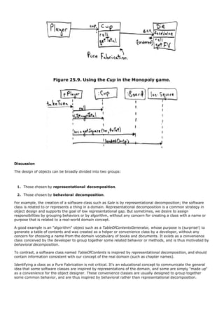
![Said another way, a Pure Fabrication is usually partitioned based on related functionality, so it is a kind of
function-centric or behavioral object.
Many existing object-oriented design patterns are examples of Pure Fabrications: Adapter, Strategy, Command,
and so on [GHJV95].
As a final comment worth reiterating: Sometimes a solution offered by Information Expert is not desirable. Even
though the object is a candidate for the responsibility by virtue of having much of the information related to the
responsibility, in other ways, its choice leads to a poor design, usually due to problems in cohesion or coupling.
Benefits
High Cohesion is supported because responsibilities are factored into a fine-grained class that only focuses
on a very specific set of related tasks.
Reuse potential may increase because of the presence of fine-grained Pure Fabrication classes whose
responsibilities have applicability in other applications.
Contraindications
Behavioral decomposition into Pure Fabrication objects is sometimes overused by those new to object design
and more familiar with decomposing or organizing software in terms of functions. To exaggerate, functions just
become objects. There is nothing inherently wrong with creating "function" or "algorithm" objects, but it needs
to be balanced with the ability to design with representational decomposition, such as the ability to apply
Information Expert so that a representational class such as Sale also has responsibilities. Information Expert
supports the goal of co-locating responsibilities with the objects that know the information needed for those
responsibilities, which tends to support lower coupling. If overused, Pure Fabrication could lead to too many
behavior objects that have responsibilities not co-located with the information required for their fulfillment,
which can adversely affect coupling. The usual symptom is that most of the data inside the objects is being
passed to other objects to reason with it.
Related Patterns and Principles
Low Coupling.
High Cohesion.
A Pure Fabrication usually takes on responsibilities from the domain class that would be assigned those
responsibilities based on the Expert pattern.
All GoF design patterns [GHJV95], such as Adapter, Command, Strategy, and so on, are Pure Fabrications.
Virtually all other design patterns are Pure Fabrications.](https://image.slidesharecdn.com/softwaredevleopment-100607174022-phpapp01/85/Software-Development-545-320.jpg)
![25.3. Indirection
Problem
Where to assign a responsibility, to avoid direct coupling between two (or more) things? How to de-couple
objects so that low coupling is supported and reuse potential remains higher?
Solution
Assign the responsibility to an intermediate object to mediate between other components or services so that
they are not directly coupled.
The intermediary creates an indirection between the other components.
Examples
TaxCalculatorAdapter
These objects act as intermediaries to the external tax calculators. Via polymorphism, they provide a consistent
interface to the inner objects and hide the variations in the external APIs. By adding a level of indirection and
adding polymorphism, the adapter objects protect the inner design against variations in the external interfaces
(see Figure 25.10).
Figure 25.10. Indirection via the adapter.
[View full size image]
Applying UML: Notice how the external TaxMaster remote service application is modeled in Figure 25.10: It's
labeled with the «actor» keyword to indicate it's an external software component to our NextGen system.
PersistentStorage
The Pure Fabrication example of decoupling the Sale from the relational database services through the
introduction of a PersistentStorage class is also an example of assigning responsibilities to support Indirection.
The PersistentStorage acts as a intermediary between the Sale and the database.
Discussion](https://image.slidesharecdn.com/softwaredevleopment-100607174022-phpapp01/85/Software-Development-546-320.jpg)
!["Most problems in computer science can be solved by another level of indirection" is an old adage with particular
relevance to object-oriented designs. [3]
[3] By David Wheeler. Note there is also the counter-adage: "Most problems in performance can be solved by removing another layer of indirection!"
Just as many existing design patterns are specializations of Pure Fabrication, many are also specializations of
Indirection. Adapter, Facade, and Observer are examples [GHJV95]. In addition, many Pure Fabrications are
generated because of Indirection. The motivation for Indirection is usually Low Coupling; an intermediary is
added to decouple other components or services.
Benefits
Lower coupling between components.
Related Patterns and Principles
Protected Variations
Low Coupling
Many GoF patterns, such as Adapter, Bridge, Facade, Observer, and Mediator [GHJV95].
Many Indirection intermediaries are Pure Fabrications.](https://image.slidesharecdn.com/softwaredevleopment-100607174022-phpapp01/85/Software-Development-547-320.jpg)
![25.4. Protected Variations
Problem
How to design objects, subsystems, and systems so that the variations or instability in these elements does not
have an undesirable impact on other elements?
Solution
Identify points of predicted variation or instability; assign responsibilities to create a stable interface around
them.
Note: The term "interface" is used in the broadest sense of an access view; it does not literally only mean
something like a Java interface.
Example
For example, the prior external tax calculator problem and its solution with Polymorphism illustrate Protected
Variations (Figure 25.1). The point of instability or variation is the different interfaces or APIs of external tax
calculators. The POS system needs to be able to integrate with many existing tax calculator systems, and also
with future third-party calculators not yet in existence.
By adding a level of indirection, an interface, and using polymorphism with various ITaxCalculatorAdapter
implementations, protection within the system from variations in external APIs is achieved. Internal objects
collaborate with a stable interface; the various adapter implementations hide the variations to the external
systems.
Discussion
This is a very important, fundamental principle of software design! Almost every software or architectural design
trick in bookdata encapsulation, polymorphism, data-driven designs, interfaces, virtual machines, configuration
files, operating systems, and much moreis a specialization of Protected Variations.
Protected Variations (PV) was first published as a named pattern by Cockburn in [VCK96], although this very
fundamental design principle has been around for decades under various terms, such as the term information
hiding [Parnas72].
Mechanisms Motivated by Protected Variations
PV is a root principle motivating most of the mechanisms and patterns in programming and design to provide
flexibility and protection from variationsvariations in data, behavior, hardware, software components, operating
systems, and more.
At one level, the maturation of a developer or architect can be seen in their growing knowledge of ever-wider
mechanisms to achieve PV, to pick the appropriate PV battles worth fighting, and their ability to choose a
suitable PV solution. In the early stages, one learns about data encapsulation, interfaces, and polymorphismall
core mechanisms to achieve PV. Later, one learns techniques such as rule-based languages, rule interpreters,
reflective and metadata designs, virtual machines, and so forthall of which can be applied to protect against
some variation.
For example:
Core Protected Variations Mechanisms](https://image.slidesharecdn.com/softwaredevleopment-100607174022-phpapp01/85/Software-Development-548-320.jpg)
![Data encapsulation, interfaces, polymorphism, indirection, and standards are motivated by PV. Note that
components such as virtual machines and operating systems are complex examples of indirection to achieve PV.
Data-Driven Designs
Data-driven designs cover a broad family of techniques including reading codes, values, class file paths, class
names, and so forth, from an external source in order to change the behavior of, or "parameterize" a system in
some way at run-time. Other variants include style sheets, metadata for object-relational mapping, property
files, reading in window layouts, and much more. The system is protected from the impact of data, metadata, or
declarative variations by externalizing the variant, reading it in, and reasoning with it.
Service Lookup
Service lookup includes techniques such as using naming services (for example, Java's JNDI) or traders to
obtain a service (for example, Java's Jini, or UDDI for Web services). Clients are protected from variations in the
location of services, using the stable interface of the lookup service. It is a special case of data-driven design.
Interpreter-Driven Designs
Interpreter-driven designs include rule interpreters that execute rules read from an external source, script or
language interpreters that read and run programs, virtual machines, neural network engines that execute nets,
constraint logic engines that read and reason with constraint sets, and so forth. This approach allows changing
or parameterizing the behavior of a system via external logic expressions. The system is protected from the
impact of logic variations by externalizing the logic, reading it in, and using an interpreter.
Reflective or Meta-Level Designs
An example of this approach is using the java.beans.Introspector to obtain a BeanInfo object, asking for the
getter Method object for bean property X, and calling Method.invoke. The system is protected from the impact
of logic or external code variations by reflective algorithms that use introspection and meta-language services.
It may be considered a special case of data-driven designs.
Uniform Access
Some languages, such as Ada, Eiffel, and C#, support a syntactic construct so that both a method and field
access are expressed the same way. For example, aCircle.radius may invoke a radius():float method or directly
refer to a public field, depending on the definition of the class. We can change from public fields to access
methods, without changing the client code.
Standard Languages
Official language standards such as SQL provide protection against a proliferation of varying languages.
The Liskov Substitution Principle (LSP)
LSP [Liskov88] formalizes the principle of protection against variations in different implementations of an
interface, or subclass extensions of a superclass.
To quote:
What is wanted here is something like the following substitution property: If for each object o1 of type S
there is an object o2 of type T such that for all programs P defined in terms of T, the behavior of P is](https://image.slidesharecdn.com/softwaredevleopment-100607174022-phpapp01/85/Software-Development-549-320.jpg)
![unchanged when o1 is substituted for o2 then S is a subtype of T [Liskov88].
Informally, software (methods, classes, …) that refers to a type T (some interface or abstract superclass) should
work properly or as expected with any substituted implementation or subclass of Tcall it S. For example:
public void addTaxes( ITaxCalculatorAdapter calculator, Sale sale )
{
List taxLineItems = calculator.getTaxes( sale );
// ...
}
For this method addTaxes, no matter what implementation of ITaxCalculatorAdapter is passed in as an actual
parameter, the method should continue to work "as expected." LSP is a simple idea, intuitive to most object
developers, that formalizes this intuition.
Structure-Hiding Designs
In the first edition of this book, an important, classic object design principle called Don't Talk to Strangers or
the Law of Demeter [Lieberherr88] was expressed as one of the nine GRASP patterns. Briefly, it means to
avoid creating designs that traverse long object structure paths and send messages (or talk) to distant, indirect
(stranger) objects. Such designs are fragile with respect to changes in the object structuresa common point of
instability. But in the second edition the more general PV replaced Don't Talk to Strangers, because the latter is
a special case of the former. That is, a mechanism to achieve protection from structure changes is to apply the
Don't Talk to Strangers rules.
Don't Talk to Strangers places constraints on what objects you should send messages to within a method. It
states that within a method, messages should only be sent to the following objects:
1. The this object (or self).
2. A parameter of the method.
3. An attribute of this.
4. An element of a collection which is an attribute of this.
5. An object created within the method.
The intent is to avoid coupling a client to knowledge of indirect objects and the object connections between
objects.
Direct objects are a client's "familiars," indirect objects are "strangers." A client should talk to familiars, and
avoid talking to strangers.
Here is an example that (mildly) violates Don't Talk to Strangers. The comments explain the violation.
class Register
{
private Sale sale;
public void slightlyFragileMethod()
{
// sale.getPayment() sends a message to a "familiar" (passes #3)
// but in sale.getPayment().getTenderedAmount()
// the getTenderedAmount() message is to a "stranger" Payment
Money amount = sale.getPayment().getTenderedAmount();](https://image.slidesharecdn.com/softwaredevleopment-100607174022-phpapp01/85/Software-Development-550-320.jpg)

![Money amount = sale.getTenderedAmountOfPayment();
// case 2
AccountHolder holder = sale.getAccountHolderOfPayment();
Contraindications
Caution: Speculative PV and Picking Your Battles
First, two points of change are worth defining:
variation pointVariations in the existing, current system or requirements, such as the multiple tax
calculator interfaces that must be supported.
evolution pointSpeculative points of variation that may arise in the future, but which are not present in
the existing requirements.[4]
[4]
In the UP, evolution points can be formally documented in Change Cases; each describes relevant aspects of an evolution point for the
benefit of a future architect.
PV is applied to both variation and evolution points.
A caution: Sometimes the cost of speculative "future-proofing" at evolution points outweighs the cost incurred
by a simple, more "brittle" design that is reworked as necessary in response to the true change pressures. That
is, the cost of engineering protection at evolution points can be higher than reworking a simple design.
For example, I recall a pager message-handling system where the architect added a scripting language and
interpreter to support flexibility and protected variation at an evolution point. However, during rework in an
incremental release, the complex (and inefficient) scripting was removedit simply wasn't needed. And when I
started OO programming (in the early 1980s) I suffered the disease of "generalize-itis" in which I tended to
spend many hours creating superclasses of the classes I really needed to write. I would make everything very
general and flexible (and protected against variations), for that future situation when it would really pay
offwhich never came. I was a poor judge of when it was worth the effort.
The point is not to advocate rework and brittle designs. If the need for flexibility and protection from change is
realistic, then applying PV is motivated. But if it is for speculative future-proofing or speculative "reuse" with
very uncertain probabilities, then restraint and critical thinking is called for.
Novice developers tend toward brittle designs, intermediate developers tend toward overly fancy and flexible,
generalized ones (in ways that never get used). Expert designers choose with insight; perhaps a simple and
brittle design whose cost of change is balanced against its likelihood.
Benefits
Extensions required for new variations are easy to add.
New implementations can be introduced without affecting clients.
Coupling is lowered.
The impact or cost of changes can be lowered.
Related Patterns and Principles
Most design principles and patterns are mechanisms for protected variation, including polymorphism,
interfaces, indirection, data encapsulation, most of the GoF design patterns, and so on.](https://image.slidesharecdn.com/softwaredevleopment-100607174022-phpapp01/85/Software-Development-552-320.jpg)
![In [Pree95] variation and evolution points are called "hot spots."
Also Known As; Similar To
PV is essentially the same as the information hiding and open-closed principles, which are older terms. As an
"official" pattern in the pattern community, it was named "Protected Variations" in 1996 by Cockburn in
[VCK96].
Information Hiding
David Parnas's famous paper On the Criteria To Be Used in Decomposing Systems Into Modules [Parnas72] is an
example of classics often cited but seldom read. In it, Parnas introduces the concept of information hiding.
Perhaps because the term sounds like the idea of data encapsulation, it has been misinterpreted as data
encapsulation, and some books erroneously define the concepts as synonyms. Rather, Parnas intended
information hiding to mean hide information about the design from other modules, at the points of difficulty or
likely change. To quote his discussion of information hiding as a guiding design principle:
We propose instead that one begins with a list of difficult design decisions or design decisions which are
likely to change. Each module is then designed to hide such a decision from the others.
That is, Parnas's information hiding is the same principle expressed in PV, and not simply data
encapsulationwhich is but one of many techniques to hide information about the design. However, the term has
been so widely reinterpreted as a synonym for data encapsulation that it is no longer possible to use it in its
original sense without misunderstanding.
Open-Closed Principle
The Open-Closed Principle (OCP), described by Bertrand Meyer in [Meyer88], is essentially equivalent to the
PV pattern and to information hiding. A definition of OCP is:
Modules should be both open (for extension; adaptable) and closed (the module is closed to modification in
ways that affect clients).
OCP and PV are essentially two expressions of the same principle, with different emphasis: protection at
variation and evolution points. In OCP, "module" includes all discrete software elements, including methods,
classes, subsystems, applications, and so forth.
In the context of OCP, the phrase "closed with respect to X" means that clients are not affected if X changes.
For example, "the class is closed with respect to instance field definitions" through the mechanism of data
encapsulation with private fields and public accessing methods. At the same time, they are open to modifying
the definitions of the private data, because outside clients are not directly coupled to the private data.
As another example, "the tax calculator adapters are closed with respect to their public interface" through
implementing the stable ITaxCalculatorAdapter interface. However, the adapters are open to extension by being
privately modified in response to changes in the APIs of the external tax calculators, in ways that do not break
their clients.](https://image.slidesharecdn.com/softwaredevleopment-100607174022-phpapp01/85/Software-Development-553-320.jpg)

![Introduction
This chapter explores OO design for use-case realizations for the NextGen case study, providing support for
external third-party services whose interfaces may vary, more complex product pricing rules, and pluggable
business rules. The emphasis is to show how to apply the Gang-of-Four (GoF) and the more basic GRASP
patterns. It illustrates that object design and the assignment of responsibilities can be explained and learned
based on the application of patternsa vocabulary of principles and idioms that can be combined to design
objects.
[View full size image]
Some of the 23 GoF design patterns are introduced here, but more are also covered in later chapters, including:
"More Object Design with GoF Patterns" on page 579
"Designing a Persistence Framework with Patterns" on page 625
The Gang-of-Four Design Patterns
GoF design patterns, and their seminal influence, were first introduced on p. 280. As a brief review, these were
first described in Design Patterns [GHJV95], a seminal and extremely popular work that presents 23 patterns
useful during object design.
Not all of the 23 patterns are widely used; perhaps 15 are common and most useful.
A thorough study of the Design Patterns book is recommended to grow as an object designer, although that
book assumes the reader is already an OO designer with significant experienceand has a background in C++
and Smalltalk. In contrast, this book offers an introduction.](https://image.slidesharecdn.com/softwaredevleopment-100607174022-phpapp01/85/Software-Development-555-320.jpg)
![26.1. Adapter (GoF)
The NextGen problem explored on p. 414 to motivate the Polymorphism pattern and its solution is more
specifically an example of the GoF Adapter pattern.
Name: Adapter
Problem: How to resolve incompatible interfaces, or provide a stable interface to similar
components with different interfaces?
Solution: (advice) Convert the original interface of a component into another interface, through an
intermediate adapter object.
To review: The NextGen POS system needs to support several kinds of external third-party services, including
tax calculators, credit authorization services, inventory systems, and accounting systems, among others. Each
has a different API, which can't be changed.
A solution is to add a level of indirection with objects that adapt the varying external interfaces to a consistent
interface used within the application. The solution is illustrated in Figure 26.1.
Figure 26.1. The Adapter pattern.
[View full size image]
As illustrated in Figure 26.2, a particular adapter instance will be instantiated for the chosen external service[1] ,
such as SAP for accounting, and will adapt the postSale request to the external interface, such as a SOAP XML
interface over HTTPS for an intranet Web service offered by SAP.
[1] In the J2EE Connector Architecture, these adapters to external services are more specifically called resource adapters.](https://image.slidesharecdn.com/softwaredevleopment-100607174022-phpapp01/85/Software-Development-556-320.jpg)
![Figure 26.2. Using an Adapter.
[View full size image]
Guideline: Include Pattern in Type Name
Notice that the type names include the pattern name "Adapter." This is a relatively common style
and has the advantage of easily communicating to others reading the code or diagrams what
design patterns are being used.
Related Patterns
A resource adapter that hides an external system may also be considered a Facade object (another GoF pattern
discussed in this chapter), as it wraps access to the subsystem or system with a single object (which is the
essence of Facade). However, the motivation to call it a resource adapter especially exists when the wrapping
object provides adaptation to varying external interfaces.](https://image.slidesharecdn.com/softwaredevleopment-100607174022-phpapp01/85/Software-Development-557-320.jpg)
![26.2. Some GRASP Principles as a Generalization of Other
Patterns
The previous use of the Adapter pattern can be viewed as a specialization of some GRASP building blocks:
Adapter supports Protected Variations with respect to changing external interfaces or third-party packages
through the use of an Indirection object that applies interfaces and Polymorphism.
What's the Problem? Pattern Overload!
The Pattern Almanac 2000 [Rising00] lists around 500 design patterns. And many hundreds more have been
published since then. The curious developer has no time to actually program given this reading list!
A Solution: See the Underlying Principles
Yes, it's important for an experienced designer to know in detail and by memory 50+ of the most important
design patterns, but few of us can learn or remember 1,000 patterns, or even start to organize that pattern
plethora into a useful taxonomy.
But there's good news: Most design patterns can be seen as specializations of a few basic GRASP principles.
Although it is indeed helpful to study detailed design patterns to accelerate learning, it is even more helpful to
see their underlying basic themes (Protected Variations, Polymorphism, Indirection, …) to help us to cut through
the myriad details and see the essential "alphabet" of design techniques being applied.
Example: Adapter and GRASP
Figure 26.1 illustrates my point that detailed design patterns can be analyzed in terms of the basic underlying
"alphabet" of GRASP principles. UML generalization relationships are used to suggest the conceptual
connections. At this point perhaps this idea seems academic or overly analytical. But it is truly the case that as
you spend some years applying and reflecting on myriad design patterns, you will increasingly come to feel that
it's the underlying themes that are important, and the fine details of Adapter or Strategy or whatever will
become secondary.
Figure 26.3. Relating Adapter to some core GRASP principles.
[View full size image]](https://image.slidesharecdn.com/softwaredevleopment-100607174022-phpapp01/85/Software-Development-558-320.jpg)


![26.4. Factory
This is also called Simple Factory or Concrete Factory. This pattern is not a GoF design pattern, but
extremely widespread. It is also a simplification of the GoF Abstract Factory pattern (p. 597), and often
described as a variation of Abstract Factory, although that's not strictly accurate. Nevertheless, because of its
prevalence and association with GoF, it is presented now.
The adapter raises a new problem in the design: In the prior Adapter pattern solution for external services with
varying interfaces, who creates the adapters? And how to determine which class of adapter to create, such as
TaxMaster-Adapter or GoodAsGoldTaxProAdapter?
If some domain object creates them, the responsibilities of the domain object are going beyond pure application
logic (such as sales total calculations) and into other concerns related to connectivity with external software
components.
This point underscores another fundamental design principle (usually considered an architectural design
principle): Design to maintain a separation of concerns. That is, modularize or separate distinct concerns into
different areas, so that each has a cohesive purpose. Fundamentally, it is an application of the GRASP High
Cohesion principle. For example, the domain layer of software objects emphasizes relatively pure application
logic responsibilities, whereas a different group of objects is responsible for the concern of connectivity to
external systems.
Therefore, choosing a domain object (such as a Register) to create the adapters does not support the goal of a
separation of concerns, and lowers its cohesion.
A common alternative in this case is to apply the Factory pattern, in which a Pure Fabrication "factory" object is
defined to create objects.
Factory objects have several advantages:
Separate the responsibility of complex creation into cohesive helper objects.
Hide potentially complex creation logic.
Allow introduction of performance-enhancing memory management strategies, such as object caching or
recycling.
Name: Factory
Problem: Who should be responsible for creating objects when there are special considerations,
such as complex creation logic, a desire to separate the creation responsibilities for better
cohesion, and so forth?
Solution: (advice) Create a Pure Fabrication object called a Factory that handles the creation.
A Factory solution is illustrated in Figure 26.5.
Figure 26.5. The Factory pattern.
[View full size image]](https://image.slidesharecdn.com/softwaredevleopment-100607174022-phpapp01/85/Software-Development-561-320.jpg)

![26.5. Singleton (GoF)
The ServicesFactory raises another new problem in the design: Who creates the factory itself, and how is it
accessed?
First, observe that only one instance of the factory is needed within the process. Second, quick reflection
suggests that the methods of this factory may need to be called from various places in the code, as different
places need access to the adapters for calling on the external services. Thus, there is a visibility problem: How
to get visibility to this single ServicesFactory instance?
One solution is pass the ServicesFactory instance around as a parameter to wherever a visibility need is
discovered for it, or to initialize the objects that need visibility to it, with a permanent reference. This is possible
but inconvenient; an alternative is the Singleton pattern.
Occasionally, it is desirable to support global visibility or a single access point to a single instance of a class
rather than some other form of visibility. This is true for the ServicesFactory instance.
Name: Singleton
Problem: Exactly one instance of a class is allowedit is a "singleton." Objects need a global and
single point of access.
Solution: (advice) Define a static method of the class that returns the singleton.
For example, Figure 26.6 shows an implementation of the Singleton pattern.
Figure 26.6. The Singleton pattern in the ServicesFactory class.
[View full size image]](https://image.slidesharecdn.com/softwaredevleopment-100607174022-phpapp01/85/Software-Development-563-320.jpg)
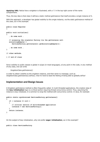
![{
// eager initialization
private static ServicesFactory instance =
new ServicesFactory();
public static ServicesFactory getInstance()
{
return instance;
}
// other methods...
}
The first approach of lazy initialization is usually preferred for at least these reasons:
Creation work (and perhaps holding on to "expensive" resources) is avoided, if the instance is never
actually accessed.
The getInstance lazy initialization sometimes contains complex and conditional creation logic.
Figure 26.7. Implicit getInstance Singleton pattern message indicated in the UML
because of the '1' mark.
[View full size image]
Another common Singleton implementation question is: Why not make all the service methods static methods of
the class itself, instead of using an instance object with instance-side methods? For example, what if we add a
static method called getAccountingAdapter to ServicesFactory. But, an instance and instance-side methods are
usually preferred for these reasons:
Instance-side methods permit subclassing and refinement of the singleton class into subclasses; static
methods are not polymorphic (virtual) and don't permit overriding in subclasses in most languages
(Smalltalk excluded).
Most object-oriented remote communication mechanisms (for example, Java's RMI) only support remote-
enabling of instance methods, not static methods. A singleton instance could be remote-enabled, although
that is admittedly rarely done.
A class is not always a singleton in all application contexts. In application X, it may be a singleton, but it
may be a "multi-ton" in application Y. It is also not uncommon to start off a design thinking the object will
be a singleton, and then discovering a need for multiple instances in the same process. Thus, the instance-
side solution offers flexibility.](https://image.slidesharecdn.com/softwaredevleopment-100607174022-phpapp01/85/Software-Development-565-320.jpg)

![26.6. Conclusion of the External Services with Varying
Interfaces Problem
A combination of Adapter, Factory, and Singleton patterns have been used to provide Protected Variations from
the varying interfaces of external tax calculators, accounting systems, and so forth. Figure 26.8 illustrates a
larger context of using these in the use-case realization.
Figure 26.8. Adapter, Factory, and Singleton patterns applied to the design.
[View full size image]
This design may not be ideal, and there is always room for improvement. But one of the goals strived for in this
case study is to illustrate that at least a design can be constructed from a set of principles or pattern "building
blocks," and that there is a methodical approach to doing and explaining a design. It is my sincere hope that it
is possible to see how the design in Figure 26.8 arose from reasoning based on Controller, Creator, Protected
Variations, Low Coupling, High Cohesion, Indirection, Polymorphism, Adapter, Factory, and Singleton.
Note how succinct a designer can be in conversation or documentation when there is a shared understanding of
patterns. I can say, "To handle the problem of varying interfaces for external services, let's use Adapters
generated from a Singleton Factory." Object designers really do have conversations that sound like this; using
patterns and pattern names supports raising the level of abstraction in design communication.](https://image.slidesharecdn.com/softwaredevleopment-100607174022-phpapp01/85/Software-Development-567-320.jpg)
![26.7. Strategy (GoF)
The next design problem to be resolved is to provide more complex pricing logic, such as a store-wide discount
for the day, senior citizen discounts, and so forth.
The pricing strategy (which may also be called a rule, policy, or algorithm) for a sale can vary. During one
period it may be 10% off all sales, later it may be $10 off if the sale total is greater than $200, and myriad
other variations. How do we design for these varying pricing algorithms?
Name: Strategy
Problem: How to design for varying, but related, algorithms or policies? How to design for the
ability to change these algorithms or policies?
Solution: (advice) Define each algorithm/policy/strategy in a separate class, with a common interface.
Since the behavior of pricing varies by the strategy (or algorithm), we create multiple SalePricingStrategy
classes, each with a polymorphic getTotal method (see Figure 26.9). Each getTotal method takes the Sale
object as a parameter, so that the pricing strategy object can find the pre-discount price from the Sale, and
then apply the discounting rule. The implementation of each getTotal method will be different:
PercentDiscountPricingStrategy will discount by a percentage, and so on.
Figure 26.9. Pricing Strategy classes.
[View full size image]
A strategy object is attached to a context objectthe object to which it applies the algorithm. In this example,
the context object is a Sale. When a getTotal message is sent to a Sale, it delegates some of the work to its
strategy object, as illustrated in Figure 26.10. It is not required that the message to the context object and the
strategy object have the same name, as in this example (for example, getTotal and getTotal), but it is common.
However, it is commonindeed, usually requiredthat the context object pass a reference to itself (this) on to the](https://image.slidesharecdn.com/softwaredevleopment-100607174022-phpapp01/85/Software-Development-568-320.jpg)
![strategy object, so that the strategy has parameter visibility to the context object, for further collaboration.
Figure 26.10. Strategy in collaboration.
[View full size image]
Observe that the context object (Sale) needs attribute visibility to its strategy. This is reflected in the DCD in
Figure 26.11.
Figure 26.11. Context object needs attribute visibility to its strategy.
[View full size image]
Creating a Strategy with a Factory
There are different pricing algorithms or strategies, and they change over time. Who should create the strategy?
A straightforward approach is to apply the Factory pattern again: A PricingStrategyFactory can be responsible
for creating all strategies (all the pluggable or changing algorithms or policies) needed by the application. As
with the ServicesFactory, it can read the name of the implementation class of the pricing strategy from a
system property (or some external data source), and then make an instance of it. With this partial data-driven
design (or reflective design) one can dynamically change at any timewhile the NextGen POS application is
runningthe pricing policy, by specifying a different class of Strategy to create.](https://image.slidesharecdn.com/softwaredevleopment-100607174022-phpapp01/85/Software-Development-569-320.jpg)
![Observe that a new factory was used for the strategies; that is, different than the ServicesFactory. This
supports the goal of High Cohesioneach factory is cohesively focused on creating a related family of objects.
UML Observe that in Figure 26.11 the reference via a directed association is to the interface
ISalePricingStrategy, not to a concrete class. This indicates that the reference attribute in the Sale will be
declared in terms of the interface, not a class, so that any implementation of the interface can be bound to the
attribute.
Note that because of the frequently changing pricing policy (it could be every hour), it is not desirable to cache
the created strategy instance in a field of the PricingStrategyFactory, but rather to re-create one each time, by
reading the external property for its class name, and then instantiating the strategy.
And as with most factories, the PricingStrategyFactory will be a singleton (one instance) and accessed via the
Singleton pattern (see Figure 26.12).
Figure 26.12. Factory for strategies.
When a Sale instance is created, it can ask the factory for its pricing strategy, as shown in Figure 26.13.
Figure 26.13. Creating a strategy.
[View full size image]
Reading and Initializing the Percentage Value
Finally, a design problem that has been ignored until now is the issue of how to find the different numbers for](https://image.slidesharecdn.com/softwaredevleopment-100607174022-phpapp01/85/Software-Development-570-320.jpg)


![explains the design idea in detail.
Figure 26.14. The Composite pattern.
[View full size image]
Observe that in this design, the composite classes such as CompositeBestForCustomerPricingStrategy inherit an
attribute pricingStrategies that contains a list of more ISalePricingStrategy objects. This is a signature feature of
a composite object: The outer composite object contains a list of inner objects, and both the outer and inner
objects implement the same interface. That is, the composite class itself implements the ISalePricingStrategy
interface.
Thus, we can attach either a composite CompositeBestForCustomerPricingStrategy object (which contains other
strategies inside of it) or an atomic PercentDiscountPricingStrategy object to the Sale object, and the Sale does
not know or care if its pricing strategy is an atomic or composite strategyit looks the same to the Sale object. It
is just another object that implements the ISalePricingStrategy interface and understands the getTotal message
(Figure 26.15).
Figure 26.15. Collaboration with a Composite.](https://image.slidesharecdn.com/softwaredevleopment-100607174022-phpapp01/85/Software-Development-573-320.jpg)
![[View full size image]
UML In Figure 26.15, please note a way to indicate objects that implement an interface, when we don't care to
specify the exact implementation class.
To clarify with some sample code in Java, the CompositePricingStrategy and one of its subclasses are defined as
follows:
// superclass so all subclasses can inherit a List of strategies
public abstract class CompositePricingStrategy
implements ISalePricingStrategy
{
protected List strategies = new ArrayList();
public add( ISalePricingStrategy s )
{
strategies.add( s );
}
public abstract Money getTotal( Sale sale );
} // end of class
// a Composite Strategy that returns the lowest total
// of its inner SalePricingStrategies
public class CompositeBestForCustomerPricingStrategy
extends CompositePricingStrategy
{
public Money getTotal( Sale sale )
{
Money lowestTotal = new Money( Integer.MAX_VALUE );
// iterate over all the inner strategies
for( Iterator i = strategies.iterator(); i.hasNext(); )
{](https://image.slidesharecdn.com/softwaredevleopment-100607174022-phpapp01/85/Software-Development-574-320.jpg)
![ISalePricingStrategy strategy =
(ISalePricingStrategy)i.next();
Money total = strategy.getTotal( sale );
lowestTotal = total.min( lowestTotal );
}
return lowestTotal;
}
} // end of class
Figure 26.16. Abstract superclasses, abstract methods, and inheritance in the
UML.
[View full size image]
Creating Multiple SalePricingStrategies
With the Composite pattern, we have made a group of multiple (and conflicting) pricing strategies look to the
Sale object like a single pricing strategy. The composite object that contains the group also implements the
ISalePricingStrategy interface. The more challenging (and interesting) part of this design problem is: When do
we create these strategies?
A desirable design will start by creating a Composite that contains the present moment's store discount policy
(which could be set to 0% discount if none is active), such as some PercentageDiscountPricingStrategy. Then, if
at a later step in the scenario, another pricing strategy is discovered to also apply (such as senior discount), it
will be easy to add it to the composite, using the inherited CompositePricingStrategy.add method.
There are three points in the scenario where pricing strategies may be added to the composite:
1. Current store-defined discount, added when the sale is created.
2. Customer type discount, added when the customer type is communicated to the POS.
3. Product type discount (if bought Darjeeling tea, 15% off the overall sale), added when the product is
entered to the sale.](https://image.slidesharecdn.com/softwaredevleopment-100607174022-phpapp01/85/Software-Development-575-320.jpg)
![3.
The design of the first case is shown in Figure 26.17. As in the original design discussed earlier, the strategy
class name to instantiate could be read as a system property, and a percentage value could be read from an
external data store.
Figure 26.17. Creating a composite strategy.
[View full size image]
For the second case of a customer type discount, first recall the use case extension which previously recognized
this requirement:
Use Case UC1: Process Sale
…
Extensions (or Alternative Flows):
5b. Customer says they are eligible for a discount (e.g., employee, preferred customer)
1. Cashier signals discount request.
Cashier enters Customer identification.
System presents discount total, based on discount rules.
This indicates a new system operation on the POS system, in addition to makeNewSale, enterItem, endSale, and
makePayment. We will call this fifth system operation enterCustomerForDiscount; it may optionally occur after
the endSale operation. It implies that some form of customer identification will have to come in through the
user interface, the customerID. Perhaps it can be captured from a card reader, or via the keyboard.
The design of the second case is shown in Figure 26.18 and Figure 26.19. Not surprisingly, the factory object is
responsible for the creation of the additional pricing strategy. It may make another
PercentageDiscountPricingStrategy that represents, for example, a senior discount. But as with the original
creation design, the choice of class will be read in as a system property, as will the specific percentage for the
customer type, to provide Protected Variations with respect to changing the class or values. Note that by virtue
of the Composite pattern, the Sale may have two or three conflicting pricing strategies attached to it, but it](https://image.slidesharecdn.com/softwaredevleopment-100607174022-phpapp01/85/Software-Development-576-320.jpg)
![continues to look like a single strategy to the Sale object.
Figure 26.18. Creating the pricing strategy for a customer discount, part 1.
[View full size image]
Figure 26.19. Creating the pricing strategy for a customer discount, part 2.
[View full size image]
UML Figure 26.18 and Figure 26.19 show an important UML 2 idea in interaction diagrams: Using the ref and sd
frame to relate diagrams.
Considering GRASP and Other Principles in the Design](https://image.slidesharecdn.com/softwaredevleopment-100607174022-phpapp01/85/Software-Development-577-320.jpg)


![26.9. Facade (GoF)
Another requirement chosen for this iteration is pluggable business rules. That is, at predictable points in the
scenarios, such as when makeNewSale or enterItem occurs in the Process Sale use case, or when a cashier
starts cashing in, different customers who wish to purchase the NextGen POS would like to customize its
behavior slightly.
To be more precise, assume that rules are desired that can invalidate an action. For example:
Suppose when a new sale is created, it is possible to identify that it will be paid by a gift certificate (this is
possible and common). Then, a store may have a rule to only allow one item to be purchased if a gift
certificate is used. Consequently, subsequent enterItem operations, after the first, should be invalidated.
If the sale is paid by a gift certificate, invalidate all payment types of change due back to the customer
except for another gift certificate. For example, if the cashier requested change in the form of cash, or as a
credit to the customer's store account, invalidate those requests.
Suppose when a new sale is created, it is possible to identify that it is for a charitable donation (from the
store to the charity). A store may also have a rule to only allow item entries less than $250 each, and also
to only add items to the sale if the currently logged in "cashier" is a manager.
In terms of requirements analysis, the specific scenario points across all use cases (enterItem,
chooseCashChange, ...) must be identified. For this exploration, only the enterItem point will be considered, but
the same solution applies equally to all points.
Suppose that the software architect wants a design that has low impact on the existing software components.
That is, she or he wants to design for a separation of concerns, and factor out this rule handling into a separate
concern. Furthermore, suppose that the architect is unsure of the best implementation for this pluggable rule
handling, and may want to experiment with different solutions for representing, loading, and evaluating the
rules. For example, rules can be implemented with the Strategy pattern, or with free open-source rule
interpreters that read and interpret a set of IF-THEN rules, or with commercial, purchased rule interpreters,
among other solutions.
To solve this design problem, the Facade pattern can be used.
Name: Facade
Problem: A common, unified interface to a disparate set of implementations or interfacessuch as
within a subsystemis required. There may be undesirable coupling to many things in the
subsystem, or the implementation of the subsystem may change. What to do?
Solution: (advice) Define a single point of contact to the subsystema facade object that wraps the
subsystem. This facade object presents a single unified interface and is responsible for
collaborating with the subsystem components.
A Facade is a "front-end" object that is the single point of entry for the services of a subsystem[2] ; the
implementation and other components of the subsystem are private and can't be seen by external components.
Facade provides Protected Variations from changes in the implementation of a subsystem.
[2] "Subsystem" is here used in an informal sense to indicate a separate grouping of related components, not exactly as defined in the UML.
For example, we will define a "rule engine" subsystem, whose specific implementation is not yet known.[3] It will
be responsible for evaluating a set of rules against an operation (by some hidden implementation), and then
indicating if any of the rules invalidated the operation.
[3] There are several free open source and commercial rule engines. For example, Jess, a free-for-academic-use rule engine available at](https://image.slidesharecdn.com/softwaredevleopment-100607174022-phpapp01/85/Software-Development-580-320.jpg)
![http://herzberg.ca.sandia.gov/jess/.
The facade object to this subsystem will be called POSRuleEngineFacade. See Figure 26.20. The designer
decides to place calls to this facade near the start of the methods that have been defined as the points for
pluggable rules, as in this example:
public class Sale
{
public void makeLineItem( ProductDescription desc, int quantity )
{
SalesLineItem sli = new SalesLineItem( desc, quantity );
// call to the Facade
if ( POSRuleEngineFacade.getInstance().isInvalid( sli, this ) )
return;
lineItems.add( sli );
}
// ...
} // end of class
Figure 26.20. UML package diagram with a Facade.
[View full size image]
Note the use of the Singleton pattern. Facades are often accessed via Singleton.
With this design, the complexity and implementation of how rules will be represented and evaluated are hidden
in the "rules engine" subsystem, accessed via the POSRuleEngineFacade facade. Observe that the subsystem
hidden by the facade object could contain dozens or hundreds of classes of objects, or even a non-object-
oriented solution, yet as a client to the subsystem, we see only its one public access point.](https://image.slidesharecdn.com/softwaredevleopment-100607174022-phpapp01/85/Software-Development-581-320.jpg)


![An example solution is described in detail in Figure 26.22.
Figure 26.22. The Observer pattern.
[View full size image]
The major ideas and steps in this example:
1. An interface is defined; in this case, PropertyListener with the operation onPropertyEvent.
2. Define the window to implement the interface.
SaleFrame1 will implement the method onPropertyEvent.
3. When the SaleFrame1 window is initialized, pass it the Sale instance from which it is displaying the total.
4. The SaleFrame1 window registers or subscribes to the Sale instance for notification of "property events,"
via the addPropertyListener message. That is, when a property (such as total) changes, the window wants
to be notified.
5. Note that the Sale does not know about SaleFrame1 objects; rather, it only knows about objects that
implement the PropertyListener interface. This lowers the coupling of the Sale to the windowthe coupling is
only to an interface, not to a GUI class.
6. The Sale instance is thus a publisher of "property events." When the total changes, it iterates across all
subscribing PropertyListeners, notifying each.
The SaleFrame1 object is the observer/subscriber/listener. In Figure 26.23, it subscribes to interest in property
events of the Sale, which is a publisher of property events. The Sale adds the object to its list of](https://image.slidesharecdn.com/softwaredevleopment-100607174022-phpapp01/85/Software-Development-584-320.jpg)
![PropertyListener subscribers. Note that the Sale does not know about the SaleFrame1 as a SaleFrame1 object,
but only as a PropertyListener object; this lowers the coupling from the model up to the view layer.
Figure 26.23. The observer SaleFrame1 subscribes to the publisher Sale.
As illustrated in Figure 26.24, when the Sale total changes, it iterates across all its registered subscribers, and
"publishes an event" by sending the onPropertyEvent message to each.
Figure 26.24. The Sale publishes a property event to all its subscribers.
Applying UML: Note the approach to handing polymorphic messages in an interaction diagram, in Figure
26.24. The onPropertyEvent message is polymorphic; the specific cases of polymorphic implementation will be
shown in other diagrams, as in Figure 26.25.
Figure 26.25. The subscriber SaleFrame1 receives notification of a published
event.
[View full size image]](https://image.slidesharecdn.com/softwaredevleopment-100607174022-phpapp01/85/Software-Development-585-320.jpg)
![SaleFrame1, which implements the PropertyListener interface, thus implements an onPropertyEvent method.
When the SaleFrame1 receives the message, it sends a message to its JTextField GUI widget object to refresh
with the new sale total. See Figure 26.25.
In this pattern, there is still some coupling from the model object (the Sale) to the view object (the
SaleFrame1). But it is a loose coupling to an interface independent of the presentation layerthe PropertyListener
interface. And the design does not require any subscriber objects to actually be registered with the publisher (no
objects have to be listening). That is, the list of registered PropertyListeners in the Sale can be empty. In
summary, coupling to a generic interface of objects that do not need to be present, and which can be
dynamically added (or removed), supports low coupling. Therefore, Protected Variations with respect to a
changing user interface has been achieved through the use of an interface and polymorphism.
Why Is It Called Observer, Publish-Subscribe, or Delegation Event Model?
Originally, this idiom was called publish-subscribe, and it is still widely known by that name. One object
"publishes events," such as the Sale publishing the "property event" when the total changes. No object may be
interested in this event, in which case, the Sale has no registered subscribers. But objects that are interested,
"subscribe" or register to interest in an event by asking the publishing to notify them. This was done with the
Sale.addPropertyListener message. When the event happens, the registered subscribers are notified by a
message.
It has been called Observer because the listener or subscriber is observing the event; that term was popularized
in Smalltalk in the early 1980s.
It has also been called the Delegation Event Model (in Java) because the publisher delegates handling of events
to "listeners" (subscribers; see Figure 26.26).
Figure 26.26. Who is the observer, listener, subscriber, and publisher?
[View full size image]](https://image.slidesharecdn.com/softwaredevleopment-100607174022-phpapp01/85/Software-Development-586-320.jpg)
![Observer Is Not Only for Connecting UIs and Model Objects
The previous example illustrated connecting a non-UI object to a UI object with Observer. However, other uses
are common.
The most prevalent use of this pattern is for GUI widget event handling, in both Java technologies (AWT and
Swing) and in Microsoft's .NET. Each widget is a publisher of GUI-related events, and other objects can
subscribe to interest in these. For example, a Swing JButton publishes an "action event" when it is pressed.
Another object will register with the button so that when it is pressed, the object is sent a message and can
take some action.
As another example, Figure 26.27 illustrates an AlarmClock, which is a publisher of alarm events and various
subscribers. This example is illustrative in that it emphasizes that many classes can implement the
AlarmListener interface, many objects can simultaneously be registered listeners, and all can react to the "alarm
event" in their own unique way.
Figure 26.27. Observer applied to alarm events, with different subscribers.
[View full size image]](https://image.slidesharecdn.com/softwaredevleopment-100607174022-phpapp01/85/Software-Development-587-320.jpg)


![Introduction
Inception and iteration-1 explored many basic OOA/D modeling basics. Iteration-2 narrowly emphasized object
design. This third iteration takes a broader view again, exploring a variety of analysis and design topics,
including:
more GoF design pattern, and their application to the design of frameworksin particular, a persistence
framework
architectural analysis; documenting architecture with the N+1 view model
process modeling with UML activity diagrams
generalization and specialization
the design of packages
[View full size image]](https://image.slidesharecdn.com/softwaredevleopment-100607174022-phpapp01/85/Software-Development-594-320.jpg)

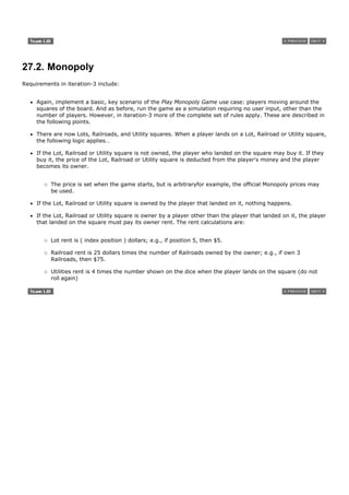

![Introduction
A UML activity diagram shows sequential and parallel activities in a process. They are useful for modeling
business processes, workflows, data flows, and complex algorithms.
[View full size image]](https://image.slidesharecdn.com/softwaredevleopment-100607174022-phpapp01/85/Software-Development-598-320.jpg)
![28.1. Example
Basic UML activity diagram notation is shown in Figure 28.1, illustrating an action, partition, fork, join, and
object node. In essence, this diagram shows a sequence of actions, some of which may be parallel. Most of the
notation is self-explanatory; two subtle points:
once an action is finished, there is an automatic outgoing transition
the diagram can show both control flow and data flow
Figure 28.1. Basic UML activity diagram notation.
[View full size image]](https://image.slidesharecdn.com/softwaredevleopment-100607174022-phpapp01/85/Software-Development-599-320.jpg)
![28.2. How to Apply Activity Diagrams?
A UML activity diagram offers rich notation to show a sequence of activities, including parallel activities. It
may be applied to any perspective or purpose, but is popular for visualizing business workflows and processes,
and use cases.
Business Process Modeling
One of my clients is in the express parcel shipping business. The process of shipping a parcel is very non-trivial;
there are many parties involved (customer, driver, …) and many steps. Although this process can be captured in
text (in use case text), in this case activity diagrams are a great example of pictures being worth a thousand
words. My client uses activity diagrams to understand their current complex business processes by visualizing
them. The partitions are useful to see the multiple parties and parallel actions involved in the shipping process,
and the object nodes illustrate what's moving around. After modeling their current process they visually explore
changes and optimizations. See Figure 28.1 for a simple example of applying UML activity diagrams to business
process modeling. To show the process model for my shipping client would fill an entire wall!
Data Flow Modeling
Starting in the 1970s, data flow diagrams (DFD) became a popular way to visualize the major steps and data
involved in software system processes. This is not the same as business process modeling; rather, DFDs were
usually used to show data flows in a computer system, although they could in theory be applied to business
process modeling. DFDs were useful to document the major data flows or to explore a new high-level design in
terms of data flow. See Figure 28.2 for an example DFD in the classic Gane-Sarson notation. Observe that the
process steps are numbered, to indicate order.
Figure 28.2. Classic DFD in Gane-Sarson notation.
[View full size image]
The information modeled in a DFD is useful, both for documentation and discovery, but the UML does not
include DFD notation. Fortunately, UML activity diagrams can satisfy the same goalsthey can be used for data
flow modeling, replacing traditional DFD notation. Figure 28.3 illustrates the same information as the DFD in
Figure 28.2, but using a UML activity diagram. Notice that in addition to object nodes being useful to show data
flow, the UML datastore node is applicable.](https://image.slidesharecdn.com/softwaredevleopment-100607174022-phpapp01/85/Software-Development-600-320.jpg)


![28.5. Example: NextGen Activity Diagram
The partial model in Figure 28.7 illustrates applying the UML to the Process Sale use case process. I've shown
this case-study example for completeness, but in reality would not bother to create this, as the use case text
and relative simplicity of the process make it of marginal value.
Figure 28.7. Modeling the Process Sale use case with an activity diagram.
[View full size image]](https://image.slidesharecdn.com/softwaredevleopment-100607174022-phpapp01/85/Software-Development-605-320.jpg)
![28.6. Process: Activity Diagrams in the UP
One of the UP disciplines is Business Modeling; its purpose is to understand and communicate "the structure
and the dynamics of the organization in which a system is to be deployed" [RUP]. A key artifact of the Business
Modeling discipline is the Business Object Model (a superset of the UP Domain Model), which essentially
visualizes how a business works, using UML class, sequence, and activity diagrams. Thus, activity diagrams are
especially applicable within the Business Modeling discipline of the UP.](https://image.slidesharecdn.com/softwaredevleopment-100607174022-phpapp01/85/Software-Development-606-320.jpg)


![Introduction
As with activity diagrams, UML state diagrams show a dynamic view. The UML includes notation to illustrate the
events and states of thingstransactions, use cases, people, and so forth.
The most important notational features are shown, but there are many rare elements not covered in this
introduction.
[View full size image]](https://image.slidesharecdn.com/softwaredevleopment-100607174022-phpapp01/85/Software-Development-609-320.jpg)
![29.1. Example
A UML state machine diagram, as shown in Figure 29.1, illustrates the interesting events and states of an
object, and the behavior of an object in reaction to an event. Transitions are shown as arrows, labeled with their
event. States are shown in rounded rectangles. It is common to include an initial pseudo-state, which
automatically transitions to another state when the instance is created.
Figure 29.1. State machine diagram for a telephone.
[View full size image]
A state machine diagram shows the lifecycle of an object: what events it experiences, its transitions, and the
states it is in between these events. It need not illustrate every possible event; if an event arises that is not
represented in the diagram, the event is ignored as far as the state machine diagram is concerned. Therefore,
we can create a state machine diagram that describes the lifecycle of an object at arbitrarily simple or complex
levels of detail, depending on our needs.](https://image.slidesharecdn.com/softwaredevleopment-100607174022-phpapp01/85/Software-Development-610-320.jpg)


![29.4. More UML State Machine Diagram Notation
Transition Actions and Guards
A transition can cause an action to fire. In a software implementation, this may represent the invocation of a
method of the class of the state machine diagram.
A transition may also have a conditional guardor boolean test. The transition only occurs if the test passes. See
Figure 29.2.
Figure 29.2. Transition action and guard notation.
Nested States
A state allows nesting to contain substates; a substate inherits the transitions of its superstate (the enclosing
state). See Figure 29.3. This was a key contribution of the Harel statechart approach that the UML is based on,
as it leads to succinct state machine diagrams. Substates may be graphically shown by nesting them in a
superstate box.
Figure 29.3. Nested states.
[View full size image]](https://image.slidesharecdn.com/softwaredevleopment-100607174022-phpapp01/85/Software-Development-614-320.jpg)


![Introduction
Use cases can be related to each other. For example, a subfunction use case such as Handle Credit Payment
may be part of several regular use cases, such as Process Sale and Process Rental. Organizing use cases into
relationships has no impact on the behavior or requirements of the system. Rather, it is simply an organization
mechanism to (ideally) improve communication and comprehension of the use cases, reduce duplication of text,
and improve management of the use case documents.
[View full size image]
Guideline: Avoid Agonizing Over Use Case Relationships
In some organizations working with use cases, way too much unproductive time is spent debating how to relate
use cases in a use case diagram, rather than the important use case work: writing text. It actually a reflects a
deeper problem in analysis-oriented work on software projects: Too much time wasted on low-value analysis
and modeling. It's part of the larger problem of waterfall thinking rather than iterative and evolutionary
thinking; if you think you have to "get it right" at the start, everything becomes bogged down in analysis
paralysis.
Consequently, although this chapter discusses relating use cases, the subject and its effort should be put in
perspective: It has some value, but the important work is writing use case text. Specifying the requirements is
done by writing text, not by organizing use casesan optional step to possibly improve their comprehension or
reduce duplication. If a team starts off use-case modeling by spending hours (or worse, days) discussing a use
case diagram and use case relationships ("Should that be an include or an extend relationship? Should we
specialize this use case?"), rather than quickly focusing on writing the key use case text, relative effort was
misplaced.
Plus, in the UP and other iterative methods, the organization of use cases into relationships can iteratively
evolve in small steps over the elaboration phase; it is not helpful to attempt a waterfall-like effort of fully
defining and refining a complete use case diagram and set of relationships in one step near the start of a
project.](https://image.slidesharecdn.com/softwaredevleopment-100607174022-phpapp01/85/Software-Development-621-320.jpg)
![30.1. The include Relationship
This is the most common and important relationship.
It is common to have some partial behavior that is common across several use cases. For example, the
description of paying by credit occurs in several use cases, including Process Sale, Process Rental, Contribute to
Lay-away Plan, and so forth. Rather than duplicate this text, it is desirable to separate it into its own
subfunction use case, and indicate its inclusion. This is simply refactoring and linking text to avoid duplication.[1]
[1] It is helpful if the links are implemented with navigable hyperlinks as well.
For example:
UC1: Process Sale
…
Main Success Scenario:
1.Customer arrives at a POS checkout with goods and/or services to purchase.
…
7.Customer pays and System handles payment.
…
Extensions:
7b. Paying by credit: Include Handle Credit Payment.
7c. Paying by check: Include Handle Check Payment.
…
UC7: Process Rental
…
Extensions:
6b. Paying by credit: Include Handle Credit Payment.
…
UC12: Handle Credit Payment](https://image.slidesharecdn.com/softwaredevleopment-100607174022-phpapp01/85/Software-Development-622-320.jpg)
![…
Level: Subfunction
Main Success Scenario:
1. Customer enters their credit account information.
2. System sends payment authorization request to an external Payment Authorization Service System, and
requests payment approval.
3. System receives payment approval and signals approval to Cashier.
4. …
Extensions:
2a. System detects failure to collaborate with external system:
1. System signals error to Cashier.
Cashier asks Customer for alternate payment.
…
This is the include relationship.
A slightly shorter (and thus perhaps preferred) notation to indicate an included use case is simply to underline it
or highlight it in some fashion. For example:
UC1: Process Sale
…
Extensions:
7b. Paying by credit: Handle Credit Payment.
7c. Paying by check: Handle Check Payment.
…
Notice that the Handle Credit Payment subfunction use case was originally in the Extensions section of the
Process Sale use case, but was factored out to avoid duplication. Also note that the same Main Success and
Extensions structures are used in the subfunction use case as in the regular elementary business process use
cases such as Process Sale.
A simple, practical guideline of when to use the include relationship is offered by Fowler [Fowler03]:
Use include when you are repeating yourself in two or more separate use cases and you want to avoid
repetition.
Another motivation is simply to decompose an overwhelmingly long use case into subunits to improve
comprehension.](https://image.slidesharecdn.com/softwaredevleopment-100607174022-phpapp01/85/Software-Development-623-320.jpg)
![Using include with Asynchronous Event Handling
Yet another use of the include relationship is to describe the handling of an asynchronous event, such as when a
user is able to, at any time, select or branch to a particular window, function, or Web page, or within a range of
steps.
In fact, the use case notation to support this asynchronous branching was already explored in the introduction
to use cases in Chapter 6, but at that time the addition of calling out to an included sub-use case was not
discussed.
The basic notation is to use the a*, b*, ... style labels in the Extensions section. Recall that these imply an
extension or event that can happen at any time. A minor variation is a range label, such as 3-9, to be used
when the asynchronous event can occur within a relatively large range of the use case steps, but not all.
UC1: Process FooBars
…
Main Success Scenario:
1. …
Extensions:
a*. At any time, Customer selects to edit personal information: Edit Personal Information.
b*. At any time, Customer selects printing help: Present Printing Help.
2-11. Customer cancels: Cancel Transaction Confirmation.
…
Summary
The include relationship can be used for most use case relationship problems. To summarize:
Factor out subfunction use cases and use the include relationship when:
They are duplicated in other use cases.
A use case is very complex and long, and separating it into subunits aids comprehension.
As will be explained, there are other relationships: extend and generalization. But Cockburn, an expert use-case
modeler, advises to prefer the include relationship over extend or generalization:
As a first rule of thumb, always use the include relationship between use cases. People who follow this rule
report they and their readers have less confusion with their writing than people who mix include with
extend and generalizes [Cockburn01].](https://image.slidesharecdn.com/softwaredevleopment-100607174022-phpapp01/85/Software-Development-624-320.jpg)

![30.2. Terminology: Concrete, Abstract, Base, and Addition Use
Cases
A concrete use case is initiated by an actor and performs the entire behavior desired by the actor [RUP].
These are the elementary business process use cases. For example, Process Sale is a concrete use case. By
contrast, an abstract use case is never instantiated by itself; it is a subfunction use case that is part of
another use case. Handle Credit Payment is abstract; it doesn't stand on its own, but is always part of another
story, such as Process Sale.
A use case that includes another use case, or that is extended or specialized by another use case is called a
base use case. Process Sale is a base use case with respect to the included Handle Credit Payment subfunction
use case. On the other hand, the use case that is an inclusion, extension, or specialization is called an addition
use case. Handle Credit Payment is the addition use case in the include relationship to Process Sale. Addition
use cases are usually abstract. Base use cases are usually concrete.](https://image.slidesharecdn.com/softwaredevleopment-100607174022-phpapp01/85/Software-Development-626-320.jpg)


![30.5. Use Case Diagrams
Figure 30.1 illustrates the UML notation for the include relationship, which is the only one being used in the case
study, following the advice of use-case experts to keep things simple and prefer the include relationship.
Figure 30.1. Use case include relationship in the Use-Case Model.
[View full size image]
The extend relationship notation is illustrated in Figure 30.2.
Figure 30.2. The extend relationship.](https://image.slidesharecdn.com/softwaredevleopment-100607174022-phpapp01/85/Software-Development-630-320.jpg)

![Introduction
The chapter quickly summarizes updates to SSDs and system operation contracts for this iteration of the
NextGen case study. No changes are necessary for the Monopoly problem.
[View full size image]](https://image.slidesharecdn.com/softwaredevleopment-100607174022-phpapp01/85/Software-Development-632-320.jpg)
![31.1. NextGen POS
New System Sequence Diagrams
In the current iteration, the new payment handling requirements involve new collaborations with external
systems. To review, SSDs use sequence diagram notation to illustrate inter-system collaborations, treating each
system as a blackbox. It is useful to illustrate the new system events in SSDs in order to clarify:
new system operations that the NextGen POS system will need to support
calls to other systems, and the responses to expect from these calls
Common Beginning of Process Sale Scenario
The SSD for the beginning portion of a basic scenario includes makeNewSale, enterItem, and endSale system
events; it is common regardless of the payment method (see Figure 31.1).
Figure 31.1. SSD common beginning.
[View full size image]
Credit Payment
This credit payment scenario SSD starts after the common beginning (see Figure 31.2).
Figure 31.2. Credit payment SSD.
[View full size image]](https://image.slidesharecdn.com/softwaredevleopment-100607174022-phpapp01/85/Software-Development-633-320.jpg)


![Introduction
Generalization and specialization are fundamental concepts in domain modeling that support an economy of
expression; further, conceptual class hierarchies are often the basis of inspiration for software class hierarchies
that exploit inheritance and reduce duplication of code. Association classes capture information about an
association itself. Time intervals capture the important concept that some business objects are valid for a
limited time. And packages are a way to organize large domain models into smaller units. Most of these
concepts are introduced in the context of the NextGen case study; a refined Monopoly domain model is shown
starting on p. 538.
[View full size image]](https://image.slidesharecdn.com/softwaredevleopment-100607174022-phpapp01/85/Software-Development-638-320.jpg)
![32.1. New Concepts for the NextGen Domain Model
As in iteration-1, the Domain Model may be incrementally developed by considering the concepts in the
requirements for this iteration. Techniques such as the Concept Category List and noun phrase identification will
help. An effective approach to developing a robust and rich domain model is to study the work of other authors
on this subject, such as [Fowler96].
Concepts Category List
Table 32.1 shows some noteworthy concepts being considered in this iteration.
Table 32.1. Category Concepts List
Category Examples
physical or tangible objects CreditCard, Check
Transactions CashPayment, CreditPayment, CheckPayment
other computer or electro-mechanical systems CreditAuthorizationService, CheckAuthorizationService
external to our system
abstract noun concepts
organizations CreditAuthorizationService, CheckAuthorizationService
records of finance, work, contracts, legal matters AccountsReceivable
Noun Phrase Identification from the Use Cases
To reiterate, noun phrase identification cannot be mechanically applied to identify relevant concepts to include in
the domain model. Judgement must be applied and suitable abstractions developed, since natural language is
ambiguous and relevant concepts are not always explicit or clear in existing text. However, it is a practical
technique in domain modeling since it is straightforward.
This iteration handles the scenarios of the Process Sale use case for credit and check payments. The following
shows some noun phrase identification from these extensions:
Use Case UC1: Process Sale](https://image.slidesharecdn.com/softwaredevleopment-100607174022-phpapp01/85/Software-Development-639-320.jpg)


![32.2. Generalization
The concepts CashPayment, CreditPayment, and CheckPayment are all very similar. In this situation, it is
possible (and useful[1]) to organize them (as in Figure 32.1) into a generalization-specialization class
hierarchy (or simply class hierarchy) in which the superclass Payment represents a more general concept,
and the subclasses more specialized ones.
[1] Later in the chapter, we will investigate reasons to define class hierarchies.
Figure 32.1. Generalization-specialization hierarchy.
[View full size image]
Note that the discussion of classes in this chapter refers to conceptual classes, not software classes.
Generalization is the activity of identifying commonality among concepts and defining superclass (general
concept) and subclass (specialized concept) relationships. It is a way to construct taxonomic classifications
among concepts which are then illustrated in class hierarchies.
Identifying a superclass and subclasses is of value in a domain model because their presence allows us to
understand concepts in more general, refined and abstract terms. It leads to economy of expression, improved
comprehension and a reduction in repeated information. And although we are focusing now on the UP Domain
Model and not the software Design Model, the later design and implementation of super- and subclass as
software classes that use inheritance yields better software.
Thus:
Guideline
Identify domain superclasses and subclasses relevant to the current iteration, and illustrate them
in the Domain Model.
UML To review the generalization notation introduced in a prior chapter, in the UML the generalization
relationship between elements is indicated with a large hollow triangle pointing to the more general element
from the more specialized one (see Figure 32.2). Either a separate target or shared target arrow style may be
used.
Figure 32.2. Class hierarchy with separate and shared arrow notations.](https://image.slidesharecdn.com/softwaredevleopment-100607174022-phpapp01/85/Software-Development-642-320.jpg)
![[View full size image]](https://image.slidesharecdn.com/softwaredevleopment-100607174022-phpapp01/85/Software-Development-643-320.jpg)
![32.3. Defining Conceptual Superclasses and Subclasses
Since it is valuable to identify conceptual super- and subclasses, it is useful to clearly and precisely understand
generalization, superclasses, and subclasses in terms of class definition and class sets.[2] This following sections
explore these.
[2] That is, a class's intension and extension. This discussion was inspired by [MO95].
Generalization and Conceptual Class Definition
What is the relationship of a conceptual superclass to a subclass?
Definition
A conceptual superclass definition is more general or encompassing than a subclass definition.
For example, consider the superclass Payment and its subclasses (CashPayment, and so on). Assume the
definition of Payment is that it represents the transaction of transferring money (not necessarily cash) for a
purchase from one party to another, and that all payments have an amount of money transferred. The model
corresponding to this is shown in Figure 32.3.
Figure 32.3. Payment class hierarchy.
A CreditPayment is a transfer of money via a credit institution which needs to be authorized. My definition of
Payment encompasses and is more general than my definition of CreditPayment.
Generalization and Class Sets
Conceptual subclasses and superclasses are related in terms of set membership.](https://image.slidesharecdn.com/softwaredevleopment-100607174022-phpapp01/85/Software-Development-644-320.jpg)

![Guideline: 100% Rule
100% of the conceptual superclass's definition should be applicable to the subclass. The subclass
must conform to 100% of the superclass's:
attributes
associations
Conceptual Subclass Set Conformance
A conceptual subclass should be a member of the set of the superclass. Thus, CreditPayment should be a
member of the set of Payments.
Informally, this expresses the notion that the conceptual subclass is a kind of superclass. CreditPayment is a
kind of Payment. More tersely, is-a-kind-of is called is-a.
This kind of conformance is the Is-a Rule:
Guideline: Is-a Rule
All the members of a subclass set must be members of their superclass set.
In natural language, this can usually be informally tested by forming the statement: Subclass is a
Superclass.
For instance, the statement CreditPayment is a Payment makes sense, and conveys the notion of set
membership conformance.
What Is a Correct Conceptual Subclass?
From the above discussion, apply the following tests[3] to define a correct subclass when constructing a domain
model:
[3] These rule names have been chosen for their mnemonic support rather than precision.
Guideline
A potential subclass should conform to the:
100% Rule (definition conformance)
Is-a Rule (set membership conformance)](https://image.slidesharecdn.com/softwaredevleopment-100607174022-phpapp01/85/Software-Development-646-320.jpg)

![32.4. When to Define a Conceptual Subclass?
Rules to ensure that a subclass is correct have been examined (the Is-a and 100% rules). However, when
should we even bother to define a subclass? First, a definition: A conceptual class partition is a division of a
conceptual class into disjoint subclasses (or types in Odell's terminology) [MO95]. The question may be
restated as: "When is it useful to show a conceptual class partition?"
For example, in the POS domain, Customer may be correctly partitioned (or subclassed) into MaleCustomer and
FemaleCustomer. But is it relevant or useful to show this in our model (see Figure 32.6)? This partition is not
useful for our domain; the next section explains why.
Figure 32.6. Legal conceptual class partition, but is it useful in our domain?
Motivations to Partition a Conceptual Class into Subclasses
The following are strong motivations to partition a class into subclasses:
Guideline
Create a conceptual subclass of a superclass when:
1. The subclass has additional attributes of interest.
2. The subclass has additional associations of interest.
3. The subclass concept is operated on, handled, reacted to, or manipulated differently than the
superclass or other subclasses, in ways that are of interest.
4. The subclass concept represents an animate thing (for example, animal, robot) that behaves
differently than the superclass or other subclasses, in ways that are of interest.
Based on the above criteria, it is not compelling to partition Customer into the subclasses MaleCustomer and
FemaleCustomer because they have no additional attributes or associations, are not operated on (treated)
differently, and do not behave differently in ways that are of interest[4].](https://image.slidesharecdn.com/softwaredevleopment-100607174022-phpapp01/85/Software-Development-648-320.jpg)
![[4] Men and women do exhibit different shopping habits. However, these are not relevant to our current use case requirementsthe criterion that
bounds our investigation.
Table 32.2 shows some examples of class partitions from the domain of payments and other areas, using these
criteria.
Table 32.2. Example subclass partitions.
Conceptual Subclass Motivation Examples
The subclass has additional attributes of interest. Payments not applicable.
Library Book, subclass of LoanableResource, has an
ISBN attribute.
The subclass has additional associations of interest. Payments CreditPayment, subclass of Payment, is
associated with a CreditCard.
Library Video, subclass of LoanableResource, is
associated with Director.
The subclass concept is operated upon, handled, reacted Payments CreditPayment, subclass of Payment, is
to, or manipulated differently than the superclass or handled differently than other kinds of payments in
other subclasses, in ways that are of interest. how it is authorized.
Library Software, subclass of LoanableResource,
requires a deposit before it may be loaned.
The subclass concept represents an animate thing (for Payments not applicable.
example, animal, robot) that behaves differently than
the superclass or other subclasses, in ways that are of Library not applicable.
interest.
Market Research MaleHuman, subclass of Human,
behaves differently than FemaleHuman with respect
to shopping habits.](https://image.slidesharecdn.com/softwaredevleopment-100607174022-phpapp01/85/Software-Development-649-320.jpg)

![32.6. NextGen POS Conceptual Class Hierarchies
Payment Classes
Based on the above criteria for partitioning the Payment class, it is useful to create a class hierarchy of various
kinds of payments. The justification for the superclass and subclasses is shown in Figure 32.7.
Figure 32.7. Justifying Payment subclasses.
[View full size image]
Authorization Service Classes
Credit and check authorization services are variations on a similar concept, and have common attributes of
interest. This leads to the class hierarchy in Figure 32.8.
Figure 32.8. Justifying the AuthorizationService hierarchy.
[View full size image]](https://image.slidesharecdn.com/softwaredevleopment-100607174022-phpapp01/85/Software-Development-651-320.jpg)
![Authorization Transaction Classes
Modeling the various kinds of authorization service transactions (requests and replies) presents an interesting
case. In general, transactions with external services are useful to show in a domain model because activities and
processes tend to revolve around them. They are important concepts.
Should the modeler illustrate every variation of an external service transaction? It depends. As mentioned,
domain models are not necessarily correct or wrong, but rather more or less useful. They are useful, because
each transaction class is related to different concepts, processes, and business rules.[5]
[5] In telecommunications domain models, it is similarly useful to identify each kind of exchange or switch message.
A second interesting question is the degree of generalization that is useful to show in the model. For argument's
sake, let us assume that every transaction has a date and time. These common attributes, plus the desire to
create an ultimate generalization for this family of related concepts, justifies the creation of
PaymentAuthorizationTransaction.
But is it useful to generalize a reply into a CreditPaymentAuthorizationReply and
CheckPaymentAuthorizationReply, as shown in Figure 32.9, or is it sufficient to show less generalization, as
depicted in Figure 32.10?
Figure 32.9. One possible class hierarchy for external service transactions.
[View full size image]](https://image.slidesharecdn.com/softwaredevleopment-100607174022-phpapp01/85/Software-Development-652-320.jpg)
![Figure 32.10. An alternate transaction class hierarchy.
[View full size image]
The class hierarchy shown in Figure 32.10 is sufficiently useful in terms of generalization, because the additional
generalizations do not add obvious value. The hierarchy of Figure 32.9 expresses a finer granularity of
generalization that does not significantly enhance our understanding of the concepts and business rules, but it
does make the model more complexand added complexity is undesirable unless it confers other benefits.](https://image.slidesharecdn.com/softwaredevleopment-100607174022-phpapp01/85/Software-Development-653-320.jpg)
![32.7. Abstract Conceptual Classes
It is useful to identify abstract classes in the domain model because they constrain what classes it is possible to
have concrete instances of, thus clarifying the rules of the problem domain.
Definition
If every member of a class C must also be a member of a subclass, then class C is called an
abstract conceptual class.
For example, assume that every Payment instance must more specifically be an instance of the subclass
CreditPayment, CashPayment, or CheckPayment. This is illustrated in the Venn diagram of Figure 32.11 (b).
Since every Payment member is also a member of a subclass, Payment is an abstract conceptual class by
definition.
Figure 32.11. Abstract conceptual classes.
[View full size image]
By contrast, if there can be Payment instances that are not members of a subclass, it is not an abstract class, as
illustrated in Figure 32.11 (a).
In the POS domain, every Payment is really a member of a subclass. Figure 32.11 (b) is the correct depiction of
payments; therefore, Payment is an abstract conceptual class.
Abstract Class Notation in the UML](https://image.slidesharecdn.com/softwaredevleopment-100607174022-phpapp01/85/Software-Development-654-320.jpg)
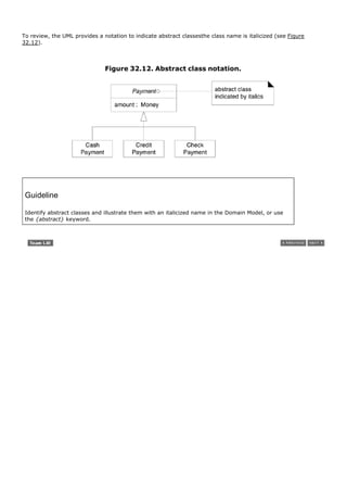


![The fact that both Store and AuthorizationService are related to ServiceContract is a clue that it is dependent on
the relationship between the two. The merchantID may be thought of as an attribute related to the association
between Store and AuthorizationService.
This leads to the notion of an association class, in which we can add features to the association itself.
ServiceContract may be modeled as an association class related to the association between Store and
AuthorizationService.
In the UML, this is illustrated with a dashed line from the association to the association class. Figure 32.16
visually communicates the idea that a ServiceContract and its attributes are related to the association between
a Store and AuthorizationService, and that the lifetime of the ServiceContract is dependent on the relationship.
Figure 32.16. An association class.
[View full size image]
Guidelines for adding association classes include the following:
Guideline
Clues that an association class might be useful in a domain model:
An attribute is related to an association.
Instances of the association class have a lifetime dependency on the association.
There is a many-to-many association between two concepts and information associated with
the association itself.
The presence of a many-to-many association is a common clue that a useful association class is lurking in the](https://image.slidesharecdn.com/softwaredevleopment-100607174022-phpapp01/85/Software-Development-659-320.jpg)

![32.11. Aggregation and Composition
These first few paragraphs repeat the introduction on p. 264. Aggregation is a vague kind of association in the
UML that loosely suggests whole-part relationships (as do many ordinary associations). It has no meaningful
distinct semantics in the UML versus a plain association, but the term is defined in the UML. Why? To quote
Rumbaugh (one of the original and key UML creators):
In spite of the few semantics attached to aggregation, everybody thinks it is necessary (for different
reasons). Think of it as a modeling placebo. [RJB04]
Guideline: Therefore, following the advice of UML creators, don't bother to use aggregation in the UML; rather,
use composition when appropriate.
Composition, also known as composite aggregation, is a strong kind of whole-part aggregation and is useful
to show in some models. A composition relationship implies that 1) an instance of the part (such as a Square)
belongs to only one composite instance (such as one Board) at a time, 2) the part must always belong to a
composite (no free-floating Fingers), and 3) the composite is responsible for the creation and deletion of its
partseither by itself creating/deleting the parts, or by collaborating with other objects. Related to this constraint
is that if the composite is destroyed, its parts must either be destroyed, or attached to another compositeno
free-floating Fingers allowed! For example, if a physical paper Monopoly game board is destroyed, we think of
the squares as being destroyed as well (a conceptual perspective). Likewise, if a software Board object is
destroyed, its software Square objects are destroyed, in a DCD software perspective.
How to Identify Composition
In some cases, the presence of composition is obvioususually in physical assemblies. But sometimes, it is not
clear.
Guideline
On composition: If in doubt, leave it out.
Here are some guidelines that suggest when to show aggregation:](https://image.slidesharecdn.com/softwaredevleopment-100607174022-phpapp01/85/Software-Development-661-320.jpg)
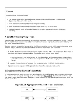

![32.12. Time Intervals and Product PricesFixing an Iteration 1
"Error"
In the first iteration, SalesLineItems were associated with ProductDescriptions, that recorded the price of an
item. This was a reasonable simplification for early iterations, but needs to be amended. It raises the
interestingand widely applicableissue of time intervals associated with information, contracts, and the like.
If a SalesLineItem always retrieved the current price recorded in a ProductDescriptions, then when the price was
changed in the object, old sales would refer to new prices, which is incorrect. What is needed is a distinction
between the historical price when the sale was made, and the current price.
Depending on the information requirements, there are at least two ways to model this. One is to simply copy
the product price into the SalesLineItem, and maintain the current price in the ProductDescriptions.
The other approach, more robust, is to associate a collection of ProductPrices with a ProductDescriptions, each
with an associated applicable time interval. Thus, the organization can record all past prices (to resolve the sale
price problem, and for trend analysis) and also record future planned prices (see Figure 32.19). See [CLD99] for
a broader discussion of time intervals, under the category of Moment-Interval archetypes.
Figure 32.19. ProductPrices and time intervals.
[View full size image]
It is common that a collection of time interval related information needs to be maintained, rather than a simple
value. Physical, medical, and scientific measurements, and many accounting and legal artifacts have this
requirement.](https://image.slidesharecdn.com/softwaredevleopment-100607174022-phpapp01/85/Software-Development-664-320.jpg)

![32.14. Roles as Concepts versus Roles in Associations
In a domain model, a real-world roleespecially a human rolemay be modeled in a number of ways, such as a
discrete concept, or expressed as a role in an association.[6] For example, the role of cashier and manager may
be expressed in at least the two ways illustrated in Figure 32.21.
[6] For simplicity, other excellent solutions such as those discussed in [Fowler96] are not covered.
Figure 32.21. Two ways to model human roles.
The first approach may be called "roles in associations"; the second, "roles as concepts." Both approaches have
advantages.
Roles in associations are appealing because they are a relatively accurate way to express the notion that the
same instance of a person takes on multiple (and dynamically changing) roles in various associations. I, a
person, simultaneously or in sequence, may take on the role of writer, object designer, parent, and so on.
On the other hand, roles as concepts provides ease and flexibility in adding unique attributes, associations, and
additional semantics. Furthermore, the implementation of roles as separate classes is easier because of
limitations of current popular object-oriented programming languagesit is not convenient to dynamically mutate
an instance of one class into another, or dynamically add behavior and attributes as the role of a person
changes.](https://image.slidesharecdn.com/softwaredevleopment-100607174022-phpapp01/85/Software-Development-666-320.jpg)


![32.17. Reflexive Associations
A concept may have an association to itself; this is known as a reflexive association[7] (see Figure 32.25).
[7] [MO95] constrains the definition of reflexive associations further.
Figure 32.25. Reflexive association.](https://image.slidesharecdn.com/softwaredevleopment-100607174022-phpapp01/85/Software-Development-669-320.jpg)
![32.18. Using Packages to Organize the Domain Model
A domain model can easily grow large enough that it is desirable to factor it into packages of strongly related
concepts, as an aid to comprehension and parallel analysis work in which different people do domain analysis
within different sub-domains. The following sections illustrate a package structure for the UP Domain Model.
To review, a UML package is shown as a tabbed folder (see Figure 32.26). Subordinate packages may be shown
within it. The package name is within the tab if the package depicts its elements; otherwise, it is centered within
the folder itself.
Figure 32.26. A UML package.
Ownership and References
An element is owned by the package within which it is defined, but may be referenced in other packages. In that
case, the element name is qualified by the package name using the pathname format
PackageName::ElementName (see Figure 32.27). A class shown in a foreign package may be modified with new
associations, but must otherwise remain unchanged.
Figure 32.27. A referenced class in a package.
[View full size image]
Package Dependencies](https://image.slidesharecdn.com/softwaredevleopment-100607174022-phpapp01/85/Software-Development-670-320.jpg)

![Core/Misc Package
A Core/Misc package (see Figure 32.30) is useful to own widely shared concepts or those without an obvious
home. In later references, the package name will be abbreviated to Core.
Figure 32.30. Core package.
There are no new concepts or associations particular to this iteration in this package.
Payments
As in iteration 1, new associations are primarily motivated by a need-to-know criterion. For example, there is a
need to remember the relationship between CreditPayment and CreditCard. In contrast, some associations are
added more for comprehension, such as DriversLicense Identifies Customer (see Figure 32.31).
Figure 32.31. Payments package.
[View full size image]](https://image.slidesharecdn.com/softwaredevleopment-100607174022-phpapp01/85/Software-Development-672-320.jpg)

![Sales
With the exception of composite aggregation and derived attributes, there are no new concepts or associations
particular to this iteration (see Figure 32.33).
Figure 32.33. Sales package.
[View full size image]
Authorization Transactions
Although providing meaningful names for associations is recommended, in some circumstances it may not be
compelling, especially if the purpose of the association is considered obvious to the audience. A case in point is
the associations between payments and their transactions. Their names have been left unspecified because we
can assume the audience reading the class diagram in Figure 32.34 will understand that the transactions are for
the payment; adding the names merely makes the diagram more busy.
Figure 32.34. Authorization transaction package.
[View full size image]](https://image.slidesharecdn.com/softwaredevleopment-100607174022-phpapp01/85/Software-Development-674-320.jpg)


![Introduction
Architectural analysis can be viewed as a specialization of requirements analysis, with a focus on requirements
that strongly influence the "architecture." For example, identifying the need for a highly-secure system.
The essence of architectural analysis is to identify factors that should influence the architecture, understand
their variability and priority, and resolve them. The difficult part is knowing what questions to ask, weighing the
trade-offs, and knowing the many ways to resolve an architecturally significant factor, ranging from benign
neglect, to fancy designs, to third-party products.
A good architect earns her salary by having the experience to know what questions to ask and choosing skillful
means to resolve the factors.
[View full size image]
Why is architectural analysis important? It's useful to:
reduce the risk of missing something centrally important in the design of the systems
avoid applying excessive effort to low priority issues
help align the product with business goals
This chapter is an introduction to basic steps and ideas in architectural analysis from a UP perspective; that is,
to the method, rather than to tips and tricks of master architects. Thus, it is not a cookbook of architectural
solutionsa very large and context-dependent subject that is beyond the scope of this introductory book.
Nevertheless, the NextGen POS case study comments in the chapter do provide concrete examples of
architectural solutions.](https://image.slidesharecdn.com/softwaredevleopment-100607174022-phpapp01/85/Software-Development-678-320.jpg)


![33.5. The Science: Identification and Analysis of Architectural
Factors
Architectural Factors
Any and all of the FURPS+ requirements may have a significant influence on the architecture of a system,
ranging from reliability, to schedule, to skills, and to cost constraints. For example, a case of tight schedule with
limited skills and sufficient money probably favors buying or outsourcing to specialists, rather than building all
components in-house.
FURPS+ p. 56
However, the factors with the strongest architectural influence tend to be within the high-level FURPS+
categories of functionality, reliability, performance, supportability, implementation, and interface. Interestingly,
it is usually the non-functional quality attributes (such as reliability or performance) that give a particular
architecture its unique flavor, rather than its functional requirements. For example, the design in the NextGen
system to support different third-party components with unique interfaces, and the design to support easily
plugging in different sets of business rules.
In the UP, these factors with architectural implications are called architecturally significant requirements.
"Factors" is used here for brevity.
Many technical and organizational factors can be characterized as constraints that restrict the solution in some
way (such as, must run on Linux, or, the budget for purchasing third-party components is X).
Quality Scenarios
When defining quality requirements during architectural factor analysis, quality scenarios[1] are
recommended, as they define measurable (or at least observable) responses, and thus can be verified. It is not
much use to vaguely state "the system will be easy to modify" without some measure of what that means.[2]
[1]
A term used in various architectural methods promoted by the Software Engineering Institute (SEI); for example, in the Architecture Based
Design method.
[2]
Tom Gilb, the creator of perhaps the first iterative and evolutionary method, Evo, is also a long-time proponent of the need to quantify and
measure non-functional goals. His PLanguage structured requirements language emphasizes quantification.
Quantifying some things, such as performance goals and mean time between failure, are well known practices,
but quality scenarios extend this idea and encourage recording all (or at least, most) factors as measurable
statements.
Quality scenarios are short statements of the form <stimulus> <measurable response>; for example:
When the completed sale is sent to the remote tax calculator to add the taxes, the result is returned within
2 seconds "most" of the time, measured in a production environment under "average" load conditions.
When a bug report arrives from a NextGen beta test volunteer, reply with a phone call within 1 working](https://image.slidesharecdn.com/softwaredevleopment-100607174022-phpapp01/85/Software-Development-684-320.jpg)
![day.
Note that "most" and "average" will need further investigation and definition by the NextGen architect; a quality
scenario is not really valid until it is testable, which implies fully specified. Also, observe the qualification in the
first quality scenario in terms of the environment to which it applies. It does little good to specify a quality
scenario, verify that it passes in a lightly loaded development environment, but fail to evaluate it in a realistic
production environment.
Pick Your Battles
A caution: Writing these quality scenarios can be a mirage of usefulness. It's easy to write these detailed
specifications, but not to realize them. Will anyone ever really test them? How and by whom? A strong dose of
realism is required when writing these; there's no point in listing many sophisticated goals if no one will ever
really follow through on testing them.
pick your battles p. 432
There is a relationship here to the "pick your battles" discussion that was presented in an earlier chapter on the
Protected Variations pattern. What are the really critical make-or-break quality scenarios? For example, in an
airline reservation system, consistently fast transaction completion under very high load conditions is truly
critical to the success of the systemit must definitely be tested. In the NextGen system, the application really
must be fault-tolerant and fail over to local replicated services when the remote ones failit must definitely be
properly tested and validated. Therefore, focus on writing quality scenarios for the important battles, and follow
through with a plan for their evaluation.
Describing Factors
One important goal of architectural analysis is to understand the influence of the factors, their priorities, and
their variability (immediate need for flexibility and future evolution). Therefore, most architectural methods (for
example, see [HNS00]) advocate creating a table or tree with variations of the following information (the format
varies depending on the method). The following style shown in Table 33.1 is called a factor table, which in the
UP is part of the Supplementary Specification.
Table 33.1. Sample factor table. Legend: H-high. M-medium. SME-subject matter
expert.](https://image.slidesharecdn.com/softwaredevleopment-100607174022-phpapp01/85/Software-Development-685-320.jpg)


![33.7. The Art: Resolution of Architectural Factors
One could say the science of architecture is the collection and organization of information about the architectural
factors, as in the factor table. The art of architecture is making skillful choices to resolve these factors, in light
of trade-offs, interdependencies, and priorities.
Adept architects have knowledge in a variety of areas (for example, architectural styles and patterns,
technologies, products, pitfalls, and trends) and apply this to their decisions.
Recording Architectural Alternatives, Decisions, and Motivation
Ignoring for now principles of architectural decision-making, virtually all architectural methods recommend
keeping a record of alternative solutions, decisions, influential factors, and motivations for the noteworthy issues
and decisions.
Such records have been called technical memos [Cunningham96], issue cards [HNS00], and architectural
approach documents (SEI architectural proposals), with varying degrees of formality and sophistication. In
some methods, these memos are the basis for yet another step of review and refinement.
In the UP, the memos should be recorded in the SAD.
An important aspect of the technical memo is the motivation or rationale. When a future developer or architect
needs to modify the system,[3] it is immensely helpful to understand the motivations behind the design, such as
why a particular approach to recovery from remote service failure in the NextGen POS was chosen and others
rejected, in order to make informed decisions about changing the system.
[3] Or when four weeks have passed and the original architect has forgotten their own rationale!
Explaining the rationale of rejecting the alternatives is important, as during future product evolution, an
architect may reconsider these alternatives, or at least want to know what alternatives were considered, and
why one was chosen.
A sample technical memo follows that records an architectural decision for the NextGen POS. The exact format
is, of course, not important. Keep it simple and just record information that will help the future reader make an
informed decision when changing the system.](https://image.slidesharecdn.com/softwaredevleopment-100607174022-phpapp01/85/Software-Development-690-320.jpg)


![33.10. Recommended Resources
There is a growing body of architecture-related patterns, and general software architecture advice. Suggestions:
Beyond Software Architecture [Hohman03]. This useful guide, from someone experienced as both architect
and product manager, brings a business-oriented emphasis to architecture. Hohman shares his experience
with important issues seldom covered, such as the impact of the business model, licensing, and upgrades
on the software architecture.
Patterns of Enterprise Application Architecture [Fowler02].
Software Architecture in Practice [BCK98].
Pattern-Oriented Software Architecture, both volumes.
Pattern Languages of Program Design, all volumes. Each volume has a section on architecture-related
patterns.](https://image.slidesharecdn.com/softwaredevleopment-100607174022-phpapp01/85/Software-Development-699-320.jpg)

![Introduction
Logical architecture and the Layers pattern was introduced starting on p. 197. This chapter dives a bit
deeperlooking at some intermediate topics related to layered architectures.
[View full size image]](https://image.slidesharecdn.com/softwaredevleopment-100607174022-phpapp01/85/Software-Development-701-320.jpg)
![34.1. Example: NextGen Logical Architecture
example of common layers p. 202
Figure 34.1 illustrates a partial logical layered architecture for this iteration of NextGen application.
Figure 34.1. Partial logical view of layers in the NextGen application.
[View full size image]
Note the absence of an Application layer for this iteration of the design; as discussed later, it is not always
necessary.
Since this is iterative development, it is normal to create a design of layers that starts simple, and evolves over
the iterations of the elaboration phase. One goal of this phase is to have the core architecture established
(designed and implemented) by the end of the iterations in elaboration, but this does not mean doing a large
up-front speculative architectural design before starting to program. Rather, a tentative logical architecture is
designed in the early iterations, and it evolves incrementally through the elaboration phase.](https://image.slidesharecdn.com/softwaredevleopment-100607174022-phpapp01/85/Software-Development-702-320.jpg)
![Observe that just a few sample types are present in this package diagram; this is not only motivated by limited
page space in formatting this book, but is a signature quality of an architectural view diagramit only shows a
few noteworthy elements in order to concisely convey the big ideas of the architecturally significant aspects. The
idea in a UP architectural view document is to say to the reader, "I've chosen this small set of instructive
elements to convey the big ideas."
Comments on Figure 34.1:
There are other types in these packages; only a few are shown to indicate noteworthy aspects.
The Foundation layer was not shown in this view; the architect (me) decided it did not add interesting
information, even though the development team will certainly be adding some Foundation classes, such as
more advanced String manipulation utilities.
For now, a separate Application layer is not used. The responsibilities of control or session objects in the
Application layer are handled by the Register object. The architect will add an Application layer in a later
iteration as the behavior grows in complexity, and alternative client interfaces are introduced (such as a
Web browser and wireless networked handheld PDA).
Inter-Layer and Inter-Package Coupling
To help someone understand the NextGen logical architecture, it's also informative to include a diagram in the
logical view that illustrates noteworthy coupling between the layers and packages. A partial example is
illustrated in Figure 34.2.
Figure 34.2. Partial coupling between packages.
[View full size image]](https://image.slidesharecdn.com/softwaredevleopment-100607174022-phpapp01/85/Software-Development-703-320.jpg)

![In fact, Figure 34.3 illustrates probably the most common style of logical architecture diagram in the UMLa
package diagram that shows between perhaps 5 to 20 major packages, and their dependencies.
Inter-Layer and Inter-Package Interaction Scenarios
Package diagrams show static information. To help someone understand the dynamics in the NextGen logical
architecture, it's also useful to include a diagram of how objects across the layers connect and communicate.
Thus, an interaction diagram is helpful. In the spirit of an "architectural view" which hides uninteresting details,
and emphasizes what the architect wants to convey, an interaction diagram in the logical view of the
architecture focuses on the collaborations as they cross layer and package boundaries. A set of interaction
diagrams that illustrate architecturally significant scenarios (in the sense that they illustrate many aspects
of the large-scale or big ideas in the design) is thus useful.
For example, Figure 34.4 illustrates part of a Process Sale scenario that emphasizes the connection points
across the layers and packages.
Figure 34.4. An architecturally significant interaction diagram that emphasizes
cross-boundary connections.
[View full size image]](https://image.slidesharecdn.com/softwaredevleopment-100607174022-phpapp01/85/Software-Development-705-320.jpg)


![System Operations and Layers
The SSDs illustrate the system operations, hiding UI objects from the diagram. The system operations being
invoked on the system in Figure 34.9 are requests being generated by an actor via the UI layer, onto the
Application or Domain layer.
Figure 34.9. System operations in the SSDs and in terms of layers.
[View full size image]
Upward Collaboration with Observer
The Facade pattern is commonly used for "downward" collaboration from a higher to a lower layer, or for access
to services in another subsystem of the same layer. When the lower Application or Domain layer needs to](https://image.slidesharecdn.com/softwaredevleopment-100607174022-phpapp01/85/Software-Development-710-320.jpg)
![communicate upward with the UI layer, it is usually via the Observer pattern. That is, UI objects in the higher
UI layer implement an interface such as PropertyListener or AlarmListener, and are subscribers or listeners to
events (such as property or alarm events) coming from objects in the lower layers. The lower layer objects are
directly sending messages to the upper layer UI objects, but the coupling is only to the objects viewed as things
that implement an interface, such as PropertyListener, not viewed as specific GUI windows.
This was examined when the Observer pattern was introduced. Figure 34.10 summarizes the idea in relation to
layers.
Figure 34.10. Observer for "upward" communication to the UI layer.
[View full size image]
Relaxed Layered Coupling
The layers in most layered architectures are not coupled in the same limited sense as a network protocol based
on the OSI 7-Layer Model. In the protocol model, there is strict restriction that elements of layer N only access
the services of the immediate lower layer N-1.
This is rarely followed in information system architectures. Rather, the standard is a "relaxed layered" or
"transparent layered" architecture [BMRSS96], in which elements of a layer collaborate with or are coupled to
several other layers.
Comments on typical coupling between layers:
All higher layers have dependencies on the Technical Services and Foundations layer.
For example, in Java all layers depend on java.util package elements.
It is primarily the Domain layer that has dependency on the Business Infrastructure layer.
The UI layer makes calls on the Application layer, which makes service calls on the Domain layer; the UI
layer does not call on the Domain, unless there is no Application layer.
If it is a single-process "desktop" application, software objects in the Domain layer are directly visible to,](https://image.slidesharecdn.com/softwaredevleopment-100607174022-phpapp01/85/Software-Development-711-320.jpg)


!["low," or "specific" versus "general." which are fuzzy set terms. This is normal, and it is seldom necessary to
decide upon a definitive categorizationthe development team may consider an element roughly part of the
Technical Services and/or Foundations layer considered as a group, broadly called the Infrastructure layer.[1]
[1] Note that there are not well-established naming conventions for layers, and name overloading and contradiction in the architecture literature is
common.
For example:
Suppose this is a Java technologies project, and the open source logging framework Log4J (part of the
Jakarta project) has been chosen. Is logging part of the Technical Service or Foundation layer? Log4J is a
low-level, small, general framework. It is moderately a member of both the Technical Services and the
Foundations fuzzy sets.
Suppose this is a Web application, and the Jakarta Struts framework for web applications has been chosen.
Struts is a relatively high-level, large, specific technical framework. It is arguably strongly a member of the
Technical Services set, and weakly a member of the Foundation set.
But, one person's High-level Technical Service is another's Foundation…
Finally, it is not the case that the libraries provided by a software platform only represent low-level Foundation
services. For example, in both .NET and J2SE+J2EE, services include relatively high-level functions such as
naming and directory services.
Contraindications and Liabilities for Layers
In some contexts, adding layers introduces performance problems. For example, in a high-performance
graphics-intensive game, adding layers of abstraction and indirection on top of direct access to graphics
card components may introduce performance problems.
The Layers pattern is one of several core architectural patterns; it is not applicable to every problem. For
example, an alternate is Pipes and Filters [BMRSS96]. This is useful when the main theme of the
application involves processing something through a series transformations, such as image
transformations, and the ordering of the transformations is changeable. Yet even in the case when the
highest level architectural pattern is Pipes and Filters, individual pipes or filters can be design, with Layers.
Known Uses
A vast number of modern object-oriented systems (from desktop applications to distributed J2EE Web systems)
are developed with Layers; it might be harder to find one that is not, than is. Going farther back in history:
Virtual Machines and Operating Systems
Starting in the 1960s, operating system architects advocated the design of operating systems in terms of clearly
defined layers, where the "lower" layers encapsulated access to the physical resources and provided process and
I/O services, and higher layers called on these services. These included Multics [CV65] and the THE system
[Dijkstra68].
Earlier stillin the 1950sresearchers suggested the idea of a virtual machine (VM) with a bytecode universal
machine language (for example, UNCOL [Conway1958]), so that applications could be written at higher layers in
the architecture (and executed without recompilation across different platforms), on top of the virtual machine
layer, which in turn would sit on top of the operating system and machine resources. A VM layered architecture
was applied by Alan Kay in his landmark Flex object-oriented personal computer system [Kay68] and later
(1972) by Kay and Dan Ingalls in the influential Smalltalk virtual machine [GK76]the progenitor of more recent
VMs such as the Java Virtual Machine.](https://image.slidesharecdn.com/softwaredevleopment-100607174022-phpapp01/85/Software-Development-714-320.jpg)
![Information Systems: The Classic Three-Tier Architecture
An early influential description of a layered architecture for information systems that included a user interface
and persistent storage of data was known as a three-tier architecture (Figure 34.11), described in the 1970s
in [TK78]. The phrase did not achieve popularity until the mid 1990s, in part due to its promotion in
[Gartner95] as a solution to problems associated with the widespread use of two-tier architectures.
Figure 34.11. Classic view of a three-tier architecture.
The original term is now less common, but its motivation is still relevant.
A classic description of the vertical tiers in a three-tier architecture is:
1. Interface windows, reports, and so on.
2. Application Logic tasks and rules that govern the process.
3. Storage persistent storage mechanism.
The singular quality of a three-tier architecture is the separation of the application logic into a distinct logical
middle tier of software. The interface tier is relatively free of application processing; windows or Web pages
forward task requests to the middle tier. The middle tier communicates with the back-end storage layer.
There was some misunderstanding that the original description implied or required a physical deployment on
three computers, but the intended description was purely logical; the allocation of the tiers to compute nodes
could vary from one to three. See Figure 34.12.
Figure 34.12. A three-tier logical division deployed in two physical architectures.
[View full size image]](https://image.slidesharecdn.com/softwaredevleopment-100607174022-phpapp01/85/Software-Development-715-320.jpg)
![The three-tier architecture was contrasted by the Gartner Group with a two-tier design, in which, for example,
application logic is placed within window definitions, which read and write directly to a database; there is no
middle tier that separates out the application logic. Two-tier client-server architectures became especially
popular with the rise of tools such as Visual Basic and PowerBuilder.
Two-tier designs have (in some cases) the advantage of initial quick development, but can suffer the complaints
covered in the Problems section. Nevertheless, there are applications that are primarily simple CRUD (create,
retrieve, update, delete) data intensive systems, for which this is a suitable choice.
Related Patterns
Indirection layers can add a level of indirection to lower-level services.
Protected Variation layers can protect against the impact of varying implementations.
Low Coupling and High Cohesion layers strongly support these goals.
Its application specifically to object-oriented information systems is described in [Fowler96].
Also Known As
The Layers pattern is also known as Layered Architecture [Shaw96, Gemstone00].](https://image.slidesharecdn.com/softwaredevleopment-100607174022-phpapp01/85/Software-Development-716-320.jpg)

![34.5. Recommended Resources
There's a wealth of literature on layered architectures, both in print and on the Web. A series of patterns in
Pattern Languages of Program Design, volume 1, [CS95] first address the topic in pattern form, although
layered architectures have been used and written about since at least the 1960s; volume 2 continues with
further layers-related patterns. Pattern-Oriented Software Architecture volume 1 [BMRSS96] provides a good
treatment of the Layers pattern.](https://image.slidesharecdn.com/softwaredevleopment-100607174022-phpapp01/85/Software-Development-718-320.jpg)

![Introduction
This chapter explores more OO designs, applying GoF and GRASP patterns, to the current iteration of both case
studies. For NextGen POS, we tackle requirements such as failover to local services, POS device handling, and
payment authorization, while demonstrating applying GoF patterns. For the Monopoly problem, we tackle
landing on property squares and buying or paying rent. Monopoly (starting on p. 607) demonstrates applying
basic GRASP principles.
[View full size image]](https://image.slidesharecdn.com/softwaredevleopment-100607174022-phpapp01/85/Software-Development-720-320.jpg)


![1. The ServicesFactory will always return an adapter to a local product information service.
2. The local products "adapter" is not really an adapter to another component. It will itself implement the
responsibilities of the local service.
3. The local service is initialized to a reference to a second adapter to the true remote product service.
4. If the local service finds the data in its cache, it returns it; otherwise, it forwards the request to the
adapter for the external service.
Note that there are two levels of client-side cache:
1. The in-memory ProductCatalog object will maintain an in-memory collection (such as a Java HashMap) of
some (for example, 1,000) ProductDescription objects that have been retrieved from the product
information service. The size of this collection can be adjusted depending on local memory availability.
2. The local products service will maintain a larger persistent (hard disk based) cache that maintains some
quantity of product information (such as 1 or 100MB of file space). Again, it can be adjusted depending on
the local configuration. This persistent cache is important for fault tolerance, so that even if the POS
application crashes and the in-memory cache of the ProductCatalog object is lost, the persistent cache
remains.
This design does not break existing codethe new local service object is inserted without affecting the design of
the ProductCatalog object (which collaborates with the product service).
So far, no new patterns have been introduced; Adapter and Factory are used.
Figure 35.1 illustrates the types in the design, and Figure 35.2 illustrates the initialization..
Figure 35.1. Adapters for product information.
[View full size image]
Figure 35.2. Initialization of the product information service.
[View full size image]](https://image.slidesharecdn.com/softwaredevleopment-100607174022-phpapp01/85/Software-Development-723-320.jpg)
![Figure 35.3 shows the initial collaboration from the catalog to the products service.
Figure 35.3. Starting the collaboration with the products service.
[View full size image]
If the local product service does not have the product in its cache, it collaborates with the adapter to the
external service, as shown in Figure 35.4. Note that the local product service caches the ProductDescription
objects as true serialized objects.
Figure 35.4. Continuing the collaboration for product information.
[View full size image]](https://image.slidesharecdn.com/softwaredevleopment-100607174022-phpapp01/85/Software-Development-724-320.jpg)
![If the true external service was changed from a database to a new Web service, only the factory's configuration
of the remote service needs to change. See Figure 35.5.
Figure 35.5. New external services do not affect the design.
[View full size image]
To continue with the case of collaborating with the DBProductsAdapter, it will interact with an object-relational
(O-R) mapping persistence subsystem (see Figure 35.6).
Figure 35.6. Collaboration with the persistence subsystem.
[View full size image]
Caching Strategies
Consider the alternatives for loading the in-memory ProductCatalog cache and the LocalProducts file-based
cache: One approach is lazy initialization, in which the caches fill slowly as external product information is
retrieved; another approach is eager initialization, in which the caches are loaded during the StartUp use case.
If the designer is unsure which approach to use and wants to experiment with alternatives, a family of different
CacheStrategy objects based on the Strategy pattern can neatly solve the problem.
Stale Cache
Since product prices change quickly, and perhaps at the whim of the store manager, caching the product price
creates a problemthe cache contains stale data; this is always a concern when data is replicated. One solution is
to add a remote service operation that answers today's current changes; the LocalProducts object queries it
every n minutes and updates its cache.
Threads in the UML
If the LocalProducts object is going to solve the stale cache problem with a query for updates every n minutes,
one approach to the design is to make it an active object that owns a thread of control. The thread will sleep
for n minutes, wake up, the object will get the data, and the thread will go back to sleep. The UML provides
notation to illustrate threads and asynchronous calls, as shown in Figure 35.7 and Figure 35.8.](https://image.slidesharecdn.com/softwaredevleopment-100607174022-phpapp01/85/Software-Development-725-320.jpg)
![Figure 35.7. Threads and asynchronous messages in the UML.
[View full size image]
Figure 35.8. Active class notation.](https://image.slidesharecdn.com/softwaredevleopment-100607174022-phpapp01/85/Software-Development-726-320.jpg)
![35.3. Handling Failure
The preceding design provides a solution for client-side caching of ProductDescription objects in a persistent file,
to improve performance, and also to provide at least a partial fall-back solution if the external products service
can't be accessed. Perhaps 10,000 products are cached in the local file, which may satisfy most requests for
product information even when the external service fails.
What to do in the case where there isn't a local cache hit and access to the external products service fails?
Suppose that the stakeholders asked us create a solution that signals the cashier to manually enter the price
and description, or cancel the line item entry.
This is an example of an error or failure condition, and it will be used as a context to describe some general
patterns in dealing with failures and exception handling. Exception and error handling is a large topic, and this
introduction will just focus on some patterns specific to the context of the case study. First, some terminology:
Fault the ultimate origin or cause of misbehavior.
Programmer misspelled the name of a database.
Error a manifestation of the fault in the running system. Errors are detected (or not).
When calling the naming service to obtain a reference to the database (with the misspelled name), it
signals an error.
Failure a denial of service caused by an error.
The Products subsystem (and the NextGen POS) fails to provide a product information service.
Throwing Exceptions
A straightforward approach to signaling the failure under consideration is to throw an exception.
Guideline
Exceptions are especially appropriate when dealing with resource failures (disk, memory, network
or database access, and other external services).
An exception will be thrown from within the persistence subsystem (actually, probably starting from within
something like a Java JDBC implementation), where a failure to use the external products database is first
detected. The exception will unwind the call stack back up to an appropriate point for its handling. [1]
[1] Checked vs. unchecked exception handling is not covered, as it is not supported in all popular OO languagesC++, C#, and Smalltalk, for example.
Suppose that the original exception (using Java as an example) is a java.sql.SQLException. Should a
SQLException per se be thrown all the way up to the presentation layer? No. It is at the wrong level of
abstraction. This leads to a common exception handling pattern:](https://image.slidesharecdn.com/softwaredevleopment-100607174022-phpapp01/85/Software-Development-727-320.jpg)
![Pattern: Convert Exceptions [Brown01]
Within a subsystem, avoid emitting lower level exceptions coming from lower subsystems or
services. Rather, convert the lower level exception into one that is meaningful at the level of the
subsystem. The higher level exception usually wraps the lower-level exception, and adds
information, to make the exception more contextually meaningful to the higher level.
This is a guideline, not an absolute rule.
"Exception" is used here in the vernacular sense of something that can be thrown; in Java, the
equivalent is a Throwable.
Also known as Exception Abstraction [Renzel97].
For example, the persistence subsystem catches a particular SQLException, and (assuming it can't handle it[2] )
throws a new DBUnavailableException, which contains the SQLException. Note that the DBProductAdapter is like
a facade onto a logical subsystem for product information. Thus, the higher level DBProductAdapter (as the
representative for a logical subsystem) catches the lower level DBUnavailableException and (assuming it can't
handle it) throws a new ProductInfoUnavailableException, which wraps the DBUnavailableException.
[2]Resolving an exception near the level at which it was raised is a laudable but difficult goal, because the requirement for how to handle an error is
often application-specific.
Consider the names of these exceptions: Why DBUnavailableException rather than, say,
PersistenceSubsystemException? There is a pattern for this:
Pattern: Name The Problem Not The Thrower [Grosso00]
What to call an exception? Assign a name that describes why the exception is being thrown, not
the thrower. The benefit is that it makes it easier for the programmer to understand the problem,
and it the highlights the essential similarity of many classes of exceptions (in a way that naming
the thrower does not).
Exceptions in the UML
This is an appropriate time to introduce the UML notation for throwing[3] and catching exceptions.
[3] Officially in the UML, one sends an exception, but throws is a sufficient and more familiar usage.
Two common notation questions in the UML are:
1. In a class diagram, how to show what exceptions a class catches and throws?
2. In an interaction diagram, how to show throwing an exception?
For a class diagram, Figure 35.9 presents the notation:
Figure 35.9. Exceptions caught and thrown by a class.](https://image.slidesharecdn.com/softwaredevleopment-100607174022-phpapp01/85/Software-Development-728-320.jpg)
![[View full size image]
In the UML, an Exception is a specialization of a Signal, which is the specification of an asynchronous
communication between objects. This means that in interaction diagrams, exceptions are illustrated as
asynchronous messages.[4]
[4] Note that starting in UML 1.4, the notation for an asynchronous message changed from a half arrowhead to a stick arrowhead.
Figure 35.10 shows the notation, using the prior description of SQLException translated to
DBUnavailableException as an example.
Figure 35.10. Exceptions in an interaction diagram.
[View full size image]](https://image.slidesharecdn.com/softwaredevleopment-100607174022-phpapp01/85/Software-Development-729-320.jpg)
![In summary, UML notation exists to show exceptions. However, it is rarely used.
This is not a recommendation to avoid early consideration of exception handling. Quite the opposite: At an
architectural level, the basic patterns, policies, and collaborations for exception handling need to be established
early, because it is awkward to insert exception handling as an afterthought. However, the low-level design of
handling particular exceptions is felt by many developers to be most appropriately decided during programming
or via less detailed design descriptions, rather than via detailed UML diagrams.
Handling Errors
One side of the design has been considered: throwing exceptions, in terms of converting, naming, and
illustrating them. The other side is the handling of an exception.
Two patterns to apply in this and most cases are:
Pattern: Centralized Error Logging [Renzel97]
Use a Singleton-accessed central error logging object and report all exceptions to it. If it is a
distributed system, each local singleton will collaborate with a central error logger. Benefits:
Consistency in reporting.
Flexible definition of output streams and format.
Also known as Diagnostic Logger [Harrison98].
It is a simple pattern. The second is:
Pattern: Error Dialog [Renzel97]
Use a standard Singleton-accessed, application-independent, non-UI object to notify users of
errors. It wraps one or more UI "dialog" objects (such as a GUI modal dialog, text console, sound
beeper, or speech generator) and delegates the notification of the error to the UI objects. Thus,
output could go to both a GUI dialog and to a speech generator. It will also report the exception to
the centralized error logger. A Factory reading from system parameters will create the appropriate
UI objects. Benefits:
Protected Variations with respect to changes in the output mechanism.
Consistent style of error reporting; for example, all GUI windows can call on this singleton to
display the error dialog.
Centralized control of the common strategy for error notification.
Minor performance gain; if an "expensive" resource such as a GUI dialog is used, it is easy to
hide and cache it for recycled use, rather than recreate a dialog for each error.](https://image.slidesharecdn.com/softwaredevleopment-100607174022-phpapp01/85/Software-Development-730-320.jpg)
![Should a UI object (for example, ProcessSaleFrame) handle an error by catching the exception and notifying the
user? For applications with only a few windows, and simple, stable navigation paths between windows, this
straightforward design is fine. This is currently true for the NextGen application.
Keep in mind, however, that this places some "application logic" related to error handling in the presentation
(GUI) layer. The error handling relates to user notification, so this is logical, but it is a trend to watch. It is not
inherently a problem for simple UIs with a low chance of UI replacement, but it is a point of fragility. For
example, suppose a team wants to replace a Java Swing UI with the IBM Java MicroView GUI framework for
handheld computers. There is now some application logic in the Swing version that has to be identified and
replicated in the MicroView version. To some degree, this is inevitable with UI replacements; but it will be
aggravated as more application logic migrates upwards. In general, as more non-UI application logic
responsibilities migrate to the presentation layer, the probability of design or maintenance headaches increases.
For systems with many windows and complex (perhaps even changing) navigation paths, there are other
solutions. For example, an application layer of one or more controllers can be inserted between the presentation
and domain layers.
Furthermore, a "view manager mediator" object [GHJV95, BMRSS96] that is responsible for having a reference
to all open windows, and knowing the transitions between windows, given some event E1 (such as an error), can
be inserted.
This mediator is abstractly a state machine that encapsulates the states (displayed window) and transitions
between states, based on events. It may read the state (window) transition model from an external file, so that
the navigation paths can be data-driven (source code changes are not necessary). It can also close all the
application windows, or tile or minimize them, since it has a reference to all windows.
In this design, an application layer controller may be designed with a reference to this view manager mediator
(hence, the application controller is coupled "upwards" to the presentation layer). The application controller may
catch the exception and collaborate with the view manager mediator to cause notification (based on the Error
Dialog pattern). In this way, the application controller is involved with workflow for the application, and some
error logic handling is kept out of the windows.
Detailed UI control and navigation design is outside the scope of this introduction, and the simple design of the
window catching the exception will suffice. A design using an Error Dialog is shown in Figure 35.11.
Figure 35.11. Handling the exception.
[View full size image]](https://image.slidesharecdn.com/softwaredevleopment-100607174022-phpapp01/85/Software-Development-731-320.jpg)
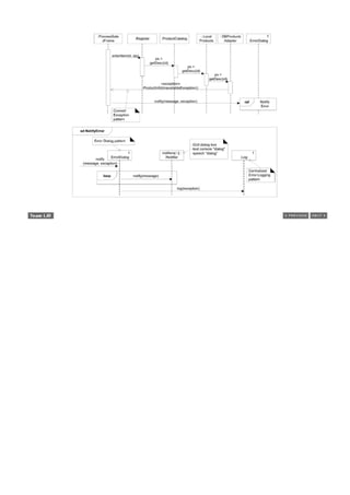
![35.4. Failover to Local Services with a Proxy (GoF)
Failover to a local service for the product information was achieved by inserting the local service in front of the
external service; the local service is always tried first. However, this design is not appropriate for all services;
sometimes the external service should be tried first, and a local version second. For example, consider the
posting of sales to the accounting service. Business wants them posted as soon as possible, for real-time
tracking of store and register activity.
In this case, another GoF pattern can solve the problem: Proxy. Proxy is a simple pattern, and widely used in its
Remote Proxy variant. For example, in Java's RMI and in CORBA, a local client-side object (called a "stub") is
called upon to access a remote object's services. The client-side stub is a local proxy, or a representative for a
remote object.
This NextGen example use of Proxy is not the Remote Proxy variant, but rather the Redirection Proxy (also
known as a Failover Proxy) variant.
Regardless of the variant, the structure of Proxy is always the same; the variations are related to what the
proxy does once called.
A proxy is simply an object that implements the same interface as the subject object, holds a reference to the
real subject, and is used to control access to it. For the general structure, see Figure 35.12.
Figure 35.12. General structure of the Proxy pattern.
[View full size image]
Proxy
Context/Problem
Direct access to a real subject object is not desired or possible. What to do?
Solution
Add a level of indirection with a surrogate proxy object that implements the same interface as the
subject object, and is responsibility for controlling or enhancing access to it.](https://image.slidesharecdn.com/softwaredevleopment-100607174022-phpapp01/85/Software-Development-733-320.jpg)
![Applied to the NextGen case study for external accounting service access, a redirection proxy is used as follows:
1. Send a postSale message to the redirection proxy, treating it as though it was the actual external
accounting service.
2. If the redirection proxy fails to make contact with the external service (via its adapter), then it redirects
the postSale message to a local service, which locally stores the sales for forwarding to the accounting
service, when it is active.
Figure 35.13 illustrates a class diagram of the interesting elements.
Figure 35.13. NextGen use of a redirection proxy.
[View full size image]
Applying UML:
To avoid creating an interaction diagram to show the dynamic behavior, observe how this static diagram
uses numbering to convey the sequence of interaction. An interaction diagram is usually preferred, but this
style is presented to illustrate an alternative style.
Observe the public and private ( +, - ) visibility markers beside Register methods. If absent, they are
unspecified, rather than defaulting to public or private. However, by common convention, unspecified
visibility is interpreted by most readers (and code generating CASE tools) as meaning private attributes
and public methods. However, in this diagram, I especially want to convey the fact that makePayment is
public, and by contrast, completeSaleHandling is private. Visual noise and information overload are always
concerns in communication, so it is desirable to exploit conventional interpretation to keep the diagrams
simple.
To summarize, a proxy is an outer object that wraps an inner object, and both implement the same interface. A
client object (such as a Register) does not know that it references a proxyit is designed as though it is](https://image.slidesharecdn.com/softwaredevleopment-100607174022-phpapp01/85/Software-Development-734-320.jpg)


![Figure 35.14. Standard JavaPOS interfaces.
[View full size image]
Assume that the major manufacturers of POS equipment now provide JavaPOS implementations. For example, if
we buy an IBM POS terminal with a cash drawer, coin dispenser, and so forth, we can also get Java classes from
IBM that implement the JavaPOS interfaces, and that control the physical devices.
Consequently, this part of the architecture is resolved by buying software components, rather than
building them. Encouraging the use of existing components is one of the UP best practices.
How do they work? At a low level, a physical device has a device driver for the underlying operating system. A
Java class (for example, one that implements jpos.CashDrawer) uses JNI (Java Native Interface) to make calls
out to these device drivers.
These Java classes adapt the low-level device driver to the JavaPOS interfaces, and thus can be
characterized as Adapter objects in the GoF pattern sense. They can also be called Proxy
objectslocal proxies that control or enhance access to the physical devices.
It is not uncommon to be able to classify a design in terms of multiple patterns.](https://image.slidesharecdn.com/softwaredevleopment-100607174022-phpapp01/85/Software-Development-738-320.jpg)
![35.7. Abstract Factory (GoF) for Families of Related Objects
The JavaPOS implementations will be purchased from manufacturers. For example[5] :
[5] These are fictitious package names.
// IBM's drivers
com.ibm.pos.jpos.CashDrawer (implements jpos.CashDrawer)
com.ibm.pos.jpos.CoinDispenser (implements jpos.CoinDispenser)
...
// NCR's drivers
com.ncr.posdrivers.CashDrawer (implements jpos.CashDrawer)
com.ncr.posdrivers.CoinDispenser (implements jpos.CoinDispenser)
...
Now, how to design the NextGen POS application to use the IBM Java drivers if IBM hardware is used, NCR
drivers if appropriate, and so forth?
Note that there are families of classes (CashDrawer+CoinDispenser+...) that need to be created, and each
family implements the same interfaces.
For this situation, a commonly used GoF pattern exists: Abstract Factory.
Abstract Factory
Context/Problem
How to create families of related classes that implement a common interface?
Solution
Define a factory interface (the abstract factory). Define a concrete factory class for each family of
things to create. Optionally, define a true abstract class that implements the factory interface and
provides common services to the concrete factories that extend it.
Figure 35.15 illustrates the basic idea; it is improved upon in the next section.
Figure 35.15. A basic abstract factory.
[View full size image]](https://image.slidesharecdn.com/softwaredevleopment-100607174022-phpapp01/85/Software-Development-739-320.jpg)
![An Abstract Class Abstract Factory
A common variation on Abstract Factory is to create an abstract class factory that is accessed using the
Singleton pattern, reads from a system property to decide which of its subclass factories to create, and then
returns the appropriate subclass instance. This is used, for example, in the Java libraries with the
java.awt.Toolkit class, which is an abstract class abstract factory for creating families of GUI widgets for
different operating system and GUI subsystems.
The advantage of this approach is that it solves this problem: How does the application know which abstract
factory to use? IBMJavaPOSDevicesFactory? NCRJavaPOSDevicesFactory?
The following refinement solves this problem. Figure 35.16 illustrates the solution.
Figure 35.16. An abstract class abstract factory.
[View full size image]](https://image.slidesharecdn.com/softwaredevleopment-100607174022-phpapp01/85/Software-Development-740-320.jpg)


![35.8. Handling Payments with Polymorphism and Do It Myself
One of the common ways to apply polymorphism (and Information Expert) is in the context of what Peter Coad
calls the "Do It Myself" strategy or pattern [Coad95]. That is:
Do It Myself
"I (a software object) do those things that are normally done to the actual object that I'm an
abstraction of." [Coad95]
This is the classic object-oriented design style: Circle objects draw themselves, Square objects draw
themselves, Text objects spell-check themselves, and so forth.
Notice that a Text object spell-checking itself is an example of Information Expert: The object that has the
information related to the work does it (a Dictionary is also a candidate, by Expert).
Do It Myself and Information Expert usually lead to the same choice.
Similarly, notice that Circle and Square objects drawing themselves are examples of Polymorphism: When
related alternatives vary by type, assign responsibility using polymorphic operations to the types for which the
behavior varies.
Do It Myself and Polymorphism usually lead to the same choice.
Yet, as was explored in the Pure Fabrication discussion, it is often contraindicated due to problems in coupling
and cohesion, and instead, a designer uses pure fabrications such as strategies, factories, and the like.
Nevertheless, when appropriate, Do It Myself is attractive in part because of its support for low representational
gap. The design for handling payments will be accomplished with Do It Myself and Polymorphism.
One of the requirements for this iteration is to handle multiple payment types, which essentially means to
handle the authorization and accounting steps. Different kinds of payments are authorized in different ways:
Credit and debit payments are authorized with an external authorization service. Both require recording a
receivable entry in accounts receivablemoney owing from the financial institution that does the
authorization.
Cash payments are authorized in some stores (it is a trend in some countries) using a special paper bill
analyzer attached to the POS terminal that checks for counterfeit money. Other stores do not do this.
Check payments are authorized in some stores using a computerized authorization service. Other stores do
not do authorize checks.
CreditPayments are authorized in one way; CheckPayments are authorized in another. This is a classic case for
Polymorphism.
Thus, as shown in Figure 35.17, each Payment subclass has its own authorize method.
Figure 35.17. Classic polymorphism with multiple authorize methods.](https://image.slidesharecdn.com/softwaredevleopment-100607174022-phpapp01/85/Software-Development-743-320.jpg)


![The credit company type can be deduced from the card number. For example, numbers starting with 5 are
MasterCard; numbers starting with 4 are Visa.
The adapter implementations will protect the upper layers of the system against all these variations in
payment authorization. Each adapter is responsible for ensuring the authorization request transaction is in
the appropriate format, and for collaborating with the external service. As discussed in a prior iteration, the
ServicesFactory is responsible for delivering the appropriate ICreditAuthorizationServiceAdapter
implementation.
A Design Scenario
Figure 35.20 starts the presentation of an annotated design that satisfies these details and requirements.
Messages are annotated to illustrate the reasoning.
Figure 35.20. Handling a credit payment.
[View full size image]
Once the correct ICreditAuthorizationServiceAdapter is found, it is given the responsibility for completing the
authorization, as shown in Figure 35.21.](https://image.slidesharecdn.com/softwaredevleopment-100607174022-phpapp01/85/Software-Development-746-320.jpg)
![Figure 35.21. Completing the authorization.
[View full size image]
Once a reply is obtained by CreditPayment (which has been given the responsibility for handling its completion
by Polymorphism and Do It Myself), assuming it is approved, it completes its tasks, as shown in Figure 35.22.
Figure 35.22. Completion of an approved credit payment.
[View full size image]
UML Observe in this sequence diagram that some objects were stacked. This is legal, although few CASE tools
support it. It is helpful in publishing, where width is constrained.](https://image.slidesharecdn.com/softwaredevleopment-100607174022-phpapp01/85/Software-Development-747-320.jpg)

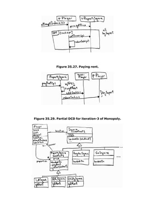


![Introduction
If some package X is widely depended upon by the development team, it is undesirable for X to be very
unstable (going through many new versions), since it increases the impact on the team in terms of constant
version re-synchronization and fixing dependent software that breaks in response to changes in X (version
thrashing).
This soundsand isobvious, but sometimes a team does not pay attention to identifying and stabilizing the most
depended-upon packages, and ends up experiencing more version thrashing than necessary, unaware of the
underlying cause.
[View full size image]
This chapter builds on previous chapter's introduction to layers and packages, by suggesting more fine-grained
heuristics for the organization of packages, to reduce these kinds of change impact. The goal is to create a
robust physical package design.
One feels the pain of fragile dependency-sensitive package organization much more quickly in C++ than in Java
because of the hyper-sensitive compile and link dependencies in C++; a change in one class can have a strong
transitive dependency impact leading to recompilation of many classes, and re-linking.[1] Therefore, these
suggestions are especially helpful for C++ projects and moderately so for Java or C# (as examples) projects.
[1]In C++ the packages may be realized as namespaces, but more likely it means the organization of the source code into separate physical
directoriesone for each "package."
The useful work of Robert Martin [Martin95], who has grappled with physical design and packaging of C++
applications, influenced some of the following guidelines.
Source Code Physical Design in the Implementation Model
This issue is an aspect of physical designthe UP Implementation Model for source code packaging.
While simply diagramming a package design on a whiteboard or CASE tool, we can arbitrarily place types in any
functionally cohesive package without impact. But during source code physical designthe organization of types
into physical units of release as Java or C++ "packages"our choices will influence the degree of developer
impact when changes in those packages occur, if there are many developers sharing a common code base.](https://image.slidesharecdn.com/softwaredevleopment-100607174022-phpapp01/85/Software-Development-753-320.jpg)

![Suppose 1) there is an existing large package P1 with thirty classes, and 2) there is a work trend that a
particular subset of ten classes (C1 through C10) is regularly modified and re-released.
In this case, refactor P1 into P1-a and P1-b, where P1-b contains the ten frequently worked on classes.
Thus, the package has been refactored into more stable and less stable subsets, or more generally, into groups
related to work. That is, if most types in a package are worked on together, then it is a useful grouping.
Ideally, fewer developers have a dependency on P1-b than on P1-a, and by factoring out this unstable part to a
separate package, not as many developers are affected by new releases of P1-b as by re-releasing the larger
original package P1.
Note that this refactoring is in reaction to an emerging work trend. It is difficult to speculatively identify a good
package structure in very early iterations. It incrementally evolves over the elaboration iterations, and it should
be a goal of the elaboration phase (because it is architecturally significant) to have the majority of the package
structure stabilized by elaboration completion.
This guideline illustrates the basic strategy: Reduce widespread dependency on unstable packages.
Guideline: Most Responsible Are Most Stable
If the most responsible (depended-on) packages are unstable, there is a greater chance of widespread change
dependency impact. As an extreme case, if a widely used utility package such as com.foo.util changed
frequently, many things could break. Therefore, Figure 36.1 illustrates an appropriate dependency structure.
Figure 36.1. More responsible packages should be more stable.
[View full size image]
Visually, the lower packages in this diagram should be the most stable.
There are different ways to increase stability in a package:
It contains only or mostly interfaces and abstract classes.
For example, java.sql contains eight interfaces and six classes, and the classes are mostly simple,
stable types such as Time and Date.
It has no dependencies on other packages (it is independent), or it depends on other very stable packages,
or it encapsulates its dependencies such that dependents are not affected.](https://image.slidesharecdn.com/softwaredevleopment-100607174022-phpapp01/85/Software-Development-755-320.jpg)

![Suppose that both Register and PaymentMapper (a class that maps payment objects to/from a relational
database) create instances of CreditPayment from package Payments. One mechanism to increase the long-
term stability of the Sales and Persistence packages is to stop explicitly creating concrete classes defined in
other packages (CreditPayment in Payments).
We can reduce the coupling to this concrete package by using a factory object that creates the instances, but
whose create methods return objects declared in terms of interfaces rather than classes. See Figure 36.4.
Figure 36.4. Reduced coupling to a concrete package by using a factory object.
[View full size image]
Domain Object Factory Pattern
The use of domain object factories with interfaces for the creation of all domain objects is a common design
idiom. I have seen it mentioned informally in design literature as the Domain Object Factory pattern, but don't
know of a published reference.
Guideline: No Cycles in Packages](https://image.slidesharecdn.com/softwaredevleopment-100607174022-phpapp01/85/Software-Development-757-320.jpg)

![36.2. Recommended Resources
Most of the detailed worknot surprisinglyon improving package design to reduce dependency impact comes from
the C++ community, although the principles apply to other languages. Martin's Designing Object-Oriented C++
Applications Using the Booch Method [Martin95] provides good coverage, as does Large-Scale C++ Software
Design [Lakos96]. The subject is also introduced in Java 2 Performance and Idiom Guide [GL99].](https://image.slidesharecdn.com/softwaredevleopment-100607174022-phpapp01/85/Software-Development-759-320.jpg)
![Chapter 37. UML Deployment and Component
Diagrams
Call me paranoid but finding '/*' inside this comment makes me suspicious.
An MPW C compiler warning
Objectives
Summarize UML deployment and component diagram notation.
[View full size image]](https://image.slidesharecdn.com/softwaredevleopment-100607174022-phpapp01/85/Software-Development-760-320.jpg)
![37.1. Deployment Diagrams
A deployment diagram shows the assignment of concrete software artifacts (such as executable files) to
computational nodes (something with processing services). It shows the deployment of software elements to the
physical architecture and the communication (usually on a network) between physical elements. See Figure
37.1. Deployment diagrams are useful to communicate the physical or deployment architecture, for example, in
the UP Software Architecture Document, discussed starting on p. 656.
Figure 37.1. A deployment diagram.
[View full size image]
The basic element of a deployment diagram is a node, of two types:
device node (or device) A physical (e.g., digital electronic) computing resource with processing and
memory services to execute software, such as a typical computer or a mobile phone.
execution environment node (EEN) This is a software computing resource that runs within an outer
node (such as a computer) and which itself provides a service to host and execute other executable
software elements. For example:
an operating system (OS) is software that hosts and executes programs
a virtual machine (VM, such as the Java or .NET VM) hosts and executes programs
a database engine (such as PostgreSQL) receives SQL program requests and executes them, and
hosts/executes internal stored procedures (written in Java or a proprietary language)](https://image.slidesharecdn.com/softwaredevleopment-100607174022-phpapp01/85/Software-Development-761-320.jpg)

![37.2. Component Diagrams
Components are a slightly fuzzy concept in the UML, because both classes and components can be used to
model the same thing. For example, to quote Rumbaugh (one of the UML founders):
The distinction between a structured class and a component is somewhat vague and more a matter of
intent than firm semantics. [RJB04]
And to quote the UML specification [OMG03b]:
A component represents a modular part of a system that encapsulates its contents and whose
manifestation is replaceable within its environment. A component defines its behavior in terms of provided
and required interfaces. As such, a component serves as a type, whose conformance is defined by these
provided and required interfaces.
Again, this idea can be modeled with a regular UML class and its provided and required interfaces. Recall that a
UML class can be used to model any level of software element, from an entire system to subsystem to small
utility object.
But when one uses a UML component, the modeling and design intent is to emphasize 1) that the interfaces are
important, and 2) it is modular, self-contained and replaceable. The second point implies that a component
tends to have little or no dependency on other external elements (except perhaps standard core libraries); it is
a relatively stand-alone module.
UML components are a design-level perspective; they don't exist in the concrete software perspective, but map
to concrete artifacts such as a set of files.
A good analogy for software component modeling is a home entertainment system; we expect to be able to
easily replace the DVD player or speakers. They are modular, self-contained, replaceable, and work via standard
interfaces.
For example, at a large-grained level, a SQL database engine can be modeled as a component; any database
that understands the same version of SQL and supports the same transaction semantics can be substituted. At a
finer level, any solution that implements the standard Java Message Service API can be used or replaced in a
system.
Since the emphasis of component-based modeling is replaceable parts (perhaps to upgrade for better non-
functional qualities, such as performance), it's a general guideline to do component modeling for relatively
large-scale elements, because it is difficult to think about or design for many small, fine-grained replaceable
parts. Figure 37.2 illustrates the essential notation.
Figure 37.2. UML components.
[View full size image]](https://image.slidesharecdn.com/softwaredevleopment-100607174022-phpapp01/85/Software-Development-763-320.jpg)

![Introduction
The point of this chapter is not actually the design of a persistence framework, but, more generally, to introduce
key OO framework design principles and patterns, using persistence as an interesting case study.
[View full size image]
The NextGen applicationlike mostrequires storing and retrieving information in a persistent storage mechanism,
such as a relational database (RDB). This chapter explores the design of a framework for storing persistent
objects.
Caution! Don't Try This at Home!
There are excellent free, robust, industrial-strength open source persistence frameworks, and thus
seldom a need to create one yourself. For example, Hibernate is very widely used in the Java
domain (www.hibernate.org). It solves most or all problems in object-relational mapping,
performance, transaction support, and so forth.
This persistence framework is presented to introduce framework design applied to a common and
problem-rich domain. It is not recommended for an industrial persistence service. At least for Java
technologies, there is no need to create one yourself.](https://image.slidesharecdn.com/softwaredevleopment-100607174022-phpapp01/85/Software-Development-766-320.jpg)


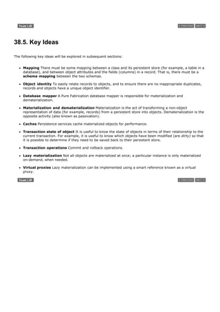
![38.6. Pattern: Representing Objects as Tables
How do you map an object to a record or relational database schema?
The Representing Objects as Tables pattern [BW96] proposes defining a table in an RDB for each persistent
object class. Object attributes containing primitive data types (number, string, boolean, and so on) map to
columns.
If an object has only attributes of primitive data types, the mapping is straightforward. But as we will see,
matters are not that simple, since objects may have attributes that refer to other complex objects, while the
relational model requires that values be atomic (that is, First Normal Form) (see Figure 38.1).
Figure 38.1. Mapping objects and tables.
[View full size image]](https://image.slidesharecdn.com/softwaredevleopment-100607174022-phpapp01/85/Software-Development-772-320.jpg)

![38.8. Pattern: Object Identifier
It is desirable to have a consistent way to relate objects to records, and to be able to ensure that repeated
materialization of a record does not result in duplicate objects.
The Object Identifier pattern [BW96] proposes assigning an object identifier (OID) to each record and
object (or proxy of an object).
An OID is usually an alphanumeric value; each is unique to a specific object. There are various approaches to
generating unique IDs for OIDs, ranging from unique to one database, to globally unique: database sequence
generators, the High-Low key generation strategy [Ambler00], and others.
Within object land, an OID is represented by an OID interface or class that encapsulates the actual value and its
representation. In an RDB, it is usually stored as a fixed length character value.
Every table will have an OID as primary key, and each object will (directly or indirectly) also have an OID. If
every object is associated with an OID, and every table has an OID primary key, every object can be uniquely
mapped to some row in some table (see Figure 38.3).
Figure 38.3. Object identifiers link objects and records.
[View full size image]
This is a simplified view of the design. In reality, the OID may not actually be placed in the persistent
objectalthough that is possible. Instead, it may be placed in a Proxy object wrapping the persistent object. The
design is influenced by the choice of language.
An OID also provides a consistent key type to use in the interface to the persistence service.](https://image.slidesharecdn.com/softwaredevleopment-100607174022-phpapp01/85/Software-Development-774-320.jpg)
![38.9. Accessing a Persistence Service with a Facade
Step one in the design of this subsystem is to define a facade for its services; recall that Facade is a common
pattern to provide a unified interface to a subsystem. To begin, an operation is needed to retrieve an object
given an OID. But in addition to an OID, the subsystem needs to know what type of object to materialize;
therefore, the class type will also be provided. Figure 38.4 illustrates some operations of the facade and its use
in collaboration with one of the NextGen service adapters.
Figure 38.4. The PersistenceFacade.
[View full size image]](https://image.slidesharecdn.com/softwaredevleopment-100607174022-phpapp01/85/Software-Development-775-320.jpg)
![38.10. Mapping Objects: Database Mapper or Database Broker
Pattern
The PersistenceFacadeas true of all facadesdoes not do the work itself, but delegates requests to subsystem
objects.
Who should be responsible for materialization and dematerialization of objects (for example, a
ProductDescription) from a persistent store?
The Information Expert pattern suggests that the persistent object class itself (ProductDescription) is a
candidate, because it has some of the data (the data to be saved) required by the responsibility.
If a persistent object class defines the code to save itself in a database, it is called a direct mapping design.
Direct mapping is workable if the database related code is automatically generated and injected into the class by
a post-processing compiler, and the developer never has to see or maintain this complex database code
cluttering his or her class.
But if direct mapping is manually added and maintained, it has a number of defects and does not tend to scale
well in terms of programming and maintenance. Problems include:
Strong coupling of the persistent object class to persistent storage knowledgeviolation of Low Coupling.
Complex responsibilities in a new and unrelated area to what the object was previously responsible
forviolation of High Cohesion and maintaining a separation of concerns. Technical service concerns are
mixing with application logic concerns.
We will explore a classic indirect mapping approach, that uses other objects to do the mapping for persistent
objects.
Part of this approach is to use the Database Broker pattern [BW95]. It proposes making a class that is
responsible for materialization, dematerialization, and object caching. This has also been called the Database
Mapper pattern in [Fowler01], which is a better name than Database Broker, as it describes its responsibility,
and the term "broker" in distributed systems [BMRSS96] design has a long-standing and different meaning.[1]
[1] In distributed systems, a broker is a front-end server process that delegates tasks to back-end server processes.
A different mapper class is defined for each persistent object class. Figure 38.5 illustrates that each persistent
object may have its own mapper class, and that there may be different kinds of mappers for different storage
mechanisms. A snippet of code:
class PersistenceFacade
{
//...
public Object get( OID oid, Class persistenceClass )
{
// an IMapper is keyed by the Class of the persistent object
IMapper mapper = (IMapper) mappers.get( persistenceClass );
// delegate
return mapper.get( oid );
}
//...
}](https://image.slidesharecdn.com/softwaredevleopment-100607174022-phpapp01/85/Software-Development-776-320.jpg)
![Figure 38.5. Database Mappers.
[View full size image]
Although this diagram indicates two ProductDescription mappers, only one will be active within a running
persistence service.
Metadata-Based Mappers
More flexible, but more involved, is a mapper design based on metadata (data about data). In contrast to
hand-crafting individual mapper classes for different persistent types, metadata-based mappers dynamically
generate the mapping from an object schema to another schema (such as relational) based on reading in
metadata that describes the mapping, such as "TableX maps to Class Y; column Z maps to object property P" (it
gets much more complex). This approach is feasible for languages with reflective programming capabilities, such
as Java, C#, or Smalltalk, and awkward for those that don't, such as C++.
With metadata-based mappers, we can change the schema mapping in an external store and it will be realized
in the running system, without changing source codeProtected Variations with respect to schema variations.
Nevertheless, a useful quality of the framework presented here is that hand-coded or metadata mappers can be
used without affecting clientsencapsulation of the implementation.](https://image.slidesharecdn.com/softwaredevleopment-100607174022-phpapp01/85/Software-Development-777-320.jpg)
![38.11. Framework Design with the Template Method Pattern
The next section describes some of the essential design features of the Database Mappers, which are a central
part of the PFW. These design features are based on the Template Method GoF design pattern [GHJV95].[2]
This pattern is at the heart of framework design, [3] and is familiar to most OO programmers by practice if not
by name.
[2] This pattern is unrelated to C++ templates. It describes the template of an algorithm.
[3] More specifically, of
whitebox frameworks. These are usually class hierarchy and subclassing-oriented frameworks that require the user to know
something about their design and structure; hence, whitebox.
The idea is to define a method (the Template Method) in a superclass that defines the skeleton of an algorithm,
with its varying and unvarying parts. The Template Method invokes other methods, some of which are methods
that may be overridden in a subclass. Thus, subclasses can override the varying methods in order to add their
own unique behavior at points of variability (see Figure 38.6).
Figure 38.6. Template Method pattern in a GUI framework.
[View full size image]](https://image.slidesharecdn.com/softwaredevleopment-100607174022-phpapp01/85/Software-Development-778-320.jpg)
![38.12. Materialization with the Template Method Pattern
If we were to program two or three mapper classes, some commonality in the code would become apparent.
The basic repeating algorithm structure for materializing an object is:
if (object in cache)
return it
else
create the object from its representation in storage
save object in cache
return it
The point of variation is how the object is created from storage.
We will create the get method to be the template method in an abstract superclass AbstractPersistenceMapper
that defines the template, and use a hook method in subclasses for the varying part. Figure 38.7 shows the
essential design.
Figure 38.7. Template Method for mapper objects.
[View full size image]
As shown in this example, it is common for the template method to be public, and the hook method to be
protected. AbstractPersistenceMapper and IMapper are part of the PFW. Now, an application programmer can
plug into this framework by adding a subclass, and overriding or implementing the getObjectFromStorage hook
method. Figure 38.8 shows an example.
Figure 38.8. Overriding the hook method.[4]
[View full size image]](https://image.slidesharecdn.com/softwaredevleopment-100607174022-phpapp01/85/Software-Development-779-320.jpg)
![[4] In Java as an example, the dbRec that is returned from executing a SQL query will be a JDBC ResultSet.
Assume in the hook method implementation of Figure 38.8 that the beginning part of the algorithmdoing a SQL
SELECTis the same for all objects, only the database table name varies.[5] If that assumption held, then once
again, the Template Method pattern could be applied to factor out the varying and unvarying parts of the
algorithm. In Figure 38.9, the tricky part is that AbstractRDBMapper.getObjectFromStorage is a hook method
with respect to AbstractPersistenceMapper.get, but a template method with respect to the new hook method
getObjectFromRecord.
[5]
In many cases, the situation is not so simple. An object may be derived from data from two or more tables or from multiple databases, in which
case, the first version of the Template Method design offers more flexibility.
Figure 38.9. Tightening up the code with the Template Method again.
[View full size image]](https://image.slidesharecdn.com/softwaredevleopment-100607174022-phpapp01/85/Software-Development-780-320.jpg)
![UML In Figure 38.9 observe how constructors can be declared in the UML. The stereotype is optional, and if the
naming convention of constructor name equal to class name is used, probably unnecessary.
Now, IMapper, AbstractPersistenceMapper, and AbstractRDBMapper are part of the framework. The application
programmer needs only to add his or her subclass, such as ProductDescriptionRDBMapper, and ensure it is
created with the table name (to pass via constructor chaining up to the AbstractRDBMapper).
The Database Mapper class hierarchy is an essential part of the framework; new subclasses may be added by
the application programmer to customize it for new kinds of persistent storage mechanisms or for new particular
tables or files within an existing storage mechanism. Figure 38.10 shows some of the package and class
structure. Notice that the NextGen-specific classes do not belong in the general technical services Persistence
package. I think this diagram, combined with Figure 38.9, illustrates the value of a visual language like the UML
to describe parts of software; this succinctly conveys much information.
Figure 38.10. The persistence framework.
[View full size image]](https://image.slidesharecdn.com/softwaredevleopment-100607174022-phpapp01/85/Software-Development-781-320.jpg)
![In Figure 38.10 notice the class ProductDescriptionInMemoryTestDataMapper. Such classes can be used to serve
up hard-coded objects for testing, without accessing any external persistent store.
The UP and the Software Architecture Document
In terms of the UP and documentation, recall that the SAD is a learning aid for future developers, which contains
architectural views of key noteworthy ideas. Including diagrams such as Figure 38.9 and Figure 38.10 in the
SAD for the NextGen project is very much in the spirit of the kind of information an SAD should contain.
Synchronized or Guarded Methods in the UML
The AbstractPersistenceMapper.get method contains critical section code that is not thread safethe same object
could be materializing concurrently on different threads. As a technical service subsystem, the persistence
service needs to be designed with thread safety in mind. Indeed, the entire subsystem may be distributed to a
separate process on another computer, with the PersistenceFacade transformed into a remote server object, and
with many threads simultaneously running in the subsystem, serving multiple clients.
The method should therefore have thread concurrency controlif using Java, add the synchronized keyword.
Figure 38.11 illustrates a synchronized method in a class diagram.
Figure 38.11. Guarded methods in the UML.
[View full size image]](https://image.slidesharecdn.com/softwaredevleopment-100607174022-phpapp01/85/Software-Development-782-320.jpg)
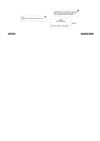

![38.14. Pattern: Cache Management
It is desirable to maintain materialized objects in a local cache to improve performance (materialization is
relatively slow) and support transaction management operations such as a commit.
The Cache Management pattern [BW96] proposes making the Database Mappers responsible for maintaining
its cache. If a different mapper is used for each class of persistent object, each mapper can maintain its own
cache.
When objects are materialized, they are placed in the cache, with their OID as the key. Subsequent requests to
the mapper for an object will cause the mapper to first search the cache, thus avoiding unnecessary
materialization.](https://image.slidesharecdn.com/softwaredevleopment-100607174022-phpapp01/85/Software-Development-785-320.jpg)


![38.16. Transactional States and the State Pattern
Transactional support issues can get complex, but to keep things simple for the presentto focus on the GoF
State patternassume the following:
Persistent objects can be inserted, deleted, or modified.
Operating on a persistent object (for example, modifying it) does not cause an immediate database
update; rather, an explicit commit operation must be performed.
In addition, the response to an operation depends on the transactional state of the object. As an example,
responses may be as shown in the statechart of Figure 38.12.
Figure 38.12. Statechart for PersistentObject.
[View full size image]
For example, an "old dirty" object is one retrieved from the database and then modified. On a commit
operation, it should be updated to the databasein contrast to one in the "old clean" state, which should do
nothing (because it hasn't changed). Within the object-oriented PFW, when a delete or save operation is
performed, it does not immediately cause a database delete or save; rather, the persistent object transitions to
the appropriate state, awaiting a commit or rollback to really do something.
As a UML comment, this is a good example of where a statechart is helpful in succinctly communicating
information that is otherwise awkward to express.
In this design, assume that we will make all persistent object classes extend a PersistentObject class,[6] that
provides common technical services for persistence.[7] For example, see Figure 38.13.
[6] [Ambler00b] is a good reference on a PersistentObject class and persistence layers, although the idea is older.
[7]
Some issues with extending a PersistentObject class are discussed later. Whenever a domain object class extends a technical services class, it
should be pause for reflection, as it mixes architectural concerns (persistence and application logic).
Figure 38.13. Persistent objects.](https://image.slidesharecdn.com/softwaredevleopment-100607174022-phpapp01/85/Software-Development-788-320.jpg)
![Nowand this is the issue that will be resolved with the State patternnotice that commit and rollback methods
require similar structures of case logic, based on a transactional state code. commit and rollback perform
different actions in their cases, but they have similar logic structures.
public void commit() public void rollback()
{ {
switch ( state ) switch ( state )
{ {
case OLD_DIRTY: case OLD_DIRTY:
// ... // ...
break; break;
case OLD_CLEAN: case OLD_CLEAN:
//... //...
break; break;
... ...
} }
An alternative to this repeating case logic structure is the GoF State pattern.
State
Context/Problem
An object's behavior is dependent on its state, and its methods contain case logic reflecting
conditional state-dependent actions. Is there an alternative to conditional logic?
Solution
Create state classes for each state, implementing a common interface. Delegate state-dependent
operations from the context object to its current state object. Ensure the context object always
points to a state object reflecting its current state.
Figure 38.14 illustrates its application in the persistence subsystem.
Figure 38.14. Applying the State pattern.[10]](https://image.slidesharecdn.com/softwaredevleopment-100607174022-phpapp01/85/Software-Development-789-320.jpg)
![[View full size image]
[10] The Deleted class is omitted due to space constraints in the diagram.
State-dependent methods in PersistentObject delegate their execution to an associated state object. If the
context object is referencing the OldDirtyState, then 1) the commit method will cause a database update, and
2) the context object will be reassigned to reference the OldCleanState. On the other hand, if the context object
is referencing the OldCleanState, the inherited do-nothing commit method executes and does nothing (as to be
expected, since the object is clean).
Observe in Figure 38.14 that the state classes and their behavior correspond to the state chart of Figure 38.12.
The State pattern is one mechanism to implement a state transition model in software.[8] It causes an object to
transition to different states in response to events.
[8] There are others, including hard-coded conditional logic, state machine interpreters, and code generators driven by state tables.
As a performance comment, these state objects areironicallystateless (no attributes). Thus, there does not need
to be multiple instances of a classeach is a singleton. Thousands of persistent objects can reference the same
OldDirtyState instance, for example.](https://image.slidesharecdn.com/softwaredevleopment-100607174022-phpapp01/85/Software-Development-790-320.jpg)
![38.17. Designing a Transaction with the Command Pattern
The last section took a simplified view of transactions. This section extends the discussion, but does not cover all
transaction design issues. Informally, a transaction is a unit of worka set of taskswhose tasks must all complete
successfully, or none must be completed. That is, its completion is atomic.
In terms of the persistence service, the tasks of a transaction include inserting, updating, and deleting objects.
One transaction could contain two inserts, one update, and three deletes, for example. To represent this, a
Transaction class is added [Ambler00b].[9] As pointed out in [Fowler01], the order of database tasks within a
transaction can influence its success (and performance).
[9] This is called a UnitOfWork in [Fowler02].
For example:
1. Suppose the database has a referential integrity constraint such that when a record is updated in TableA
that contains a foreign key to a record in TableB, the database requires that the record in TableB already
exists.
2. Suppose a transaction contains an INSERT task to add the TableB record, and an UPDATE task to update
the TableA record. If the UPDATE executes before the INSERT, a referential integrity error is raised.
Ordering the database tasks can help. Some ordering issues are schema-specific, but a general strategy is to
first do inserts, then updates, and then deletes.
Mind that the order in which tasks are added to a transaction by an application may not reflect their best
execution order. The tasks need to be sorted just before their execution.
This leads to another GoF pattern: Command.
Command
Context/Problem
How to handle requests or tasks that need functions such as sorting (prioritizing), queueing,
delaying, logging, or undoing?
Solution
Make each task a class that implements a common interface.
This is a simple pattern with many useful applications; actions become objects, and thus can be sorted, logged,
queued, and so forth. For example, in the PFW, Figure 38.15 shows Command (or task) classes for the database
operations.
Figure 38.15. Commands for database operations.](https://image.slidesharecdn.com/softwaredevleopment-100607174022-phpapp01/85/Software-Development-791-320.jpg)
![[View full size image]
There is much more to completing a transaction solution, but the key idea of this section is to represent each
task or action in the transaction as an object with a polymorphic execute method; this opens up a world of
flexibility by treating the request as an object itself.
The quintessential example of Command is for GUI actions, such as cut and paste. For example, the
CutCommand's execute method does a cut, and its undo method reverses the cut. The CutCommand will also
retain the data necessary to perform the undo. All the GUI commands can be kept in a history stack, so that
they can be popped in turn, and each undone.
Another common use of Command is for server-side request handling. When a server object receives a (remote)
message, it creates a Command object for that request, and hands it off to a CommandProcesser [BMRSS96],
which can queue, log, prioritize, and execute the commands.](https://image.slidesharecdn.com/softwaredevleopment-100607174022-phpapp01/85/Software-Development-792-320.jpg)
![38.18. Lazy Materialization with a Virtual Proxy
It is sometimes desirable to defer the materialization of an object until it is absolutely required, usually for
performance reasons. For example, suppose that ProductDescription objects reference a Manufacturer object,
but only very rarely does it need to be materialized from the database. Only rare scenarios cause a request for
manufacturer information, such as manufacturer rebate scenarios in which the company name and address are
required.
The deferred materialization of "children" objects is known as lazy materialization. Lazy materialization can
be implemented using the Virtual Proxy GoF patternone of many variations of Proxy.
A Virtual Proxy is a proxy for another object (the real subject) that materializes the real subject when it is first
referenced; therefore, it implements lazy materialization. It is a lightweight object that stands for a "real" object
that may or may not be materialized.
A concrete example of the Virtual Proxy pattern with ProductDescription and Manufacturer is shown in Figure
38.16. This design is based on the assumption that proxies know the OID of their real subject, and when
materialization is required, the OID is used to help identify and retrieve the real subject.
Figure 38.16. Manufacturer Virtual Proxy.
[View full size image]
Note that the ProductDescription has attribute visibility to an IManufacturer instance. The Manufacturer for this
ProductDescription may not yet be materialized in memory. When the ProductDescription sends a getAddress
message to the ManufacturerProxy (as though it were the materialized manufacturer object), the proxy
materializes the real Manufacturer, using the OID of the Manufacturer to retrieve and materialize it.](https://image.slidesharecdn.com/softwaredevleopment-100607174022-phpapp01/85/Software-Development-793-320.jpg)


![38.19. How to Represent Relationships in Tables
The code in the prior section relies on a MANU_OID foreign key in the PRODUCT_SPEC table to link to a record
in the MANUFACTURER table. This highlights the question: How are object relationships represented in the
relational model?
The answer is given in the Representing Object Relationships as Tables pattern {BW96], which proposes
the following:
one-to-one associations
Place an OID foreign key in one or both tables representing the objects in relationship.
Or, create an associative table that records the OIDs of each object in relationship.
one-to-many associations, such as a collection
Create an associative table that records the OIDs of each object in relationship.
many-to-many associations
Create an associative table that records the OIDs of each object in relationship.](https://image.slidesharecdn.com/softwaredevleopment-100607174022-phpapp01/85/Software-Development-796-320.jpg)


![Introduction
Once an architecture takes shape, it may be useful to describe it, so that new developers can learn the big ideas
of the system, or so that there is a common view from which to discuss changes. In the UP, the artifact that
describes this is the Software Architecture Document (SAD). The chapter introduces the SAD and its
contents.
[View full size image]](https://image.slidesharecdn.com/softwaredevleopment-100607174022-phpapp01/85/Software-Development-800-320.jpg)
![39.1. The SAD and Its Architectural Views
The Software Architect Document
In addition to the UML package, class, and interaction diagrams, another key artifact in the UP Design Model is
the SAD. It describes the big ideas in the architecture, including the decisions of architectural analysis.
Practically, it is a learning aid for developers who need to understand the essential ideas of the system.
The essence of the SAD is a summary of the architectural decisions (such as with technical memos) and the
N+1 architectural views.
Motivation: Why Create a SAD?
When someone joins the development team, it's useful if the project coach can say, "Welcome to the NextGen
project! Please go to the project website and read the ten page SAD in order to get an introduction to the big
ideas." And later, during a subsequent release, when new people work on the system, a SAD can be a learning
aid to speed their comprehension.
Therefore, it should be written with this audience and goal in mind: What do I need to say (and draw in the
UML) that will quickly help someone understand the major ideas in this system?
Architectural Views
Having an architecture is one thing; a useful description is something else.
In [Kruchten95], the influential and widely adopted idea of describing an architecture with multiple views was
promoted; its multiple-view model is now considered the state of the practice. The essential idea of an
architectural view is this:
Definition: Architectural View
A view of the system architecture from a given perspective; it focuses primarily on structure,
modularity, essential components, and the main control flows. [RUP].
An important aspect of the view missing from this RUP definition is the motivation. That is, an
architectural view should explain why the architecture is the way it is.
An architectural view is a window onto the system from a particular perspective that emphasizes
the key noteworthy information or ideas, and ignores the rest.
An architectural view is a tool of communication, education, or thought; it is expressed in text and UML
diagrams.
For example, the NextGen package and interaction diagrams shown in Chapter 34 on layering and logical
architecture show the big ideas of the logical structure of the software architecture. In the SAD, the architect
will create a section called Logical View, insert those UML diagrams, and add some written commentary on what](https://image.slidesharecdn.com/softwaredevleopment-100607174022-phpapp01/85/Software-Development-801-320.jpg)


![[View full size image]
Discussion and Motivation
A classic layered architecture is used. No application layer of sessions objects was inserted
between the UI and Domain layers, as the system operations are simple, without much workflow
coordination. The primary controller receiving the system operation requests from the UI layer is
the Register class. Note that a facade is placed in front of access to the Jess rule engine as we may
wish to use an alternative in the future.
Figure 2. Deployment view.](https://image.slidesharecdn.com/softwaredevleopment-100607174022-phpapp01/85/Software-Development-808-320.jpg)
![Discussion and Motivation
The product database, inventory system, and tax calculator are deployed to different computers
for performance and reliability goals. The tax calculator is centralized, rather than replicated on
each POS terminal, because of its high licensing cost; there is a chance that in the future it will be
inexpensive enough to replicate locally on each POS terminal.
Data View
Discussion and Motivation
A Process Sale use case scenario is a good example to understand the major data flows. A UML
activity diagram is applied in a data-flow flavor to illustrate the major flows and data stores. See
Figure 3.
Figure 3. A data flow view for a Process Sale scenario.
[View full size image]](https://image.slidesharecdn.com/softwaredevleopment-100607174022-phpapp01/85/Software-Development-809-320.jpg)
![Transformation of data read from the Products database into Java objects is done with the
Hibernate O-R mapping system.
Transformation of sale data written to the ERP databases (inventory and accounting) is done by a
custom NextGen adapter, usually into an XML format required by the ERP system.
Transformation of the payment request data sent to the external payment authorization service is
done by a custom NextGen adapter, usually into the well-known VISA format (and protocol).
Motivation? These external systems and databases were a hard constraint that we had to conform
to.
Use-Case View
The most architecturally significant use case is Process Sale. See the use-case text starting on p.
67. By implementing this use case, most of the key architectural issues were confronted and
resolved. A key system operation is enterItem; see Figure 4 for a partial interaction scenario
across some noteworthy logical boundaries.
Figure 3. A partial use-case realization in a Process Sale scenario.
[View full size image]](https://image.slidesharecdn.com/softwaredevleopment-100607174022-phpapp01/85/Software-Development-810-320.jpg)


![There is a distinction between pure UI layer responsibilities, that encompass creating the content
and pages for display, vs. what is sometimes called the application control layerthe layer of
components that is responsible for deciding the flow of control, and directing the presentation layer
to display something. In common use, web presentation frameworks usually imply the inclusion of
application control responsibilities, which is also true of Struts, as it requires developers to create
subclasses of the Struts Action class that are responsible for flow control decisions.
Architectural Patterns
The Struts architecture is based on the Model-View-Controller (MVC) pattern; specifically, the web
systems variant where the component roles are:
Controller a multithreaded singleton Facade-like object responsible for receiving and delegating
HTTP requests, and by collaboration with other objects, controlling the flow of the application.
View components responsible for generating display content (e.g., HTML).
Model components responsible for domain logic and state.
Struts adoption of MVC provides the architectural foundation to achieve a separation of concerns
related to flow control, display content generation (and formatting), and application logicin this
case through modularization into separate component groups that specialize by cohesively related
responsibilities.
The specific MVC roles mapped to Struts components is illustrated in the UML class diagram in
Figure 2.
Figure 2. MVC roles in Struts.
[View full size image]](https://image.slidesharecdn.com/softwaredevleopment-100607174022-phpapp01/85/Software-Development-813-320.jpg)
![Related Patterns
The ActionServlet acts as a Facade onto the presentation layer. And although not a classic Mediator
that receives and mediates messaging between other decoupled objects, it is similar, because an
Action object returns an ActionForward object to the ActionServlet, which is used to direct the next
step.
The Struts ActionServlet and Action design also illustrates the Command Processor pattern, a
variant of the GoF Command design pattern. The ActionServlet plays the role of Command
Processor, receiving requests and mapping them to Action (Command) objects that execute
requests.
Struts demonstrates the Front Controller and Business Delegate patterns. The ActionServlet is the
Front Controller, or initial point of contact for handling requests. The Action objects are Business
Delegates-abstractions that delegate to the "business" or domain layer of services.
The Action objects also play the role of Adapters, adapting the framework calls to the interface of
the domain layer objects.
As illustrated in the Figure 3, the ActionServlet implements the Template Method pattern: process
is the template, and the processXXX are the hook methods.
Figure 3. Struts framework hotspots.
[View full size image]](https://image.slidesharecdn.com/softwaredevleopment-100607174022-phpapp01/85/Software-Development-814-320.jpg)


![39.6. Recommended Resources
In addition to the original paper [Kruchten95], Documenting Software Architectures: Views and Beyond by
Clements, et al. is a useful resource.](https://image.slidesharecdn.com/softwaredevleopment-100607174022-phpapp01/85/Software-Development-817-320.jpg)


![Introduction
Iterative and agile project planning and management issues are large topics, but a brief exploration of some key
questions related to iterative development and the UP is helpful, such as: What to do in the next iteration? How
to track requirements in iterative development? How to organize project artifacts?
[View full size image]](https://image.slidesharecdn.com/softwaredevleopment-100607174022-phpapp01/85/Software-Development-820-320.jpg)

![40.2. Adaptive versus Predictive Planning
One of the big ideas of iterative development is to adapt based on feedback, rather than to attempt to predict
and plan in detail the entire project. Consequently, in the UP, one creates an Iteration Plan for only the next
iteration.
Beyond the next iteration the detailed plan is left open, to adaptively adjust as the future unfolds (see Figure
40.1). In addition to encouraging flexible, opportunistic behavior, one simple reason for not planning the entire
project in detail is that in iterative development not all the requirements, design details, and thus steps are
known near the start of the project.[1] Another is the preference to trust the planning judgement of the team as
they proceed. Finally, suppose there was a fine-grained detailed plan laid out at the start of the project, and the
team "deviates" from it to exploit better insight in how to best run the project.n From the outside, this might be
viewed as some kind of failure, when it in fact it is just the opposite.
[1] They aren't really or reliably known on a "waterfall" project either, although detailed planning for the entire project may occur as though they were.
Figure 40.1. Milestones are important, but avoid detailed predictive planning into
the far future.
[View full size image]
However, there are still goals and milestones; adaptive development doesn't mean the team doesn't know
where they are going, or the milestone dates and objectives. In iterative development, the team still does
commit to dates and objectives, but the detailed path to these is flexible. For example, the NextGen team may
set a milestone that in three months, use cases Process Sale, Handle Returns, and Authenticate User, and the
logging and pluggable rules features will be completed. Butand this is the key pointthe fine-grained plan or path
of two-week timeboxed iterations to that milestone is not defined in detail. The order of steps, or what to do in
each iteration over the following three months, is not fixed. Rather, just the next two-week iteration is planned,
and the team adapts step by step, working to fulfill the objectives by the milestone date. Of course,
dependencies in components and resources naturally constrain some ordering of the work, but not all activities
need to be planned and scheduled in fine-grained detail.](https://image.slidesharecdn.com/softwaredevleopment-100607174022-phpapp01/85/Software-Development-822-320.jpg)

![40.3. Phase and Iteration Plans
At a macro level, it is possible to establish milestone dates and objectives, but at the micro level, the plan to the
milestone is left flexible except for the near future (for example, the next four weeks). These two levels are
reflected in the UP Phase Plan and Iteration Plan, both of which are part of the composite Software
Development Plan. The Phase Plan lays out the macro-level milestone dates and objectives, such as the end of
phases and mid-phase pilot test milestones. The Iteration Plan defines the work for the current and next
iterationnot all iterations (see Figure 40.2).
Figure 40.2. Phase and Iteration Plans.
[View full size image]
During inception, the milestone estimates in the Phase Plan are vague "guesstimates." As elaboration
progresses, the estimates improve. One goal of the elaboration phase is, at its completion, to have enough
realistic information for the team to commit to major milestone dates and objectives for the end of construction
and transition (that is, project delivery).](https://image.slidesharecdn.com/softwaredevleopment-100607174022-phpapp01/85/Software-Development-824-320.jpg)


![40.5. The (In)Validity of Early Estimates
Garbage in, garbage out. Estimates done with unreliable and fuzzy information are unreliable and fuzzy. In the
UP it is understood that estimates done during inception are not dependable (this is true of all methods, but the
UP acknowledges it). Early inception estimates merely provide guidance if the project is worthy of some real
investigation in elaboration, to generate a good estimate. After the first elaboration iteration there is some
realistic information to produce a rough estimate. After the second iteration, the estimate starts to develop
credibility (see Figure 40.4).
Figure 40.4. Estimation and project phases.
[View full size image]
Useful estimates require investment in some elaboration iterations.
This is not to imply that it is impossible or worthless to attempt early, accurate estimates. If possible, very
good. However, most organizations do not find this to be the case, for reasons that include continuous
introduction of new technologies, novel applications, and many other complications. Thus, the UP advocates
some realistic work in elaboration before generating estimates used for project planning and budgeting.](https://image.slidesharecdn.com/softwaredevleopment-100607174022-phpapp01/85/Software-Development-827-320.jpg)


![40.8. Recommended Resources
Agile and Iterative Development: A Manager's Guide by Larman provides many practice tips, in addition to the
wide-spread evidence of the failure of the waterfall, and the advantage of iterative methods.
Organizational Patterns of Agile Software Development by Coplien and Harrison summarizes many successful
iterative and agile process and project management tips.
Software Project Management: A Unified Framework by Royce provides an iterative and UP perspective on
project planning and management.
Cockburn's Surviving Object-Oriented Projects: A Manager's Guide contains more useful information on iterative
planning, and the transition to iterative and object technology projects.
Planning Extreme Programming by Beck and Fowler is another good resource.
Kruchten's The Rational Unified Process: An Introduction contains useful chapters specifically on planning and
project management in the UP.
As a caution, there are some books that purport to discuss planning for "iterative development" or the "Unified
Process" that actually belie a waterfall or predictive approach to planning.
Rapid Development [McConnell96] is an excellent overview of many practices and issues in planning and project
management, and project risks.](https://image.slidesharecdn.com/softwaredevleopment-100607174022-phpapp01/85/Software-Development-830-320.jpg)


![relationships, and behavior" [RJB99]. May be used to represent software or conceptual elements.
class attribute
A characteristic or property that is the same for all instances of a class. This information is usually stored
in the class definition.
class hierarchy
A description of the inheritance relations between classes.
class method
A method that defines the behavior of the class itself, as opposed to the behavior of its instances.
classification
Defines a relation between a class and its instances. The classification mapping identifies the extension of
a class.
collaboration
Two or more objects that participate in a client/server relationship in order to provide a service.
composition
The definition of a class in which each instance is comprised of other objects.
concept
A category of ideas or things. In this book, used to designate real-world things rather than software
entities. A concept's intension is a description of its attributes, operations and semantics. A concept's
extension is the set of instances or example objects that are members of the concept. Often defined as a
synonym for domain class.
concrete class
A class that can have instances.
constraint
A restriction or condition on an element.
constructor](https://image.slidesharecdn.com/softwaredevleopment-100607174022-phpapp01/85/Software-Development-839-320.jpg)


![The specification of a logical software solution in terms of software objects, such as their classes,
attributes, methods, and collaborations.
object-oriented programming language
A programming language that supports the concepts of encapsulation, inheritance, and polymorphism.
OID
Object Identifier.
operation
In the UML, "a specification of a transformation or query that an object may be called to execute"
[RJB99]. An operation has a signature, specified by its name and parameters, and it is invoked via a
message. A method is an implementation of an operation with a specific algorithm.
pattern
A named description of a problem, solution, when to apply the solution, and how to apply the solution in
new contexts.
persistence
The enduring storage of the state of an object.
persistent object
An object that can survive the process or thread that created it. A persistent object exists until it is
explicitly deleted.
polymorphic operation
The same operation implemented differently by two or more classes.
polymorphism
The concept that two or more classes of objects can respond to the same message in different ways, using
polymorphic operations. Also, the ability to define polymorphic operations.
postcondition
A constraint that must hold true after the completion of an operation.](https://image.slidesharecdn.com/softwaredevleopment-100607174022-phpapp01/85/Software-Development-843-320.jpg)


![Inside Front Cover
Sample Unified Process Artifacts and Timing (s-start; r-refine)
Discipline Artifact Incep. Elab. Const. Trans.
Iteration I1 E1..En C1..Cn T1..T2
Business Domain Model s
Modeling
Requirements Use-Case Model s r
Vision s r
Supplementary Specification s r
Glossary s r
Design Design Model s r
SW Architecture Document s
Data Model s r
Implementation Implementation Model (code, s r r
html, …)
[View full size image]](https://image.slidesharecdn.com/softwaredevleopment-100607174022-phpapp01/85/Software-Development-846-320.jpg)


![Inside Back Cover
[View full size image]
[View full size image]](https://image.slidesharecdn.com/softwaredevleopment-100607174022-phpapp01/85/Software-Development-850-320.jpg)

![Index
[SYMBOL] [A] [B] [C] [D] [E] [F] [G] [H] [I] [J] [K] [L] [M] [N] [O] [P] [Q] [R] [S] [T] [U] [V] [W] [X]](https://image.slidesharecdn.com/softwaredevleopment-100607174022-phpapp01/85/Software-Development-852-320.jpg)
![Index
[SYMBOL] [A] [B] [C] [D] [E] [F] [G] [H] [I] [J] [K] [L] [M] [N] [O] [P] [Q] [R] [S] [T] [U] [V] [W] [X]
.NET 2nd 3rd
4+1 view model 2nd](https://image.slidesharecdn.com/softwaredevleopment-100607174022-phpapp01/85/Software-Development-853-320.jpg)
![Index
[SYMBOL] [A] [B] [C] [D] [E] [F] [G] [H] [I] [J] [K] [L] [M] [N] [O] [P] [Q] [R] [S] [T] [U] [V] [W] [X]
Abbot83
abstract class 2nd
in UML 2nd
Abstract Factory
abstract operation
in UML 2nd
abstract use case
action
activation bar
active class 2nd
active object 2nd 3rd
activity diagram 2nd
actor 2nd
in use case
offstage
supporting
Adapter
adaptive development
adaptive vs. predictive planning
addition use case
aggregation 2nd
agile methods 2nd 3rd 4th 5th
agile modeling 2nd
agile UP
analysis
analysis and design
definition
analysis object models
architectural
analysis 2nd
baseline
decisions
design principles
factors
patterns-promotion of
proof-of-concept 2nd
prototype
synthesis 2nd
view
data
deployment
implementation
logical
process
security
use case
architectural analysis
architectural approach documents
architectural factors
architectural view
architecturally significant requirements
architecture 2nd
cross-cutting concerns](https://image.slidesharecdn.com/softwaredevleopment-100607174022-phpapp01/85/Software-Development-854-320.jpg)

![Index
[SYMBOL] [A] [B] [C] [D] [E] [F] [G] [H] [I] [J] [K] [L] [M] [N] [O] [P] [Q] [R] [S] [T] [U] [V] [W] [X]
base use case
behavioral decomposition
benefits of iterative development
black-box use cases
BMRSS96 2nd 3rd
Booch Method
Booch94
boundary objects
brief use case
Business Modeling discipline 2nd
Business Object Model 2nd
business rules
Business Rules artifact 2nd
business use case](https://image.slidesharecdn.com/softwaredevleopment-100607174022-phpapp01/85/Software-Development-856-320.jpg)
![Index
[SYMBOL] [A] [B] [C] [D] [E] [F] [G] [H] [I] [J] [K] [L] [M] [N] [O] [P] [Q] [R] [S] [T] [U] [V] [W] [X]
CASE tools
casual use case
class
abstract
association
conceptual 2nd
definitions
design
hierarchy 2nd 3rd
in UML 2nd
mapping from DCD
partition
partitioning
UML meaning
UML notation
class diagram 2nd 3rd
class diagrams
class hierarchy 2nd
class method calls 2nd
class operation
in UML
classifier
in the UML
classifier name
in UML
client-driven development
Coad95
COCOMO II
code
mapping OO designs
code smells
cohesion 2nd
collaboration
in RDD
collaboration diagram
conditional messages
example 2nd
instance creation
iteration
links
message sequencing
message to self
messages
mutually exclusive conditionals
sequence number
collaborations
of objects in RDD
collection
in OO programming
in UML
iteration over in UML
n UML
Command pattern 2nd](https://image.slidesharecdn.com/softwaredevleopment-100607174022-phpapp01/85/Software-Development-857-320.jpg)

![Index
[SYMBOL] [A] [B] [C] [D] [E] [F] [G] [H] [I] [J] [K] [L] [M] [N] [O] [P] [Q] [R] [S] [T] [U] [V] [W] [X]
data dictionary 2nd
data flow diagrams
data holder objects
data model 2nd 3rd
data modeling
data type 2nd 3rd
data view
data-driven design
Database Broker pattern
Database Mapper pattern
database mapping
datastore node
decision symbol
activity diagrams
delegate
delegation
Delegation Event Model
dependency 2nd
deployment architecture
deployment diagram
deployment view
derived attributes
description class
design
Design by Contract
design class
design class diagram 2nd
Design discipline
Development Case
device node
diagram fragment
diagram frames
discipline
and phases
Do It Myself 2nd
documenting architecture
domain layer 2nd 3rd 4th
Domain Model
domain model
Domain Model
domain vocabulary
finding concepts
map-maker strategy
modeling changing states
modeling the unreal
multiple meanings
organizing in packages
domain object models
Domain Objects
domain objects 2nd 3rd
domain rules 2nd](https://image.slidesharecdn.com/softwaredevleopment-100607174022-phpapp01/85/Software-Development-859-320.jpg)

![Index
[SYMBOL] [A] [B] [C] [D] [E] [F] [G] [H] [I] [J] [K] [L] [M] [N] [O] [P] [Q] [R] [S] [T] [U] [V] [W] [X]
eager initialization
EBP
Eclipse
EJBs
in Controller pattern
elaboration phase 2nd 3rd
elementary business process 2nd
entity objects
Environment discipline
error definition
essential use case style
estimates
estimation 2nd
event
evolution point 2nd 3rd
evolutionary development 2nd 3rd
exceptions
in class diagrams 2nd
exceptions in UML
executable architecture
execution environment node
execution specification
Expert 2nd
application 2nd 3rd 4th
extend use case relationship
extension point
Extreme Programming 2nd 3rd](https://image.slidesharecdn.com/softwaredevleopment-100607174022-phpapp01/85/Software-Development-861-320.jpg)
![Index
[SYMBOL] [A] [B] [C] [D] [E] [F] [G] [H] [I] [J] [K] [L] [M] [N] [O] [P] [Q] [R] [S] [T] [U] [V] [W] [X]
Facade
factor table
Factory
failure definition
fault definition
feature of system
features 2nd 3rd
final class
in UML
final operation
in UML 2nd
fixture
in testing
focus of control
fork
formal specifications
forward engineering
found message
Fowler96
frames
opt, loop, alt, ref operators
framework
persistence
frameworks
fully dressed use case
function points
functional requirements
Fusion method](https://image.slidesharecdn.com/softwaredevleopment-100607174022-phpapp01/85/Software-Development-862-320.jpg)
![Index
[SYMBOL] [A] [B] [C] [D] [E] [F] [G] [H] [I] [J] [K] [L] [M] [N] [O] [P] [Q] [R] [S] [T] [U] [V] [W] [X]
Gang of Four patterns 2nd
generalization 2nd 3rd 4th 5th
abstract class notation
and conceptual class sets
and conceptual classes
conformance
in UML
overview
partitioning
subclass validity tests
UML notation
generalize
use case relationship
generics
GHJV95 2nd 3rd 4th 5th 6th
Glossary artifact 2nd 3rd 4th
GoF design patterns
GRASP patterns 2nd 3rd
Controller
Creator
Expert
High Cohesion
Indirection
Low Coupling
Polymorphism
Protected Variations
Pure Fabrication
guarded methods 2nd](https://image.slidesharecdn.com/softwaredevleopment-100607174022-phpapp01/85/Software-Development-863-320.jpg)
![Index
[SYMBOL] [A] [B] [C] [D] [E] [F] [G] [H] [I] [J] [K] [L] [M] [N] [O] [P] [Q] [R] [S] [T] [U] [V] [W] [X]
Hibernate
High Cohesion
Hollywood Principle](https://image.slidesharecdn.com/softwaredevleopment-100607174022-phpapp01/85/Software-Development-864-320.jpg)
![Index
[SYMBOL] [A] [B] [C] [D] [E] [F] [G] [H] [I] [J] [K] [L] [M] [N] [O] [P] [Q] [R] [S] [T] [U] [V] [W] [X]
IDEs
implementation
Implementation Model 2nd 3rd
implementation view
inception phase 2nd 3rd 4th
include use case relationship
Indirection
Information Expert 2nd
information hiding
inheritance
in UML
initial domain object
instance
in UML
UML notation
interaction diagram 2nd
class
instance
message syntax
interaction fragment
interaction frames 2nd
interaction occurrence
interaction overview diagram 2nd
interaction use
interface
in UML 2nd
when to use
interface realization
interface implementation
issue cards
iteration over a collection in UML
Iteration Plan 2nd 3rd 4th
iterations
iterative development 2nd 3rd 4th
benefits
planning
iterative lifecycle](https://image.slidesharecdn.com/softwaredevleopment-100607174022-phpapp01/85/Software-Development-865-320.jpg)
![Index
[SYMBOL] [A] [B] [C] [D] [E] [F] [G] [H] [I] [J] [K] [L] [M] [N] [O] [P] [Q] [R] [S] [T] [U] [V] [W] [X]
join
JUnit](https://image.slidesharecdn.com/softwaredevleopment-100607174022-phpapp01/85/Software-Development-866-320.jpg)
![Index
[SYMBOL] [A] [B] [C] [D] [E] [F] [G] [H] [I] [J] [K] [L] [M] [N] [O] [P] [Q] [R] [S] [T] [U] [V] [W] [X]
keyword
in UML](https://image.slidesharecdn.com/softwaredevleopment-100607174022-phpapp01/85/Software-Development-867-320.jpg)
![Index
[SYMBOL] [A] [B] [C] [D] [E] [F] [G] [H] [I] [J] [K] [L] [M] [N] [O] [P] [Q] [R] [S] [T] [U] [V] [W] [X]
Law of Demeter
layer
layered architecture 2nd 3rd
Layers pattern
lazy initialization
lazy materialization
lifeline
UML interaction diagrams
link
Liskov Substitution Principle
logical
logical architecture 2nd 3rd
logical view
lollipop notation
looping
sequence diagrams 2nd
Low Coupling 2nd
low representational gap 2nd 3rd
lower representational gap
LRG
low representational gap 2nd
LSP](https://image.slidesharecdn.com/softwaredevleopment-100607174022-phpapp01/85/Software-Development-868-320.jpg)
![Index
[SYMBOL] [A] [B] [C] [D] [E] [F] [G] [H] [I] [J] [K] [L] [M] [N] [O] [P] [Q] [R] [S] [T] [U] [V] [W] [X]
MDA 2nd
merge symbol
activity diagrams
message
asynchronous
UML notation 2nd
metaclass
metadata 2nd
method 2nd
from collaboration diagram
in note symbols
in UML
MO95 2nd 3rd
Model Driven Architecture 2nd
Model-View Separation 2nd
Model-View-Controller
modular designs
Moment-Interval
multiplicity 2nd
MVC](https://image.slidesharecdn.com/softwaredevleopment-100607174022-phpapp01/85/Software-Development-869-320.jpg)
![Index
[SYMBOL] [A] [B] [C] [D] [E] [F] [G] [H] [I] [J] [K] [L] [M] [N] [O] [P] [Q] [R] [S] [T] [U] [V] [W] [X]
N+1 view model 2nd
namespace
in UML packages
navigability arrow
in UML class diagrams
navigation model
node
non-functional requirements
Supplementary Specification
note
in UML
NUnit](https://image.slidesharecdn.com/softwaredevleopment-100607174022-phpapp01/85/Software-Development-870-320.jpg)
![Index
[SYMBOL] [A] [B] [C] [D] [E] [F] [G] [H] [I] [J] [K] [L] [M] [N] [O] [P] [Q] [R] [S] [T] [U] [V] [W] [X]
object
active
in UML
persistent
Object Constraint Language
object databases
object design 2nd 3rd 4th
introduction
object node
object-oriented analysis
object-oriented analysis and design
definition
dice game example
object-relational mapping
Observer
OCL 2nd
offstage actor
Open-Closed Principle
operation
in UML 2nd
operation contracts
operations
ordered
keyword in UML
organizing artifacts](https://image.slidesharecdn.com/softwaredevleopment-100607174022-phpapp01/85/Software-Development-871-320.jpg)
![Index
[SYMBOL] [A] [B] [C] [D] [E] [F] [G] [H] [I] [J] [K] [L] [M] [N] [O] [P] [Q] [R] [S] [T] [U] [V] [W] [X]
package
dependencies
design
organization guidelines
ownership
reference
package attributes
in UML
package diagram 2nd 3rd
package name
in UML classifier name
parameterized types
parameters
in class diagrams 2nd
participants
in interaction diagrams
partition
path name
pattern 2nd 3rd 4th 5th
Abstract Factory
Adapter
Coarse-Grained Remote Interface
Command
Composite
Controller
Convert Exceptions
Creator
Do It Myself 2nd 3rd
Expert
Facade
Factory
High Cohesion
Indirection
Layers
Low Coupling
Model-View Separation
names
Observer
Polymorphism
Protected Variations
Proxy
Publish-Subscribe
Pure Fabrication
Redirection Proxy
Remote Proxy
Singleton
State
Strategy
Template Method
Virtual Proxy
patterns
architectural
history](https://image.slidesharecdn.com/softwaredevleopment-100607174022-phpapp01/85/Software-Development-872-320.jpg)

![Index
[SYMBOL] [A] [B] [C] [D] [E] [F] [G] [H] [I] [J] [K] [L] [M] [N] [O] [P] [Q] [R] [S] [T] [U] [V] [W] [X]
qualified association 2nd
qualifier 2nd
quality attributes 2nd
quality scenario](https://image.slidesharecdn.com/softwaredevleopment-100607174022-phpapp01/85/Software-Development-874-320.jpg)
![Index
[SYMBOL] [A] [B] [C] [D] [E] [F] [G] [H] [I] [J] [K] [L] [M] [N] [O] [P] [Q] [R] [S] [T] [U] [V] [W] [X]
r - refine 2nd 3rd 4th
rake symbol
activity diagrams
Rational Unified Process
RDD 2nd 3rd
read-only attributes
in UML
Redirection Proxy
ref
tag in frames
ref frames
refactoring
reference
in interaction diagrams
reference attribute
reflexive association
relational cohesion
relational databases
Remote Proxy
replicates
representational decomposition
required interface
in UML
requirements
functional in Use-Case Model
in the UP
non-functional in Supplementary Specification
overview 2nd
various types
Requirements discipline
responsibilities 2nd 3rd
and interaction diagrams
and methods
doing
importance of
knowing
patterns
responsibility-driven design
return in sequence diagram
return type
in class diagrams
in UML operations
reverse engineering
risk-driven development
role
of objects in RDD
versus concept
rolename
in DCDs
round-trip engineering
rules
business or domain
domain or business](https://image.slidesharecdn.com/softwaredevleopment-100607174022-phpapp01/85/Software-Development-875-320.jpg)

![Index
[SYMBOL] [A] [B] [C] [D] [E] [F] [G] [H] [I] [J] [K] [L] [M] [N] [O] [P] [Q] [R] [S] [T] [U] [V] [W] [X]
SAD
scenario
schema mapping
Scrum 2nd
sd frames
frame tag
security view
selector
in lifeline box
separation of concerns 2nd 3rd
sequence diagram 2nd
activation box
conditional message
conditional messages
instance creation
iteration over collection
lifelines
looping
loops
message to class
message to self
messages
mutually exclusive conditional
object destruction
return
strength and weaknesses
Servlet
Session objects
in EJB and Controller pattern
Singleton
UML shorthand notation
socket notation
software architecture
Software Architecture Document 2nd 3rd
software development process
specialization 2nd
state
modeling
state machine diagram
example
guard conditions
nested states
overview
transition actions
State pattern 2nd
state-independent
statechart diagram
nested states
static method calls 2nd
static operation
in UML
stereotype 2nd 3rd
Strategy](https://image.slidesharecdn.com/softwaredevleopment-100607174022-phpapp01/85/Software-Development-877-320.jpg)

![Index
[SYMBOL] [A] [B] [C] [D] [E] [F] [G] [H] [I] [J] [K] [L] [M] [N] [O] [P] [Q] [R] [S] [T] [U] [V] [W] [X]
tagged value
tags
in stereotypes
technical memos
Template Method
templates
templatized types
test fixture
test-driven development 2nd 3rd 4th
test-first development [See test-driven development]
testing
threads
threads in the UML
three-tier architecture
tier
time intervals
timeboxing
transition
transition phase](https://image.slidesharecdn.com/softwaredevleopment-100607174022-phpapp01/85/Software-Development-879-320.jpg)
![Index
[SYMBOL] [A] [B] [C] [D] [E] [F] [G] [H] [I] [J] [K] [L] [M] [N] [O] [P] [Q] [R] [S] [T] [U] [V] [W] [X]
UI modeling
navigation modeling
UML
class diagrams
constraint
Data Modeling Profile
meta-model
overview
profiles 2nd 3rd
stereotype
tagged value
UML 2
Unified Process
unique
keyword in UML
unit testing
UP
agile
phases
use
use case 2nd
abstract
actor
addition
and development process
base
black-box
brief
business
casual
concrete
essential style
extend
fully dressed
include
instance
postcondition
precondition
subfunction level
system
user goal level
when create abstract use cases
use cases
relating them
use-case driven development
Use-Case Model 2nd
use-case realizations 2nd 3rd
use-case view 2nd](https://image.slidesharecdn.com/softwaredevleopment-100607174022-phpapp01/85/Software-Development-880-320.jpg)
![Index
[SYMBOL] [A] [B] [C] [D] [E] [F] [G] [H] [I] [J] [K] [L] [M] [N] [O] [P] [Q] [R] [S] [T] [U] [V] [W] [X]
value objects 2nd
variation point 2nd
VDM
version thrashing
virtual proxy
Virtual Proxy
visibility 2nd 3rd 4th
attribute
global
in class diagrams
in UML 2nd
local
parameter
Vision artifact 2nd 3rd 4th
visual modeling](https://image.slidesharecdn.com/softwaredevleopment-100607174022-phpapp01/85/Software-Development-881-320.jpg)
![Index
[SYMBOL] [A] [B] [C] [D] [E] [F] [G] [H] [I] [J] [K] [L] [M] [N] [O] [P] [Q] [R] [S] [T] [U] [V] [W] [X]
waterfall 2nd
WebForms 2nd
WinForms
Wirfs-Brock93](https://image.slidesharecdn.com/softwaredevleopment-100607174022-phpapp01/85/Software-Development-882-320.jpg)
![Index
[SYMBOL] [A] [B] [C] [D] [E] [F] [G] [H] [I] [J] [K] [L] [M] [N] [O] [P] [Q] [R] [S] [T] [U] [V] [W] [X]
XML
XP 2nd 3rd
xUnit](https://image.slidesharecdn.com/softwaredevleopment-100607174022-phpapp01/85/Software-Development-883-320.jpg)