This document describes Edition 3.1 of the Association of Geotechnical and Geoenvironmental Specialists' (AGS) format for the electronic transfer of geotechnical and geoenvironmental data. The AGS format was created to standardize the electronic transfer of subsurface investigation data between different software programs and users. This updated edition includes new groups, fields, pick lists, and determinand codes added based on user suggestions. It aims to incorporate commonly used additions to the format while maintaining compatibility with previous versions.


![A6/19
b) Group DREM may be used for all remarks and notes that are related to a specific depth in the borehole or
trial pit, that are not geological.
• DREM is used for reporting incidents during drilling (such as "Fishing for broken U100 3.00 to 3.70m"),
drilling records that don't readily fit in any other groups (such as "Pushing boulder ahead of casing 7.80
to 8.15m"), observations that are not strictly geological (such as "Strong petrol smell at 5.00m").
13 Reporting trial pits
Simple trial pits where the geology is treated as horizontal, continuous layers can be reported in a borehole type
log, which is a one dimensional record of the ground conditions, the only dimension being depth. These logs
readily convert into the AGS Format.
For more complex trial pits where the geology is not in horizontal, continuous layers, the log will normally include
a (two dimensional) sketch of the faces to show the disposition of the strata, and the location of the samples and
in situ tests. The stratum descriptions will be referenced to the sketch. Such trial pit logs require some
compromises to convert them to a one dimensional borehole log in order to report them in the AGS Format. The
following procedure may be used, but alternative methods are possible.
• On the face sketch give each stratum a stratum code number or letter. This is used to link the sketch to
the stratum description, and is recorded as GEOL_STAT.
• In your log production software produce a (one dimensional) borehole style log. The stratum code
GEOL_STAT should be prominently displayed at the start of, or adjacent to, each stratum description.
The strata should be presented in the same vertical sequence that they are seen in the trial pit faces.
The stratum boundary depths on this log should be "approximate average depths" for each stratum
boundary, as seen in the trial pit faces. This may be difficult to achieve where the strata boundaries are
complex. However, every stratum must be included in the depth log, with some nominal thickness, and
there must be no gaps in the log. Where strata are very limited in extent they could be included as a
detail in the DETL Group, rather than as a separate stratum in the GEOL Group.
• Samples are recorded in the SAMP Group as normal, but also include the stratum code in
GEOL_STAT of the SAMP Group to indicate which stratum the sample has been taken from. If you
also wish to indicate which face of the trial pit the sample was taken from, then include this as a remark
in SAMP_REM.
• In situ CBR, density, redox, resistivity and vane tests can be carried out in a trial pit, rather than at the
ground surface. The tests should be recorded in the relevant Group as normal, but also include the
stratum code in GEOL_STAT of the Group to indicate which stratum the test was carried out in. If
required, the trial pit face number should be given in the REM field of the Group.
• If the face sketch has been produced on computer software, then this could be included in the AGS file
as an associated file (see Section 9 above), and referenced in the FILE_FSET field of the HOLE Group
for the trial pit.
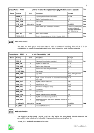
14 Reporting SPT tests
The following guidelines may be applied to the reporting of SPT tests in the ISPT Group, but alternative usages
are possible.
• When full test penetration of 450mm has been achieved the N value should be reported in the
ISPT_NVAL field as a number. That is, report 35, do not report N=35.
• When full test penetration has not been achieved, then leave the ISPT_NVAL field empty.
• In the ISPT_REP field put the test result as reported on the paper borehole log. This may be in a
format specific to the Provider. For example, an N Value of 35 may be reported on the log as: 35,
N=35, [35] or 3,5/9,7,9,10=35 etc. An incomplete test may be reported on the log as: 50/160mm,
50/160, (50) or 8,10/15,12,23 for 10mm etc.
AGS Format Edition 3.1](https://image.slidesharecdn.com/ags31amay2005-1272466846-phpapp01/85/A-G-S3-1a-May2005-131-320.jpg)