The document provides a comprehensive overview of structural welding, detailing various welding positions, joint types, and processes, as well as the AWS D1.1:2020 code requirements for welded steel structures. It outlines the responsibilities of engineers, contractors, and inspectors in the welding process and includes sections on design, pre-qualification of welding procedures, and fabrication practices. The content emphasizes safety, various welding techniques, and specific criteria for different types of joints and loads.

![SECTION 1. GENERAL REQUIREMENTS
• 1.2 Standard Unit of Measurements
• This standard makes use of both U.S. Customary Units and the
International System of Units (SI). The latter are shown within
brackets ([ ]) or in appropriate columns in tables and figures. The
measurements may not be exact equivalents; therefore, each
system must be used independently.](https://image.slidesharecdn.com/structuralwelding-240819090740-0ed5e824/85/Structural-Welding-and-AWS-D1-1-2020-pptx-16-320.jpg)
![SECTION 1. GENERAL REQUIREMENTS
• 1.4 Limitations
• The code was specifically developed for welded steel structures that utilize carbon or low alloy steels
that are 1/8 in [3 mm] or thicker with a minimum specified yield strength of 100 ksi [690 MPa] or less.
The code may be suitable to govern structural fabrications outside the scope of the intended
purpose.
However,
• the Engineer should evaluate such suitability, and based upon such evaluations, incorporate into
contract documents any necessary changes to code requirements to address the specific
requirements of the application that is outside the scope of the code.
• The Structural Welding Committee encourages the Engineer to consider the applicability of other
AWS DI codes for applications involving
• aluminum (AWS D l.2),
• sheet steel equal to or less than 3/16 in [5 mm] thick (AWS D l.3),
• reinforcing steel (AWS D l.4),
• stainless steel (AWS D l.6),
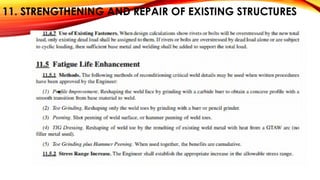
• strengthening and repair of existing structures (AWS D l.7),
• seismic supplement (AWS D l.8),
• and titanium (AWS D l.9).
• The AASHTO/AWS D l.5 Bridge Welding Code was specifically developed for welding highway bridge
components and is recommended for those applications.](https://image.slidesharecdn.com/structuralwelding-240819090740-0ed5e824/85/Structural-Welding-and-AWS-D1-1-2020-pptx-18-320.jpg)
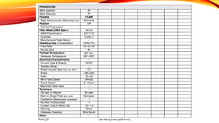
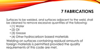
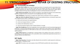
![7. FABRICATION
• Baking Electrodes.
• Electrodes exposed to the atmosphere for periods greater than those allowed,
shall be baked as follows:
• (1) All electrodes having low-hydrogen coverings conforming to AWS A5.1 shall
be baked for at least two hours between 500°F and 800°F [260°C and 430°C], or
• (2) All electrodes having low-hydrogen coverings conforming to A WS A5.5 shall
be baked for at least one hour at temperatures between 700°F and 800°F [370°C
and 430°C].
• All electrodes shall be placed in a suitable oven at a temperature not exceeding
one half the final baking temperature for a minimum of one half hour prior to
increasing the oven temperature to the final baking temperature. Final baking
time shall start after the oven reaches final baking temperature.](https://image.slidesharecdn.com/structuralwelding-240819090740-0ed5e824/85/Structural-Welding-and-AWS-D1-1-2020-pptx-63-320.jpg)