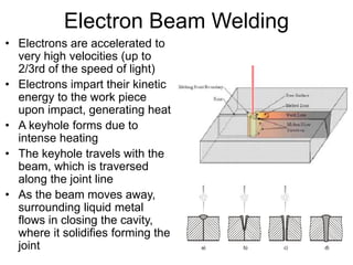
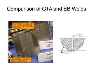
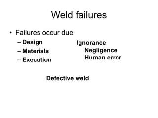
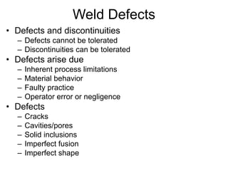
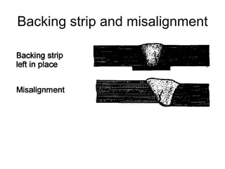
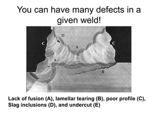
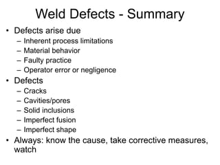
Welding Processes and
Weld Defects
Dr. G.D. Janaki Ram
IIT Madras
Welding Processes
• Fusion welding
– Base materials melt
– Filler material may be added
– 90% welding is fusion welding
• Solid-state welding
– No base material melting
– Plastic deformation of base materials
– Material can get red hot
– Several metallurgical advantages
– Numerous established applications
Fusion Welding Processes
• Heat sources
– Fuel burning (Oxy-acetylene gas welding)
– Electric arc (MMAW, SAW, GTAW, GMAW, FCAW,
PAW)
– Laser beam (LBW)
– Electron beam (EBW)
• Electric arc processes dominate
Thermal Diffusivity
• A measure of the energy input required
to create and sustain a molten puddle
•  = k/Cp
– Cu = 1.14 cm2/s, Fe = 0.028 cm2/s
Heat Input and Energy Density
• Heat input = heat utilized for melting + heat conducted
sideways (wasted)
• Peak temperature decreases as a function of distance away
from weld center line
• HAZ shows inferior properties
• HAZ width increases with heat input
Heat Input and Energy Density
• Concentrated heat sources  higher
melting efficiency
• Energy density
– Fuel burning < electric arc < laser/electron
beam
– Energy density within arc welding processes:
• MMAW < GTAW < PAW
• High energy density processes produce
narrow HAZs
• Always: Use lowest heat input consistent
with penetration
Need for Edge Preparation
• Beyond a certain thickness, through-
thickness melting not possible with electric
arcs
– Prepare plate edges to facilitate access
– Use filler metal to fill the groove
– Weld progressively in multiple passes
Joint Types and Welding Positions
Joint Types
Welding Positions
Arc Welding Processes
• Consumable electrode processes (MMAW,
SAW, FCAW, GMAW)
– With flux shielding (MMAW, SAW, FCAW)
– With inert gas (GMAW) or CO2 shielding (CO2
Welding)
• Non-consumable electrode processes (GTAW,
PAW)
– Inert gas shielding
MMAW
• Arc striking
• Polarity
– DCEN (straight)
– DCEP (reverse)
• Most heat generates at
anode
• DCEN good for
penetration
• DCSP good for filling
Arc forces due to interaction between magnetic field and electric current
Spray-type metal transfer due to arc forces (important for out-of-position
welding)
MMAW
• Flux coating on electrodes
– Slag formers to protect the weld metal
– CO2 formers for additional protection
– Ionizing elements for greater arc stability
– Alloying elements
– Iron powder to increase deposition rate
• Slag removal is important
• Simple, inexpensive, and portable equipment
– Field applications, out-of-position welding
• Best used for steels
• Problems
– Flux protection won’t work for most non-ferrous metals
– Unavoidable interruptions (for changing electrodes)
– Low energy density
– Manual welding
– Time consuming for thick sections
– Large current  electrode overheating  flux disintegration
SAW
• Search for: Continuous automatic welding, Better
protection, Thick section welding  SAW
• Slow cooling rates (soft and ductile welds)
• Large currents  deep penetration
• Large heat inputs
• Restricted to horizontal position
FCAW
• Idea
– Tubular “flux-cored” wire
Versatile and
continuous process,
but many
disadvantages of
MMAW remain
GTAW
• Non-consumable electrode
• Inert gas shielding (Ar or He)
• Good for welding NFMs
• Precise process – good
for root passes and
thinner gauges
• Filler addition possible,
but cumbersome
• Manual or automatic
• Slow process
• Out-of-position welding
difficult
GMAW
• Consumable electrode
• Inert gas shielding
• Good for welding NFMs
• Fast process
• Out-of-position welding
• Semi-automatic or automatic
• For ferrous materials, CO2
shielding is adequate
PAW
• Arc constriction
• Strong directional arc
• Plasma gas and shielding gas
• Automatic
• Keyhole welding
• Variable polarity
Laser Beam Welding
• High energy density
• Rapid cooling rates
• Precision welding/micro-
joining
• Thick section welding
• Several metallurgical
advantages
Electron Beam Welding
• Electrons are accelerated to
very high velocities (up to
2/3rd of the speed of light)
• Electrons impart their kinetic
energy to the work piece
upon impact, generating heat
• A keyhole forms due to
intense heating
• The keyhole travels with the
beam, which is traversed
along the joint line
• As the beam moves away,
surrounding liquid metal
flows in closing the cavity,
where it solidifies forming the
joint
Comparison of GTA and EB Welds
Weld failures
• Failures occur due
– Design
– Materials
– Execution
Defective weld
Ignorance
Negligence
Human error
Weld Defects
• Defects and discontinuities
– Defects cannot be tolerated
– Discontinuities can be tolerated
• Defects arise due
– Inherent process limitations
– Material behavior
– Faulty practice
– Operator error or negligence
• Defects
– Cracks
– Cavities/pores
– Solid inclusions
– Imperfect fusion
– Imperfect shape
Weld Cracking
Cause: Embrittlement + residual stresses
Solidification cracks
Steel
Al Al
HAZ Liquation Cracking
• Occurs in PMZ/HAZ
– Grain boundary
melting
– Stresses
Al-Cu alloy 2219
• Low melting fillers
– PMZ solidification precedes WM
solidification
• Fine grained base metals
• Low heat inputs and high energy density
processes
– Minimize HAZ/PMZ width
Cold Cracking/Hydrogen-Induced
Cracking/Delayed Cracking
• H in weld metal
• Stresses
• Susceptible
microstructure
• Low temperature
• High strength steels are
more susceptible
• Control measures
– Minimize stresses
– Clean surfaces
– Bake electrodes
– Stress relieve
Reheat Cracking
• Cr-Mo-V steels
• Cause: Carbide precipitation near dislocations in
HAZ during stress relieving (550-650˚C)
• Remedies: Low HI, Low restraint, rapid heating
through critical temperature range
Lamellar tearing
Susceptible steel with
elongated inclusions
Gas Porosity
• Gas porosity – CO boil in steels and H porosity in Al
alloys
– Causes: Porous oxide layers, wet or contaminated (oil,
grease, etc.) plate surfaces, insufficient shielding gas, etc.
– Remedies: Remove oxide/anodized layers, check shielding
gas, and always clean part surfaces just prior to welding
H Gas Porosity in an Al
alloy weld Vapor porosity
Wormhole porosity
Solid inclusions
• Slag inclusions
• Oxide inclusions
• W inclusions
Slag inclusions
Incomplete Fusion and Lack of
Penetration
Fillet weld
Butt weld
Imperfect Shape
Are these really dangerous?
Effect of undercut on
fatigue life of EB welded
carbon steel
Backing strip and misalignment
You can have many defects in a
given weld!
Lack of fusion (A), lamellar tearing (B), poor profile (C),
Slag inclusions (D), and undercut (E)
Weld Defects - Summary
• Defects arise due
– Inherent process limitations
– Material behavior
– Faulty practice
– Operator error or negligence
• Defects
– Cracks
– Cavities/pores
– Solid inclusions
– Imperfect fusion
– Imperfect shape
• Always: know the cause, take corrective measures,
watch

FUSION WELDING.ppt

  • 1.
    Welding Processes and WeldDefects Dr. G.D. Janaki Ram IIT Madras
  • 2.
    Welding Processes • Fusionwelding – Base materials melt – Filler material may be added – 90% welding is fusion welding • Solid-state welding – No base material melting – Plastic deformation of base materials – Material can get red hot – Several metallurgical advantages – Numerous established applications
  • 3.
    Fusion Welding Processes •Heat sources – Fuel burning (Oxy-acetylene gas welding) – Electric arc (MMAW, SAW, GTAW, GMAW, FCAW, PAW) – Laser beam (LBW) – Electron beam (EBW) • Electric arc processes dominate
  • 4.
    Thermal Diffusivity • Ameasure of the energy input required to create and sustain a molten puddle •  = k/Cp – Cu = 1.14 cm2/s, Fe = 0.028 cm2/s
  • 5.
    Heat Input andEnergy Density • Heat input = heat utilized for melting + heat conducted sideways (wasted) • Peak temperature decreases as a function of distance away from weld center line • HAZ shows inferior properties • HAZ width increases with heat input
  • 6.
    Heat Input andEnergy Density • Concentrated heat sources  higher melting efficiency • Energy density – Fuel burning < electric arc < laser/electron beam – Energy density within arc welding processes: • MMAW < GTAW < PAW • High energy density processes produce narrow HAZs • Always: Use lowest heat input consistent with penetration
  • 7.
    Need for EdgePreparation • Beyond a certain thickness, through- thickness melting not possible with electric arcs – Prepare plate edges to facilitate access – Use filler metal to fill the groove – Weld progressively in multiple passes
  • 8.
    Joint Types andWelding Positions Joint Types Welding Positions
  • 9.
    Arc Welding Processes •Consumable electrode processes (MMAW, SAW, FCAW, GMAW) – With flux shielding (MMAW, SAW, FCAW) – With inert gas (GMAW) or CO2 shielding (CO2 Welding) • Non-consumable electrode processes (GTAW, PAW) – Inert gas shielding
  • 10.
    MMAW • Arc striking •Polarity – DCEN (straight) – DCEP (reverse) • Most heat generates at anode • DCEN good for penetration • DCSP good for filling Arc forces due to interaction between magnetic field and electric current Spray-type metal transfer due to arc forces (important for out-of-position welding)
  • 11.
    MMAW • Flux coatingon electrodes – Slag formers to protect the weld metal – CO2 formers for additional protection – Ionizing elements for greater arc stability – Alloying elements – Iron powder to increase deposition rate • Slag removal is important • Simple, inexpensive, and portable equipment – Field applications, out-of-position welding • Best used for steels • Problems – Flux protection won’t work for most non-ferrous metals – Unavoidable interruptions (for changing electrodes) – Low energy density – Manual welding – Time consuming for thick sections – Large current  electrode overheating  flux disintegration
  • 12.
    SAW • Search for:Continuous automatic welding, Better protection, Thick section welding  SAW • Slow cooling rates (soft and ductile welds) • Large currents  deep penetration • Large heat inputs • Restricted to horizontal position
  • 13.
    FCAW • Idea – Tubular“flux-cored” wire Versatile and continuous process, but many disadvantages of MMAW remain
  • 14.
    GTAW • Non-consumable electrode •Inert gas shielding (Ar or He) • Good for welding NFMs • Precise process – good for root passes and thinner gauges • Filler addition possible, but cumbersome • Manual or automatic • Slow process • Out-of-position welding difficult
  • 15.
    GMAW • Consumable electrode •Inert gas shielding • Good for welding NFMs • Fast process • Out-of-position welding • Semi-automatic or automatic • For ferrous materials, CO2 shielding is adequate
  • 16.
    PAW • Arc constriction •Strong directional arc • Plasma gas and shielding gas • Automatic • Keyhole welding • Variable polarity
  • 17.
    Laser Beam Welding •High energy density • Rapid cooling rates • Precision welding/micro- joining • Thick section welding • Several metallurgical advantages
  • 18.
    Electron Beam Welding •Electrons are accelerated to very high velocities (up to 2/3rd of the speed of light) • Electrons impart their kinetic energy to the work piece upon impact, generating heat • A keyhole forms due to intense heating • The keyhole travels with the beam, which is traversed along the joint line • As the beam moves away, surrounding liquid metal flows in closing the cavity, where it solidifies forming the joint
  • 19.
    Comparison of GTAand EB Welds
  • 20.
    Weld failures • Failuresoccur due – Design – Materials – Execution Defective weld Ignorance Negligence Human error
  • 21.
    Weld Defects • Defectsand discontinuities – Defects cannot be tolerated – Discontinuities can be tolerated • Defects arise due – Inherent process limitations – Material behavior – Faulty practice – Operator error or negligence • Defects – Cracks – Cavities/pores – Solid inclusions – Imperfect fusion – Imperfect shape
  • 22.
  • 23.
  • 24.
    HAZ Liquation Cracking •Occurs in PMZ/HAZ – Grain boundary melting – Stresses Al-Cu alloy 2219 • Low melting fillers – PMZ solidification precedes WM solidification • Fine grained base metals • Low heat inputs and high energy density processes – Minimize HAZ/PMZ width
  • 25.
    Cold Cracking/Hydrogen-Induced Cracking/Delayed Cracking •H in weld metal • Stresses • Susceptible microstructure • Low temperature • High strength steels are more susceptible • Control measures – Minimize stresses – Clean surfaces – Bake electrodes – Stress relieve
  • 26.
    Reheat Cracking • Cr-Mo-Vsteels • Cause: Carbide precipitation near dislocations in HAZ during stress relieving (550-650˚C) • Remedies: Low HI, Low restraint, rapid heating through critical temperature range
  • 27.
    Lamellar tearing Susceptible steelwith elongated inclusions
  • 28.
    Gas Porosity • Gasporosity – CO boil in steels and H porosity in Al alloys – Causes: Porous oxide layers, wet or contaminated (oil, grease, etc.) plate surfaces, insufficient shielding gas, etc. – Remedies: Remove oxide/anodized layers, check shielding gas, and always clean part surfaces just prior to welding H Gas Porosity in an Al alloy weld Vapor porosity
  • 29.
  • 30.
    Solid inclusions • Slaginclusions • Oxide inclusions • W inclusions Slag inclusions
  • 31.
    Incomplete Fusion andLack of Penetration Fillet weld Butt weld
  • 32.
  • 33.
    Are these reallydangerous? Effect of undercut on fatigue life of EB welded carbon steel
  • 34.
    Backing strip andmisalignment
  • 35.
    You can havemany defects in a given weld! Lack of fusion (A), lamellar tearing (B), poor profile (C), Slag inclusions (D), and undercut (E)
  • 36.
    Weld Defects -Summary • Defects arise due – Inherent process limitations – Material behavior – Faulty practice – Operator error or negligence • Defects – Cracks – Cavities/pores – Solid inclusions – Imperfect fusion – Imperfect shape • Always: know the cause, take corrective measures, watch