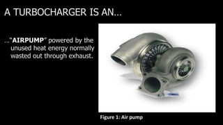
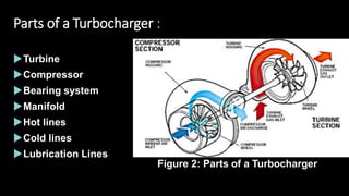
TURBOCHARGE
R
Group members :
 Afrasiab UW-15-EE-BSC-062
 Farmanullah UW-15-EE-BSC-090
 Ibadullah UW-15-EE-BSC-058
 Ihsan Elahi UW-15-EE-BSC-096
CONTENTS :
WHAT IS A TURBOCHARGER
WHY WE USE
TECHNOLOGY BEHIND
PARTS of a Turbocharger
Turbocharger Design and Operation
Turbocharger Size and Response Time
BOOST CONTROL
TURBOCHARGER FAILURES
Maintenance / Problem
Additional technologies commonly used in turbocharger
installations
Applications
Advantages of Turbochargers
The Disadvantages of Turbocharger
Conclusion
References
TURBOCHARGER :
It is a turbine driven compressor.
It uses the waste energy from exhaust gas to increase
the charge mass of air and power of the engine.
Increase amount of air
Locate at exhaust side
Convert exhaust to mechanical work
Compressor wheel is driven by shaft
High Compress air in the turbocharger passed to intake.
A TURBOCHARGER IS AN…
…“AIRPUMP” powered by the
unused heat energy normally
wasted out through exhaust.
Figure 1: Air pump
WHY WE USE ?
It uses some of the unused energy contained in the hot
exhaust gases.
Wide range of power levels.
Increases the density of the air to add more fuel.
Reduces specific fuel oil consumption.
Improves mechanical, thermal efficiencies.
Parts of a Turbocharger :
Turbine
Compressor
Bearing system
Manifold
Hot lines
Cold lines
Lubrication Lines
Figure 2: Parts of a Turbocharger
TURBOCHARGERS Turbocharger Design and Operation :
A turbocharger consists of two chambers connected by a
center housing.
The two chambers contain a turbine wheel and a compressor
wheel connected by a shaft which passes through the center
housing.
FIGURE 3. The exhaust drives the turbine wheel on the left, which is connected
to the impeller wheel on the right through a shaft. The bushings that support the
shaft are lubricated with engine oil under pressure.
Figure 4 : Working of turbocharger
The air is pressurized by
the compressor.
The air cooler brings the
air to a high density to
the engine by decreasing
the temperature.
A part of the exhaust
gas energy is treated
by the turbine
The turbine power is
transmitted to the
compressor through
the rotating shaft
The engine can work
at a high power
density without
increase of the
thermal load
Turbocharging Principles :
Figure 5: working of a Turbocharger
Intercooler :
An intercooler is an intake air cooling device commonly used on
turbocharged engines.
The air compressed by the turbocharger, reducing its temperature and
thereby increasing the density of the air supplied to the engine.
These intercoolers also known as heat exchangers.
There are two types of intercoolers;
Air-to-Air.
Air-to-Water.
Figure 6 :Air to air Intercooler Circuit
An Air-to-Air intercooler extracts heat
from the Compressed air by passing it
through its network of tubes with
cooling fans.
As the compressed air is pushed
through the intercooler it transfers the
heat to the tubes and, in turn to the
cooling fans.
The cool air from outside, traveling at
speed, absorbs the heat from the
cooling fans reducing the temperature
of the compressed air.
Air to-Air intercooler :
Air-to-Water intercooler :
An Air-to-Water intercooler uses water as a
heat transfer agent. In this setup cool water is
pumped through the air/water intercooler,
extracting heat from the compressed air as it
passes through.
The heated water is then pumped through
another cooling circuit (usually a dedicated
radiator) while the cooled compressed air is
pushed into the engine.
Water is more efficient at heat transfer than air
and has more stability so it can handle a wider
range of temperatures. Figure 7: Air-to-Water intercooler
Figure 8: Graph of torque vs engine speed of
turbocharged engine .
BOOST CONTROL :
Turbocharged systems is designed to provide a pressure greater
than atmospheric pressure in the intake valve.
This increased pressure forces additional amounts of air into
the combustion chamber over what would normally be
forced in by atmospheric pressure.
This increased charge increases engine power.
BOOST CONTROL Wastegate :
 A turbocharger uses exhaust gases
to increase boost, which causes the
engine to make more exhaust gases,
which in turn increases the boost
from the turbocharger.
 To prevent overboost and severe
engine damage, most turbocharger
systems use a wastegate.
 A wastegate is a valve similar to a
door that can open and close.
 The wastegate is a bypass valve at
the exhaust inlet to the turbine.
 It allows all of the exhaust into the
turbine, or it can route part of the
exhaust past the turbine to the exhaust
system. FIGURE 9: A wastegate in the diesel Engine
BOOST CONTROL Relief Valves :
A relief valve vents pressurized
air from the connecting pipe
between the outlet of the
turbocharger and the throttle
whenever the throttle is closed
during boost, such as during
shifts.
FIGURE 10: A blow-off valve is used in
some turbocharged systems to relieve
boost pressure during deceleration.
Turbocharger Size and Response Time :
Turbocharger response time is directly related to the size of
the turbine and compressor wheels.
Small wheels accelerate rapidly; large wheels accelerate slowly.
While small wheels would seem to have an advantage over larger ones,
they may not have enough airflow capacity for an engine.
To minimize turbo lag, the intake and exhaust breathing capacities of an
engine must be matched to the exhaust and intake airflow capabilities of
the turbocharger.
TURBOCHARGER FAILURES :
When turbochargers fail to function correctly, a drop in
power is noticed.
To restore proper operation, the turbocharger must be
rebuilt, repaired, or replaced.
It is not possible to simply remove turbocharger, seal any
openings, and still maintain decent drivability.
Maintenance/Problem :
LACK OF OIL
DIRTY OIL
MECHANICAL DAMAGE OF VANE
WHEELS
WASTEGATE CONTROL PROBLEMS
Additional technologies commonly used in turbocharger
installations :
 Intercooling
 Water injection
 Fuel-air mixture ratio
 Wastegate
 blow off valves
 Free floating
Applications :
 Petrol-powered cars
 Diesel-powered cars
 Motorcycles
 Trucks
 Aircraft
 Marine and land-based Diesel
turbochargers.
Advantages of Turbochargers:
1. Safety
2. Petrol Consumption
3. Noise Pollution
4. Driving Pleasure
Safety :
Vehicles become more responsive and safer to drive with a
turbocharged engine as it can generate as much as seven times
more power as compared to a non-turbocharged engine.
Additionally, turbochargers are also able to prevent the loss of
power at higher altitudes where regular engines will produce
lesser power due to lower air pressure.
Petrol Consumption :
As the overall turbocharged engine size is smaller, less petrol
will then be required to produce the same amount of power
as a non-turbocharged engine. This advantage can then be
translated into a significant petrol cost savings.
Noise Pollution :
Turbocharger has the ability to silence any generated
noise with its role as an additional silencer. Furthermore,
all thanks to its smaller engine size, the sound-radiating
outer surface is also smaller, thus will be less noisy.
Driving Pleasure :
Driving is made a real pleasure with a turbocharged
engine as turbochargers deliver more power output
and a greater torque, which in turns improve your
vehicle’s performance on the road.
The Disadvantages of Turbocharger :
Installation
System
Cost
Driving
Installation :
Installation is a key component in the effectiveness of a turbocharger,
and not all mechanics are capable of installing one properly
If the mechanic even makes a minor mistake, it will not only make
the turbocharger ineffective, but may cause damage within the
engine.
System :
The system in some vehicles may not be able to handle a turbocharger
and can cause the system to malfunction and break down.
 A professional mechanic needs to make the modifications to the engine
and increase fuel ratio to ensure the maximum benefit of turbocharger.
Cost :
 Turbochargers are quite expensive, and it’s important to determine
whether the advantages are worth the cost.
 Turbochargers often cost between $2,000 and $5,000 as of 2010.
Driving :
 Turbocharged vehicles travel at high speeds, any malfunctions could
lead to dangerous situations
 Driving at fast speeds can be dangerous on commercial roads and lead
to accidents or suspension of license.
Conclusion :
It’s a forced induction device.
Increasing the efficiency of an engine.
Half's the fuel consumption in an engine.
 www.wikepedia.org
 www.superchevy.com
 www.explara.com
 www. Turbobygarrett.com
 www.bufkinengineering.com/Umluft.htm
References:
THANK YOU

Turbocharger presentation

  • 2.
  • 3.
    Group members : Afrasiab UW-15-EE-BSC-062  Farmanullah UW-15-EE-BSC-090  Ibadullah UW-15-EE-BSC-058  Ihsan Elahi UW-15-EE-BSC-096
  • 4.
    CONTENTS : WHAT ISA TURBOCHARGER WHY WE USE TECHNOLOGY BEHIND PARTS of a Turbocharger Turbocharger Design and Operation Turbocharger Size and Response Time BOOST CONTROL
  • 5.
    TURBOCHARGER FAILURES Maintenance /Problem Additional technologies commonly used in turbocharger installations Applications Advantages of Turbochargers The Disadvantages of Turbocharger Conclusion References
  • 6.
    TURBOCHARGER : It isa turbine driven compressor. It uses the waste energy from exhaust gas to increase the charge mass of air and power of the engine. Increase amount of air Locate at exhaust side Convert exhaust to mechanical work Compressor wheel is driven by shaft High Compress air in the turbocharger passed to intake.
  • 7.
    A TURBOCHARGER ISAN… …“AIRPUMP” powered by the unused heat energy normally wasted out through exhaust. Figure 1: Air pump
  • 8.
    WHY WE USE? It uses some of the unused energy contained in the hot exhaust gases. Wide range of power levels. Increases the density of the air to add more fuel. Reduces specific fuel oil consumption. Improves mechanical, thermal efficiencies.
  • 9.
    Parts of aTurbocharger : Turbine Compressor Bearing system Manifold Hot lines Cold lines Lubrication Lines Figure 2: Parts of a Turbocharger
  • 10.
    TURBOCHARGERS Turbocharger Designand Operation : A turbocharger consists of two chambers connected by a center housing. The two chambers contain a turbine wheel and a compressor wheel connected by a shaft which passes through the center housing.
  • 11.
    FIGURE 3. Theexhaust drives the turbine wheel on the left, which is connected to the impeller wheel on the right through a shaft. The bushings that support the shaft are lubricated with engine oil under pressure.
  • 12.
    Figure 4 :Working of turbocharger
  • 13.
    The air ispressurized by the compressor. The air cooler brings the air to a high density to the engine by decreasing the temperature. A part of the exhaust gas energy is treated by the turbine The turbine power is transmitted to the compressor through the rotating shaft The engine can work at a high power density without increase of the thermal load Turbocharging Principles : Figure 5: working of a Turbocharger
  • 14.
    Intercooler : An intercooleris an intake air cooling device commonly used on turbocharged engines. The air compressed by the turbocharger, reducing its temperature and thereby increasing the density of the air supplied to the engine. These intercoolers also known as heat exchangers. There are two types of intercoolers; Air-to-Air. Air-to-Water.
  • 15.
    Figure 6 :Airto air Intercooler Circuit An Air-to-Air intercooler extracts heat from the Compressed air by passing it through its network of tubes with cooling fans. As the compressed air is pushed through the intercooler it transfers the heat to the tubes and, in turn to the cooling fans. The cool air from outside, traveling at speed, absorbs the heat from the cooling fans reducing the temperature of the compressed air. Air to-Air intercooler :
  • 16.
    Air-to-Water intercooler : AnAir-to-Water intercooler uses water as a heat transfer agent. In this setup cool water is pumped through the air/water intercooler, extracting heat from the compressed air as it passes through. The heated water is then pumped through another cooling circuit (usually a dedicated radiator) while the cooled compressed air is pushed into the engine. Water is more efficient at heat transfer than air and has more stability so it can handle a wider range of temperatures. Figure 7: Air-to-Water intercooler
  • 17.
    Figure 8: Graphof torque vs engine speed of turbocharged engine .
  • 18.
    BOOST CONTROL : Turbochargedsystems is designed to provide a pressure greater than atmospheric pressure in the intake valve. This increased pressure forces additional amounts of air into the combustion chamber over what would normally be forced in by atmospheric pressure. This increased charge increases engine power.
  • 19.
    BOOST CONTROL Wastegate:  A turbocharger uses exhaust gases to increase boost, which causes the engine to make more exhaust gases, which in turn increases the boost from the turbocharger.  To prevent overboost and severe engine damage, most turbocharger systems use a wastegate.  A wastegate is a valve similar to a door that can open and close.  The wastegate is a bypass valve at the exhaust inlet to the turbine.  It allows all of the exhaust into the turbine, or it can route part of the exhaust past the turbine to the exhaust system. FIGURE 9: A wastegate in the diesel Engine
  • 20.
    BOOST CONTROL ReliefValves : A relief valve vents pressurized air from the connecting pipe between the outlet of the turbocharger and the throttle whenever the throttle is closed during boost, such as during shifts. FIGURE 10: A blow-off valve is used in some turbocharged systems to relieve boost pressure during deceleration.
  • 21.
    Turbocharger Size andResponse Time : Turbocharger response time is directly related to the size of the turbine and compressor wheels. Small wheels accelerate rapidly; large wheels accelerate slowly. While small wheels would seem to have an advantage over larger ones, they may not have enough airflow capacity for an engine. To minimize turbo lag, the intake and exhaust breathing capacities of an engine must be matched to the exhaust and intake airflow capabilities of the turbocharger.
  • 22.
    TURBOCHARGER FAILURES : Whenturbochargers fail to function correctly, a drop in power is noticed. To restore proper operation, the turbocharger must be rebuilt, repaired, or replaced. It is not possible to simply remove turbocharger, seal any openings, and still maintain decent drivability.
  • 23.
    Maintenance/Problem : LACK OFOIL DIRTY OIL MECHANICAL DAMAGE OF VANE WHEELS WASTEGATE CONTROL PROBLEMS
  • 24.
    Additional technologies commonlyused in turbocharger installations :  Intercooling  Water injection  Fuel-air mixture ratio  Wastegate  blow off valves  Free floating
  • 26.
    Applications :  Petrol-poweredcars  Diesel-powered cars  Motorcycles  Trucks  Aircraft  Marine and land-based Diesel turbochargers.
  • 27.
    Advantages of Turbochargers: 1.Safety 2. Petrol Consumption 3. Noise Pollution 4. Driving Pleasure
  • 28.
    Safety : Vehicles becomemore responsive and safer to drive with a turbocharged engine as it can generate as much as seven times more power as compared to a non-turbocharged engine. Additionally, turbochargers are also able to prevent the loss of power at higher altitudes where regular engines will produce lesser power due to lower air pressure.
  • 29.
    Petrol Consumption : Asthe overall turbocharged engine size is smaller, less petrol will then be required to produce the same amount of power as a non-turbocharged engine. This advantage can then be translated into a significant petrol cost savings.
  • 30.
    Noise Pollution : Turbochargerhas the ability to silence any generated noise with its role as an additional silencer. Furthermore, all thanks to its smaller engine size, the sound-radiating outer surface is also smaller, thus will be less noisy.
  • 31.
    Driving Pleasure : Drivingis made a real pleasure with a turbocharged engine as turbochargers deliver more power output and a greater torque, which in turns improve your vehicle’s performance on the road.
  • 32.
    The Disadvantages ofTurbocharger : Installation System Cost Driving
  • 33.
    Installation : Installation isa key component in the effectiveness of a turbocharger, and not all mechanics are capable of installing one properly If the mechanic even makes a minor mistake, it will not only make the turbocharger ineffective, but may cause damage within the engine.
  • 34.
    System : The systemin some vehicles may not be able to handle a turbocharger and can cause the system to malfunction and break down.  A professional mechanic needs to make the modifications to the engine and increase fuel ratio to ensure the maximum benefit of turbocharger.
  • 35.
    Cost :  Turbochargersare quite expensive, and it’s important to determine whether the advantages are worth the cost.  Turbochargers often cost between $2,000 and $5,000 as of 2010.
  • 36.
    Driving :  Turbochargedvehicles travel at high speeds, any malfunctions could lead to dangerous situations  Driving at fast speeds can be dangerous on commercial roads and lead to accidents or suspension of license.
  • 37.
    Conclusion : It’s aforced induction device. Increasing the efficiency of an engine. Half's the fuel consumption in an engine.
  • 38.
     www.wikepedia.org  www.superchevy.com www.explara.com  www. Turbobygarrett.com  www.bufkinengineering.com/Umluft.htm References:
  • 39.