Downloaded 612 times

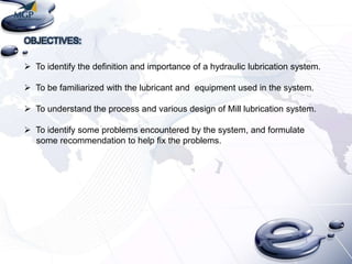


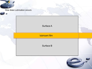
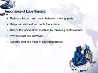
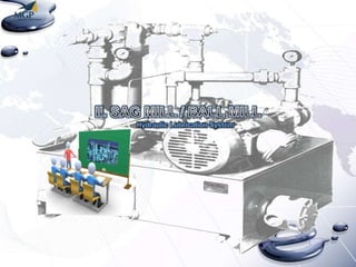
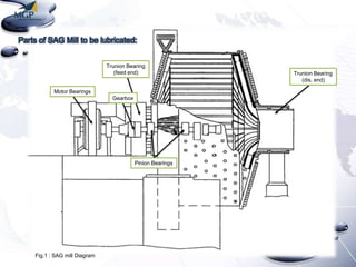
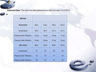
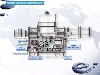
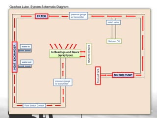
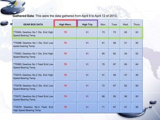
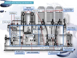
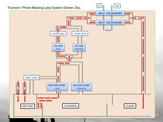
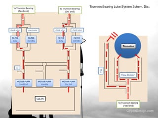
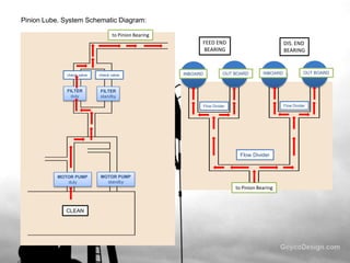
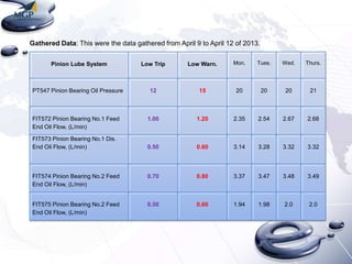
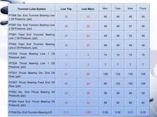
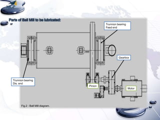

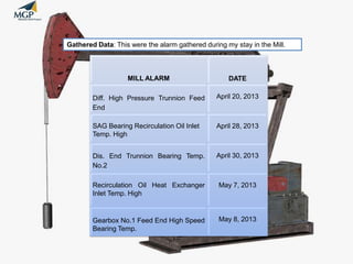

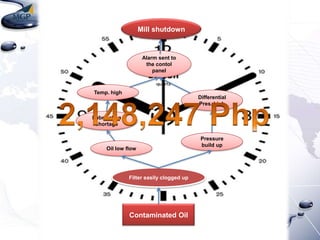
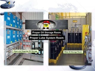

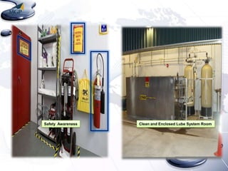
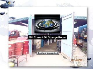
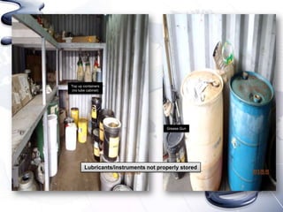
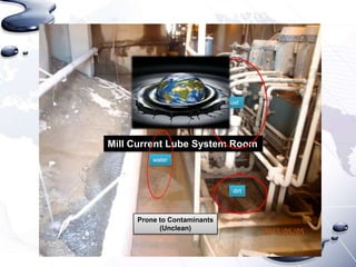
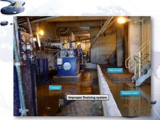
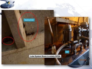
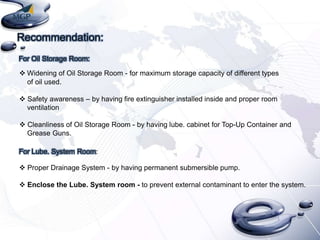


The document discusses the hydraulic lubrication system of a SAG mill. It provides definitions and discusses the importance of lubrication in reducing friction and wear between moving parts. It describes the various components of the lubrication system including the motor, gearbox, trunnion bearings and pinion bearings. It also summarizes data collected from the lubrication system from April 9-12, 2013 including temperatures, pressures, and oil flows. The document concludes with recommendations to improve the oil storage room and lubrication system room such as widening the areas, improving cleanliness, drainage, and enclosing rooms.