SlideShare a Scribd company logo
ISA
                                                                                                            TRANSACTIONS®
                                              ISA Transactions 43 ͑2004͒ 297–304


    Tuning PI controllers for stable processes with specifications
                    on gain and phase margins
                                                     Ibrahim Kaya*
                Inonu University, Engineering Fac., Dept. of Electrical & Electronics Eng., 44069 Malatya, Turkey
                                     ͑Received 28 February 2003; accepted 17 August 2003͒


Abstract
   In industrial practice, controller designs are performed based on an approximate model of the actual process. It is
essential to design a control system which will exhibit a robust performance because the physical systems can vary with
operating conditions and time. Gain and phase margins are well known parameters for evaluating the robustness of a
control system. This paper presents a tuning algorithm to design and tune PI controllers for stable processes with a
small dead time while meeting specified gain and phase margins. Simulation examples are given to demonstrate that the
proposed design method can result, in a closed-loop system, in better performances than existing design methods which
are also based on user-specified gain and phase margins. © 2004 ISA—The Instrumentation, Systems, and Automa-
tion Society.

Keywords: IMC design; PI controller; Gain margin; Phase margin; Time delay


1. Introduction                                                     ally, vary with operating conditions and time.
                                                                    Hence robustness of a control system has always
  Proportional-integral-derivative ͑PID͒ control-                   been an important issue. Gain and phase margins
lers are widely used in industrial systems despite                  are two well-known measures for maintaining the
the significant developments of recent years in                      robustness of the control system. Recently, there
control theory and technology. This is because                      has been a renewed interest in designing a control
they perform well for a wide class of processes.                    system to satisfy the specified gain and phase mar-
PID controllers give robust performance over a                      gins ͓1– 4͔.
wide range of operating conditions. Furthermore,                      This paper presents a controller design, with
they are easy to implement using analog or digital                  specifications on gain and phase margins, for con-
hardware and familiar to engineers.                                 trolling stable processes with small time delays.
  In the practice, the model used to analyze or                     To accomplish this, the classical single input
design control systems is only an approximation                     single output ͑SISO͒ feedback control system is
of the actual plant transfer function. The most                     represented as its equivalent internal model con-
common models used for stable plant transfer                        trol ͑IMC͒ ͓5,6͔. This representation provides the
functions are a first-order plus dead time ͑FOPDT͒                   parameters of PID-type controllers used in the
or second-order plus dead time ͑SOPDT͒ model.                       SISO system to be defined in terms of the desired
Also, the parameters of the physical systems, usu-                  closed-loop time constant, which can be adjusted
                                                                    by the operator, and the parameters of the process
  *Tel: ϩ90 422 3410010, ext. 4499; fax: ϩ90 422                    model. This means that only one parameter,
3410046. E-mail address: ikaya@inonu.edu.tr                         namely the desired closed-loop time constant, is

0019-0578/2004/$ - see front matter © 2004 ISA—The Instrumentation, Systems, and Automation Society.
298                              Ibrahim Kaya / ISA Transactions 43 (2004) 297–304


left for tuning, assuming that the model param-
eters have been obtained from a relay autotuning
͓7,8͔. The details of the identification method are
not given here and interested readers can refer to
the cited references. However, for the sake of easi-
ness, equations used for parameter estimation of
the FOPDT plant transfer function are given in the
Appendix. The value of the closed-loop time con-
stant is obtained from the specified gain and phase
margins. The proposed design method is compared                            Fig. 1. IMC control strategy.
with existing design methods based on the speci-
fied gain and phase margins and it is shown by                  This control structure is referred to as internal
examples that the proposed design method gives                                                             ˆ
                                                            model control ͑IMC͒ since the plant model G ( s )
better closed-loop performance.                             appears in the control structure. Here, G ( s ) and
   The next section gives a brief review of the IMC          ˆ
                                                            G ( s ) are the actual process and process model
design, since the tuning rules to tune/design PI            transfer functions, respectively. When G ( s )
controllers are derived using IMC principles.                  ˆ
                                                            ϭG ( s ) , that is perfect modeling, and dϭ0, the
Simple tuning rules for obtaining parameters of a           system is basically open loop. This provides the
PI controller based on the user-specified gain and                                                    ˆ
                                                            open-loop advantages. When G ( s ) G ( s ) or d
phase margins are derived in Section 3. Section 4
                                                               0 the system is a closed-loop system. Thus the
gives simulation examples which show that the
                                                            IMC control strategy has the advantages of both
design method given in the paper results in a bet-
                                                            the open-loop and closed-loop structures.
ter closed-loop system performance than existing
                                                               The first step in the IMC controller design is to
design methods which is designed with specifica-
                                                            factor the process model,
tions on gain and phase margins as well. Conclu-
sions are given in Section 5.                                                ˆ        ˆ         ˆ
                                                                             G ͑ s ͒ ϭG ϩ ͑ s ͒ G Ϫ ͑ s ͒ ,                   ͑1͒
                                                                    ˆ
                                                            where G ϩ ( s ) contains all the time delays and
                                                            right-half plane zeros.
2. Internal model control „IMC…                                The second step is to define the IMC controller
                                                            as
   A control system design is expected to provide a
fast and accurate set-point tracking, that is, the                         G imc ͑ s ͒ ϭG Ϫ1 ͑ s ͒ F ͑ s ͒ ,
                                                                                        ˆ
                                                                                          Ϫ                                   ͑2͒
output of the system should follow the input signal
                                                            where F ( s ) is a low pass filter with a steady-state
as close as possible. In addition, any external dis-
                                                            gain of 1. The filter is introduced for physical re-
turbances must be corrected by the control system
                                                            alizability of the IMC controller G imc ( s ) . The
as efficiently as possible. The first requirement is
                                                            simplest filter has the following form ͓5,6͔:
achieved by an open-loop control system. With an
open-loop control scheme, the stability of the sys-                                             1
tem is guaranteed provided that both the plant and                               F͑ s ͒ϭ                .                     ͑3͒
controller transfer functions are stable. Also, the                                        ͑ ␭sϩ1 ͒ n
design of the controller in an open-loop control            From the block diagram of the IMC structure
scheme may simply be chosen as G c ( s )                    shown in Fig. 1, the closed-loop transfer is given
ϭG Ϫ1 ( s ) , where G c ( s ) and G ( s ) are, respec-      by
tively, the controller and plant transfer functions.
The drawback of an open-loop control system is                                          G ͑ s ͒ G imc ͑ s ͒
                                                                    T r͑ s ͒ ϭ                  ˆ                         .   ͑4͒
the sensitivity to modeling errors and inability to                              1ϩ ͓ G ͑ s ͒ ϪG ͑ s ͔͒ G     imc ͑ s ͒
deal with external disturbances entering the sys-
tem. In this case, a closed-loop system can be used         The disturbance transfer function of the IMC
to deal with disturbances and modeling errors.              structure is
Rivera et al. ͓5͔ proposed the control structure                                            ˆ
                                                                                      1ϪG ͑ s ͒ G imc ͑ s ͒
given in Fig. 1.                                                    T d͑ s ͒ ϭ                 ˆ                    .         ͑5͒
                                                                                 1ϩ ͓ G ͑ s ͒ ϪG ͑ s ͔͒ G imc ͑ s ͒
Ibrahim Kaya / ISA Transactions 43 (2004) 297–304                                299


Substituting Eq. ͑2͒ into Eqs. ͑4͒ and ͑5͒ gives
                              G͑ s ͒F͑ s ͒
       T r͑ s ͒ ϭ ˆ                      ˆ                    ͑6͒
                  G Ϫ ͑ s ͒ ϩ ͓ G ͑ s ͒ ϪG ͑ s ͔͒ F ͑ s ͒
and
                         ˆ
                        G Ϫ ͑ s ͓͒ 1ϪF ͑ s ͔͒
      T d͑ s ͒ ϭ ˆ                      ˆ                .    ͑7͒
                 G Ϫ ͑ s ͒ ϩ ͓ G ͑ s ͒ ϪG ͑ s ͔͒ F ͑ s ͒              Fig. 2. IMC representation of a SISO control system.

                               ˆ
For perfect modeling, G ( s ) ϭG ( s ) , and nonmini-
mum phase systems, G Ϫˆ ( s ) ϭG ( s ) , Eqs. ͑6͒ and
                                ˆ                                      To find the tuning parameters for the controller
͑7͒ can be further simplified to give                                G c ( s ) in Fig. 2, stable first-order plus dead time
                                                                    ͑FOPDT͒ plant transfer function is considered. It
                       T r ͑ s ͒ ϭF ͑ s ͒                     ͑8͒   should be pointed out that the FOPDT model is
                                                                    only used for simplifying calculations and that the
and
                                                                    actual process may be a higher-order process or a
                    T d ͑ s ͒ ϭ1ϪF ͑ s ͒ .                    ͑9͒   process with complex poles, etc. In order to obtain
                                                                    the IMC controller, the process FOPDT model,
Eqs. ͑8͒ and ͑9͒ show that the performance of a
                                                                    G ( s ) ϭKe Ϫ ␪ s / ( Tsϩ1 ) , must be factored as in
                                                                     ˆ
closed-loop system designed based on the IMC
                                                                    Eq. ͑1͒:
design method is determined solely by the filter
dynamics. For a filter with the form given by Eq.                                       G ϩ ͑ s ͒ ϭe Ϫ ␪ s ,
                                                                                       ˆ                               ͑14͒
͑3͒ and for t→ϱ, Eqs. ͑8͒ and ͑9͒ give c r ( t ) →1
and c d ( t ) →0.                                                                     ˆ               K
                                                                                      G Ϫ͑ s ͒ ϭ         .             ͑15͒
                                                                                                    Tsϩ1
3. Controller design
                                                                    The IMC controller can be obtained from Eq. ͑2͒,
  The closed-loop transfer function of a classical                  assuming a filter with nϭ1, as
SISO feedback system and IMC design, for per-
fect matching, are, respectively, given by                                                           Tsϩ1
                                                                                   G imc ͑ s ͒ ϭ              .        ͑16͒
                                                                                                   K ͑ ␭sϩ1 ͒
                              G c͑ s ͒ G ͑ s ͒
              T siso ͑ s ͒ ϭ                                 ͑10͒   Using a first-order Taylor series expansion for the
                             1ϩG c ͑ s ͒ G ͑ s ͒
                                                                    time-delay approximation, the classic controller
and                                                                 G c ( s ) can be obtained from Eq. ͑13͒,
               T imc ͑ s ͒ ϭG imc ͑ s ͒ G ͑ s ͒ .            ͑11͒                                  Tsϩ1
                                                                                    G c͑ s ͒ ϭ                .        ͑17͒
In order to have the same output for both configu-                                                K ͑ ␭ϩ ␪ ͒ s
rations, it is easy to illustrate, by comparing Eqs.
                                                                    Eq. ͑17͒ is rearranged as an ideal PI controller,
͑10͒ and ͑11͒, that the IMC controller G imc ( s ) is
                                                                    which has the following controller parameters:
related to the classic controller G c ( s ) through the
transformation                                                                                     T
                                                                                       K pϭ              ,             ͑18͒
                              G c͑ s ͒                                                        K ͑ ␭ϩ ␪ ͒
              G imc ͑ s ͒ ϭ                                  ͑12͒
                            1ϩG c ͑ s ͒ G ͑ s ͒                                             T i ϭT.                    ͑19͒
or                                                                  The only unknown in the last two equations is the
                          G imc ͑ s ͒                               filter time constant ␭, since it is assumed that the
             G c͑ s ͒ ϭ                       .              ͑13͒   plant transfer function model is obtained from the
                        1ϪG imc ͑ s ͒ G ͑ s ͒
                                                                    exact relay feedback identification method given
Therefore from Eq. ͑12͒ a classical SISO feedback                   in Refs. ͓7,8͔. Thus if a proper value of ␭ is
system can be put into the IMC structure as shown                   achieved, then the design procedure will be com-
in Fig. 2.                                                          pleted. Here, the value of ␭ is obtained from gain
300                                     Ibrahim Kaya / ISA Transactions 43 (2004) 297–304


and phase margin specifications, which are well-
known robustness parameters.
  The characteristic equation of a SISO control
system is given by 1ϩG c ( s ) G ( s ) . Hence the
open-loop transfer function of the SISO control
system, with G c ( s ) given by Eq. ͑17͒, is
                                    e Ϫ␪s
              G c͑ s ͒ G ͑ s ͒ ϭ            .           ͑20͒
                                 ͑ ␭ϩ ␪ ͒ s                        Fig. 3. The block diagram for computing the controller,
                                                                   G c (s), parameters.
Therefore from the basic definitions of the gain
and phase margins the following equations can be                   The recommended ranges for the gain and phase
obtained:                                                          margins are between 2 and 5 and 30° and 60°,
           arg͕ G c ͑ j ␻ p ͒ G ͑ j ␻ p ͒ ͖ ϭϪ ␲ ,      ͑21͒       respectively ͓9͔. Choosing A m ϭ3, then ␾ m
                                                                   ϭ60°. Therefore the closed-loop time constant ␭
             A m ͉ G c ͑ j ␻ p ͒ G ͑ j ␻ p ͒ ͉ ϭ1,      ͑22͒       is obtained, by rearranging Eqs. ͑25͒ and ͑26͒, as

               ͉ G c ͑ j ␻ g ͒ G ͑ j ␻ g ͒ ͉ ϭ1,        ͑23͒                     ␭ϭ ␪   ͩ   2A m
                                                                                             ␲     ͪ
                                                                                                 Ϫ1 ϭ0.91␪ .         ͑31͒
         ␾ m ϭ ␲ ϩarg͕ G c ͑ j ␻ p ͒ G ͑ j ␻ p ͒ ͖ ,    ͑24͒
                                                                   Hence the PI controller parameters are given by
where the gain margin is given by Eqs. ͑21͒ and                    Eqs. ͑18͒ and ͑19͒ with ␭ given by Eq. ͑31͒.
͑22͒, and the phase margin by Eqs. ͑23͒ and ͑24͒.                    Remark: If a second-order plus dead time
The frequency ␻ p is known as phase crossover                      ͑SOPDT͒ plant transfer function model, G ( s )ˆ
                                                                           Ϫ␪s
frequency, where the Nyquist curve has a phase                     ϭKe / ( T 1 sϩ1 )( T 2 sϩ1 ) , instead of the
lag of Ϫ␲, and the frequency ␻ g is known as the                   FOPDT model, is assumed, then the controller
gain crossover frequency, where the Nyquist curve                  G c ( s ) will be a PID controller. However, it has
has an amplitude of 1.                                             been observed during extensive simulations that
  Substituting Eq. ͑20͒ into Eqs. ͑21͒–͑24͒, results               using a PID controller provides a little improve-
in the following set of equations:                                 ment in the closed-loop performance of the sys-
                                                                   tem. Hence simulation results only for the PI con-
                                  ␲
                        ␻ p␪ ϭ      ,                   ͑25͒       troller are given.
                                  2
                                                                   3.1. Tuning procedure
                   A m ϭ ␻ p ͑ ␭ϩ ␪ ͒ ,                 ͑26͒

                             1                                        The block diagram for obtaining the PI control-
                       ␻ gϭ      ,                      ͑27͒       ler, G c ( s ) , parameters, based on the specified gain
                            ␭ϩ ␪                                   and phase margins, is shown in Fig. 3. The tuning
                                                                   procedure can be carried out as follows:
                        ␲
                    ␾ mϭ Ϫ ␻ g␪ .                       ͑28͒          1. When the controller needs to be tuned,
                        2                                          switch from the controller mode to relay mode.
                                                                      2. Measure the limit cycle parameters and esti-
From Eqs. ͑26͒ and ͑27͒ one can obtain
                                                                   mate the parameters of the FOPDT plant transfer
                      A m␻ gϭ ␻ p .                     ͑29͒       function using the relay feedback method. Equa-
                                                                   tions to compute the parameters of the FOPDT
Multiplying both sides of Eq. ͑29͒ with ␪ and then                 plant transfer function are provided in the Appen-
substituting values of ␻ g ␪ and ␻ p ␪ from Eqs. ͑25͒              dix.
and ͑28͒, the relation between gain and phase mar-                    3. Find the PI controller parameters using Eqs.
gin can be obtained as                                             ͑18͒ and ͑19͒, in conjunction with Eq. ͑31͒.

                             ͩ            ͪ
                                                                      4. Switch from the relay mode to the controller
                          ␲    1                                   mode with calculated tuning parameters for the
                  ␾ mϭ      1Ϫ    .                     ͑30͒
                          2    Am                                  control of the process.
Ibrahim Kaya / ISA Transactions 43 (2004) 297–304                             301


                                                                       Fig. 5. Control signals for example 1.
         Fig. 4. Step responses for example 1.

                                                             that with the proposed design method less effort is
4. Simulation examples                                       required for the control action, for both design
                                                             methods.
   Several examples are presented to illustrate the            Example 2: In this example, a real industrial
use of the proposed method. Since the presented              HVAC system used in Wang et al. ͓3͔ with trans-
design method is model based, the identification              fer function of G ( s ) ϭe Ϫ2s / ( 0.12s 2 ϩ1.33s
method given by Kaya ͓7͔ or Kaya and Atherton                ϩ1.24) is considered. The FOPDT model was ob-
͓8͔ has been used to find the FOPDT model. The                tained as G ( s ) ϭ0.81e Ϫ2.78s / ( 1.011sϩ1 ) , using
identification method has been used for all transfer          the estimation method given in Refs. ͓7,8͔. The PI
functions in the examples but since it gives essen-          controller parameters are K p ϭ0.235 and T i
tially exact results on simulation data the esti-            ϭ1.011, when Eqs. ͑18͒ and ͑19͒ are used in con-
mated plant transfer functions are only given for            junction with Eq. ͑31͒. The PID controller param-
original plants of higher order. In all the examples,        eters used by Wang et al. ͓3͔ are K p ϭ0.611, T i
controllers, for both the proposed design method             ϭ1.441, and T d ϭ0.564. The response of the
and design methods that are used for comparison,             closed-loop system with designed controllers for
are designed for a gain and phase margin of 3 and            both design methods to a unity step set-point
60°, respectively.                                           change together with load disturbance introduced
   Example 1: Consider a second-order plus dead              at time 30 s are given in Fig. 6. The assumed load
time plant transfer function of G ( s ) ϭe Ϫ1.0s / ( s       disturbance magnitude was Ϫ0.5. In terms of
ϩ1 )( 0.5sϩ1 ) , which was given in Ref. ͓1͔. The
identification method given in Refs. ͓7,8͔ was
used to obtain the FOPDT model as G ( s )
ϭe Ϫ1.34s / ( 1.44sϩ1 ) . Therefore the PI controller
parameters are obtained from Eqs. ͑18͒ and ͑19͒,
in conjunction with Eq. ͑31͒, to be K p ϭ0.563 and
T i ϭ1.44. The controller parameters for the design
method proposed by Ho et al. ͓1͔ are K p ϭ0.52,
T i ϭ1.00, and T d ϭ0.50. The closed-loop re-
sponses for both design methods are given in Fig.
4 for a unity step set-point change and a distur-
bance with magnitude of Ϫ0.5 introduced at time
30 s. As is seen from the figure, the proposed de-
sign method results in a better performance for
both the set-point response and disturbance rejec-
tion. Fig. 5 illustrates control signals, which show                   Fig. 6. Step responses for example 2.
302                                Ibrahim Kaya / ISA Transactions 43 (2004) 297–304


                                                                        Fig. 8. Step responses for example 3.
         Fig. 7. Control signals for example 2.

                                                              illustrates that with the proposed method less ef-
                                                              fort is necessary for the control action.
maximum overshoot, the proposed design method                    Example 4: A high-order oscillating plant trans-
gives better performance than the design method               fer function of G ( s ) ϭe Ϫs / ( s 2 ϩsϩ1 )( sϩ3 ) ,
proposed by Wang et al. ͓3͔ for the set-point re-             which was used by Wang and Shao ͓4͔, is consid-
sponse. In terms of settling time, both design                ered. Again, the parameter estimation method
methods give similar responses. The load distur-              given in Refs. ͓7,8͔ was employed to generate the
bance rejection of the design method suggested by             FOPDT model as G ( s ) ϭ0.333e Ϫ3.1s / ( 0.075s
Wang et al. ͓3͔ is slightly faster than the proposed          ϩ1 ) . Once a proper model is found, the PI con-
one. This is expected, since in the proposed design           troller tuning parameters were calculated to be
method pole zero cancellations are used and this in           K p ϭ0.038 and T i ϭ0.075. Wang and Shao sug-
some cases may lead to a sluggish load distur-                gested a PID controller with settings of K p
bance rejection. However, when comparing the                  ϭ1.298, T i ϭ1.034, and T d ϭ1.017. With these
control signals, shown in Fig. 7, it is seen that the         calculated controller settings, the step response of
proposed design method requires less attempt for              the closed-loop system to a unity step set-point
the control action.                                           change and a disturbance of magnitude of Ϫ0.5
  Example 3: A high-order plant transfer function             introduced at time 50 s is shown in Fig. 10. Again,
of G ( s ) ϭ1/( sϩ1 ) 8 , which was given in Wang             the proposed design method results in a better per-
and Shao ͓4͔, is considered in this example. The              formance, especially for set point response. In Fig.
identification method given in Refs. ͓7,8͔ was                 11, control signals for both design methods are
used to find the FOPDT model, G ( s )
ϭe Ϫ5.10s / ( 4.35sϩ1 ) . Using Eqs. ͑18͒ and ͑19͒
together with Eq. ͑31͒, the PI controller settings
were found to be K p ϭ0.447 and T i ϭ4.340. The
PID controller parameters suggested by Wang and
Shao ͓4͔ are K p ϭ0.677, T i ϭ4.340, and T d
ϭ1.649. Fig. 8 illustrates responses for both de-
sign methods to a unity set-point change together
with load disturbance introduced at time 80 s. The
load disturbance magnitude was again assumed to
be Ϫ0.5. The proposed design method, as is seen
from Fig. 8, results in a better closed-loop system
performance in terms of maximum overshoot,
while in terms of the settling time both designs
give quite similar performances. Control signals
for this example are given in Fig. 9, which again                       Fig. 9. Control signals for example 3.
Ibrahim Kaya / ISA Transactions 43 (2004) 297–304                                               303


                                                             controller may lead to sluggish load disturbance
                                                             rejection, again due to pole zero cancellation used
                                                             in the design procedure. However, in the examples
                                                             given in this paper, it is seen that the load distur-
                                                             bance rejection of the proposed design method is
                                                             also satisfactory.

                                                             Appendix: Model identification

                                                                In this section, equations used to identify the
                                                             unknown parameters of the FOPDT plant transfer
                                                             function are given. The identification method
        Fig. 10. Step responses for example 4.               makes use of the relay autotuning. The given
                                                             equations will result in exact parameter estima-
                                                             tions, assuming no measurement errors. The de-
given. Again, it is seen that the process can be             tails can be found in Refs. ͓7,8͔.
controlled with less effort by the proposed design              Two equations for the limit cycle frequency ␻
method.                                                      and the pulse duration ⌬t 1 can be obtained and are
                                                             given by


                                                                 ͩ                                            ͪ
5. Conclusions
                                                                      Ϫ ␻ ⌬t 1 ␲ ͑ e ⌬t 1 /T Ϫ1 ͒ e ␪ /T
  Simple tuning rules for a PI controller for con-           K                ϩ
                                                                         2         ͑ e 2 ␲ /␭ Ϫ1 ͒
trolling stable process with small time delays have
been derived using specified gain and phase mar-
gin specifications. The design method presented in
this paper is model based. Therefore first a
                                                                      ϭ   ͩ       ␲
                                                                              h 1 Ϫh 2   ͪͩ   RϪ⌬Ϫ
                                                                                                     G ͑ 0 ͓͒ h 1 ⌬t 1 ϩh 2 ⌬t 2 ͔
                                                                                                                   P                 ͪ
FOPDT plant transfer function model was ob-                                                                                      ͑A1͒
tained from a single relay feedback test with exact          and


                                                                  ͩ                                                         ͪ
limit cycle analysis. Once the model was found,
simple tuning rules provided in the paper were                        ␻ ⌬t 1 Ϫ2 ␲ ␲ ͑ e ͑ Ϫ ␻ ⌬t 1 ϩ2 ␲ ͒ /␭ Ϫ1 ͒ e ␪ /T
used to control the process. Since the proposed               K                  ϩ
design method incorporates IMC design prin-
                                                                           2                 ͑ e 2 ␲ /␭ Ϫ1 ͒

                                                                         ͩ               ͪͩ                                       ͪ
ciples, where pole zero cancellation is used, the                              Ϫ␲                    G ͑ 0 ͓͒ h 1 ⌬t 1 ϩh 2 ⌬t 2 ͔
closed-loop system with designed PI controller re-                   ϭ                        Rϩ⌬Ϫ                                 ,
sults in good set point responses. The designed                              h 1 Ϫh 2                              P
                                                                                                                                 ͑A2͒
                                                             where h 1 and h 2 are the relay heights and ⌬ is the
                                                             hysteresis. ⌬t 1 and ⌬t 2 are the pulse durations
                                                             and Pϭ⌬t 1 ϩ⌬t 2 is the period of the oscillation.
                                                             R is a constant valued signal entering the system
                                                             and ␭ϭ ␻ T.
                                                               Two more equations can be obtained for the
                                                             maximum and minimum of the plant output wave
                                                             form which are given by the following equations:

                                                                       a minϭ
                                                                                 G ͑ 0 ͓͒ h 1 ⌬t 1 ϩh 2 ⌬t 2 ͔
                                                                                               P
                                                                                                               ϩ  ͩ
                                                                                                                 h 1 Ϫh 2
                                                                                                                     ␲       ͪ
        Fig. 11. Control signals for example 4.
                                                                                 ϫ   ͩ   Ϫ ␻ ⌬t 1 ␲ ͑ e ⌬t 1 /T Ϫ1 ͒
                                                                                            2
                                                                                                 ϩ
                                                                                                   ͑ e 2 ␲ /␭ Ϫ1 ͒
                                                                                                                       ͪ        ͑A3͒
304                                       Ibrahim Kaya / ISA Transactions 43 (2004) 297–304


and                                                                  either Eq. ͑A3͒ if a min is measured or Eq. ͑A4͒ if

                                              ͩ           ͪ
                                                                     a max is measured. Finally, with K and T known,
               G ͑ 0 ͓͒ h 1 ⌬t 1 ϩh 2 ⌬t 2 ͔   h 1 Ϫh 2
      a maxϭ                                 ϩ                       the dead time ␪ can be calculated from either Eq.
                             P                     ␲                 ͑A1͒ or Eq. ͑A2͒.

               ϫ   ͩ   Ϫ ␻ ⌬t 1 ␲ e 2 ␲ /␭ ͑ 1Ϫe Ϫ⌬t 1 /T ͒
                          2
                               ϩ
                                      ͑ e 2 ␲ /␭ Ϫ1 ͒
                                                            . ͪ      References
                                                                      ͓1͔ Ho, W. K., Hang, C. C., and Cao, L., Tuning of PID
                                                                          controllers based on gain and phase margin specifica-
                                                              ͑A4͒        tions. Automatica 31, 497–502 ͑1995͒.
                                                                      ͓2͔ Fung, H. W., Wang, Q. G., and Lee, T. H., PI Tuning
Although Eqs. ͑A1͒–͑A4͒ obtained for a stable                             in terms of gain and phase margins. Automatica 34,
FOPDT transfer function are sufficient to identify                         1145–1149 ͑1998͒.
                                                                      ͓3͔ Wang, Q. G., Fung, H. W., and Zhang, Y., PID tuning
the unknown parameters, K, T, and ␪, initial                              with exact gain and phase margins. ISA Trans. 38,
guesses are required for the unknowns to solve                            243–249 ͑1999͒.
these nonlinear equations. To reduce the number                       ͓4͔ Wang, Y. G. and Shao, H. H., PID autotuner based on
of unknowns and make the solution easier to find,                          gain- and phase-margin specifications. Ind. Eng.
                                                                          Chem. Res. 38, 3007–3012 ͑1999͒.
Fourier analysis can be used to identify the steady-                  ͓5͔ Rivera, D. E., Morari, M., and Sigurd, S., Internal
state gain K from                                                         model control. 4. PID controller design. Ind. Eng.
                                                                          Chem. Process Des. Dev. 25, 252–265 ͑1986͒.
                               ͵ c͑ t ͒dt
                                     0
                                      P
                                                                      ͓6͔ Morari, M. and Zafiriou, E., Robust Process Control.
                                                                          Prentice-Hall, Englewood Cliffs, NJ, 1989.
                   KϭG ͑ 0 ͒ ϭ                                ͑A5͒    ͓7͔ Kaya, I., Relay feedback identification and model
                               ͵ y ͑ t ͒dt
                                      P
                                           ,
                                                                          based controller design. Ph.D. thesis, University of
                                     0                                    Sussex, U.K., 1999.
                                                                      ͓8͔ Kaya, I. and Atherton, D. P., Parameter estimation
where c ( t ) is the plant output, y ( t ) is the relay                   from relay autotuning with asymmetric limit cycle
                                                                          data. J. Process Control 11, 429– 439 ͑2001͒.
output, and P is the period.                                               ˚ ¨
                                                                      ͓9͔ Astrom, K. J. and Hagglund, T., PID Controllers:
                                                                                                 ¨
  Once the steady-state gain K is obtained from                           Theory, Design and Tuning. Instrument Society of
Eq. ͑A5͒, the time constant T can be obtained from                        America, Research Triangle Park, NC, 1995.

More Related Content

What's hot

Controller Tuning for Integrator Plus Delay Processes.
Controller Tuning for Integrator Plus Delay Processes.Controller Tuning for Integrator Plus Delay Processes.
Controller Tuning for Integrator Plus Delay Processes.
theijes
 
Design PID controllers for desired time domain or frequency domain response
Design PID controllers for desired time domain or frequency domain responseDesign PID controllers for desired time domain or frequency domain response
Design PID controllers for desired time domain or frequency domain responseISA Interchange
 
Robust PID controller design for non-minimum phase time delay systems
Robust PID controller design for non-minimum phase time delay systemsRobust PID controller design for non-minimum phase time delay systems
Robust PID controller design for non-minimum phase time delay systemsISA Interchange
 
Future Perspectives of PID Control
Future Perspectives of PID ControlFuture Perspectives of PID Control
Future Perspectives of PID Control
Emerson Exchange
 
Intelligent PID Product Design
Intelligent PID Product DesignIntelligent PID Product Design
Intelligent PID Product Design
Emerson Exchange
 
Fuzzy controlled mine drainage system based on embedded system
Fuzzy controlled mine drainage system based on embedded systemFuzzy controlled mine drainage system based on embedded system
Fuzzy controlled mine drainage system based on embedded system
IRJET Journal
 
Fuzzy logic control vs. conventional pid
Fuzzy logic control vs. conventional pidFuzzy logic control vs. conventional pid
Fuzzy logic control vs. conventional pid
Mauricio Sanchez Portilla
 
70
7070
Model Predictive Control For Integrating Processes
Model Predictive Control For Integrating ProcessesModel Predictive Control For Integrating Processes
Model Predictive Control For Integrating Processes
Emerson Exchange
 
Smooooth Operations - Configuration Tips for Analog Blocks
Smooooth Operations - Configuration Tips for Analog BlocksSmooooth Operations - Configuration Tips for Analog Blocks
Smooooth Operations - Configuration Tips for Analog Blocks
Emerson Exchange
 
Study of PID Controllers to Load Frequency Control Systems with Various Turbi...
Study of PID Controllers to Load Frequency Control Systems with Various Turbi...Study of PID Controllers to Load Frequency Control Systems with Various Turbi...
Study of PID Controllers to Load Frequency Control Systems with Various Turbi...
IJERA Editor
 
Adaptive Functional-Based Neuro-Fuzzy-PID Incremental Controller Structure
Adaptive Functional-Based Neuro-Fuzzy-PID Incremental Controller StructureAdaptive Functional-Based Neuro-Fuzzy-PID Incremental Controller Structure
Adaptive Functional-Based Neuro-Fuzzy-PID Incremental Controller Structure
ijeei-iaes
 
M ODEL P REDICTIVE C ONTROL U SING F PGA
M ODEL  P REDICTIVE  C ONTROL  U SING  F PGAM ODEL  P REDICTIVE  C ONTROL  U SING  F PGA
M ODEL P REDICTIVE C ONTROL U SING F PGA
ijctcm
 
Speed Control of DC Motor using PID FUZZY Controller.
Speed Control of DC Motor using PID FUZZY Controller.Speed Control of DC Motor using PID FUZZY Controller.
Speed Control of DC Motor using PID FUZZY Controller.
Binod kafle
 
Low-cost quadrotor hardware design with PID control system as flight controller
Low-cost quadrotor hardware design with PID control system as flight controllerLow-cost quadrotor hardware design with PID control system as flight controller
Low-cost quadrotor hardware design with PID control system as flight controller
TELKOMNIKA JOURNAL
 
IRJET- An Improved DCM-Based Tunable True Random Number Generator for Xilinx ...
IRJET- An Improved DCM-Based Tunable True Random Number Generator for Xilinx ...IRJET- An Improved DCM-Based Tunable True Random Number Generator for Xilinx ...
IRJET- An Improved DCM-Based Tunable True Random Number Generator for Xilinx ...
IRJET Journal
 
IRJET- Hybrid Intelligent Controller for Interior Permanent Magnet Synchr...
IRJET-  	  Hybrid Intelligent Controller for Interior Permanent Magnet Synchr...IRJET-  	  Hybrid Intelligent Controller for Interior Permanent Magnet Synchr...
IRJET- Hybrid Intelligent Controller for Interior Permanent Magnet Synchr...
IRJET Journal
 
Driving Forces and Key Benefits of Control System Migrations
Driving Forces and Key Benefits of Control System MigrationsDriving Forces and Key Benefits of Control System Migrations
Driving Forces and Key Benefits of Control System Migrations
Optima Control Solutions
 
C0325010015
C0325010015C0325010015
C0325010015
theijes
 

What's hot (20)

Controller Tuning for Integrator Plus Delay Processes.
Controller Tuning for Integrator Plus Delay Processes.Controller Tuning for Integrator Plus Delay Processes.
Controller Tuning for Integrator Plus Delay Processes.
 
Design PID controllers for desired time domain or frequency domain response
Design PID controllers for desired time domain or frequency domain responseDesign PID controllers for desired time domain or frequency domain response
Design PID controllers for desired time domain or frequency domain response
 
Robust PID controller design for non-minimum phase time delay systems
Robust PID controller design for non-minimum phase time delay systemsRobust PID controller design for non-minimum phase time delay systems
Robust PID controller design for non-minimum phase time delay systems
 
Future Perspectives of PID Control
Future Perspectives of PID ControlFuture Perspectives of PID Control
Future Perspectives of PID Control
 
Intelligent PID Product Design
Intelligent PID Product DesignIntelligent PID Product Design
Intelligent PID Product Design
 
Fuzzy controlled mine drainage system based on embedded system
Fuzzy controlled mine drainage system based on embedded systemFuzzy controlled mine drainage system based on embedded system
Fuzzy controlled mine drainage system based on embedded system
 
Fuzzy logic control vs. conventional pid
Fuzzy logic control vs. conventional pidFuzzy logic control vs. conventional pid
Fuzzy logic control vs. conventional pid
 
70
7070
70
 
Model Predictive Control For Integrating Processes
Model Predictive Control For Integrating ProcessesModel Predictive Control For Integrating Processes
Model Predictive Control For Integrating Processes
 
Smooooth Operations - Configuration Tips for Analog Blocks
Smooooth Operations - Configuration Tips for Analog BlocksSmooooth Operations - Configuration Tips for Analog Blocks
Smooooth Operations - Configuration Tips for Analog Blocks
 
Study of PID Controllers to Load Frequency Control Systems with Various Turbi...
Study of PID Controllers to Load Frequency Control Systems with Various Turbi...Study of PID Controllers to Load Frequency Control Systems with Various Turbi...
Study of PID Controllers to Load Frequency Control Systems with Various Turbi...
 
Adaptive Functional-Based Neuro-Fuzzy-PID Incremental Controller Structure
Adaptive Functional-Based Neuro-Fuzzy-PID Incremental Controller StructureAdaptive Functional-Based Neuro-Fuzzy-PID Incremental Controller Structure
Adaptive Functional-Based Neuro-Fuzzy-PID Incremental Controller Structure
 
M ODEL P REDICTIVE C ONTROL U SING F PGA
M ODEL  P REDICTIVE  C ONTROL  U SING  F PGAM ODEL  P REDICTIVE  C ONTROL  U SING  F PGA
M ODEL P REDICTIVE C ONTROL U SING F PGA
 
Speed Control of DC Motor using PID FUZZY Controller.
Speed Control of DC Motor using PID FUZZY Controller.Speed Control of DC Motor using PID FUZZY Controller.
Speed Control of DC Motor using PID FUZZY Controller.
 
Low-cost quadrotor hardware design with PID control system as flight controller
Low-cost quadrotor hardware design with PID control system as flight controllerLow-cost quadrotor hardware design with PID control system as flight controller
Low-cost quadrotor hardware design with PID control system as flight controller
 
IRJET- An Improved DCM-Based Tunable True Random Number Generator for Xilinx ...
IRJET- An Improved DCM-Based Tunable True Random Number Generator for Xilinx ...IRJET- An Improved DCM-Based Tunable True Random Number Generator for Xilinx ...
IRJET- An Improved DCM-Based Tunable True Random Number Generator for Xilinx ...
 
24
2424
24
 
IRJET- Hybrid Intelligent Controller for Interior Permanent Magnet Synchr...
IRJET-  	  Hybrid Intelligent Controller for Interior Permanent Magnet Synchr...IRJET-  	  Hybrid Intelligent Controller for Interior Permanent Magnet Synchr...
IRJET- Hybrid Intelligent Controller for Interior Permanent Magnet Synchr...
 
Driving Forces and Key Benefits of Control System Migrations
Driving Forces and Key Benefits of Control System MigrationsDriving Forces and Key Benefits of Control System Migrations
Driving Forces and Key Benefits of Control System Migrations
 
C0325010015
C0325010015C0325010015
C0325010015
 

Similar to Tuning PI controllers for stable processes with specifications on gain and phase margins

Design of PI controllers for achieving time and frequency domain specificatio...
Design of PI controllers for achieving time and frequency domain specificatio...Design of PI controllers for achieving time and frequency domain specificatio...
Design of PI controllers for achieving time and frequency domain specificatio...
ISA Interchange
 
A fuzzy model based adaptive pid controller design for nonlinear and uncertai...
A fuzzy model based adaptive pid controller design for nonlinear and uncertai...A fuzzy model based adaptive pid controller design for nonlinear and uncertai...
A fuzzy model based adaptive pid controller design for nonlinear and uncertai...
ISA Interchange
 
Improving performance using cascade control and a Smith predictor
Improving performance using cascade control and a Smith predictorImproving performance using cascade control and a Smith predictor
Improving performance using cascade control and a Smith predictorISA Interchange
 
Design of multiloop controller for multivariable system using coefficient 2
Design of multiloop controller for multivariable system using coefficient 2Design of multiloop controller for multivariable system using coefficient 2
Design of multiloop controller for multivariable system using coefficient 2IAEME Publication
 
Auto tuning of cascade control systems
Auto tuning of cascade control systemsAuto tuning of cascade control systems
Auto tuning of cascade control systemsISA Interchange
 
IRJET- Analysis of 3-Phase Induction Motor with High Step-Up PWM DC-DC Conver...
IRJET- Analysis of 3-Phase Induction Motor with High Step-Up PWM DC-DC Conver...IRJET- Analysis of 3-Phase Induction Motor with High Step-Up PWM DC-DC Conver...
IRJET- Analysis of 3-Phase Induction Motor with High Step-Up PWM DC-DC Conver...
IRJET Journal
 
IRJET- Design and Analysis of Fuzzy and GA-PID Controllers for Optimized Perf...
IRJET- Design and Analysis of Fuzzy and GA-PID Controllers for Optimized Perf...IRJET- Design and Analysis of Fuzzy and GA-PID Controllers for Optimized Perf...
IRJET- Design and Analysis of Fuzzy and GA-PID Controllers for Optimized Perf...
IRJET Journal
 
Controller tuning.pptx
Controller tuning.pptxController tuning.pptx
Controller tuning.pptx
SuvenduMondal12
 
FRACTIONAL ORDER PID CONTROLLER TUNING BASED ON IMC
FRACTIONAL ORDER PID CONTROLLER TUNING BASED ON IMC FRACTIONAL ORDER PID CONTROLLER TUNING BASED ON IMC
FRACTIONAL ORDER PID CONTROLLER TUNING BASED ON IMC
IJITCA Journal
 
At4201308314
At4201308314At4201308314
At4201308314
IJERA Editor
 
Optimised control using Proportional-Integral-Derivative controller tuned usi...
Optimised control using Proportional-Integral-Derivative controller tuned usi...Optimised control using Proportional-Integral-Derivative controller tuned usi...
Optimised control using Proportional-Integral-Derivative controller tuned usi...
IJECEIAES
 
DC Motor Position Control Using Fuzzy Proportional-Derivative Controllers Wit...
DC Motor Position Control Using Fuzzy Proportional-Derivative Controllers Wit...DC Motor Position Control Using Fuzzy Proportional-Derivative Controllers Wit...
DC Motor Position Control Using Fuzzy Proportional-Derivative Controllers Wit...
IOSR Journals
 
DC Motor Position Control Using Fuzzy Proportional-Derivative Controllers Wit...
DC Motor Position Control Using Fuzzy Proportional-Derivative Controllers Wit...DC Motor Position Control Using Fuzzy Proportional-Derivative Controllers Wit...
DC Motor Position Control Using Fuzzy Proportional-Derivative Controllers Wit...
IOSR Journals
 
F010133747
F010133747F010133747
F010133747
IOSR Journals
 
International Journal of Engineering Research and Development (IJERD)
International Journal of Engineering Research and Development (IJERD)International Journal of Engineering Research and Development (IJERD)
International Journal of Engineering Research and Development (IJERD)
IJERD Editor
 
Heat Ventilation & Air- Conditioning System with Self-Tuning Fuzzy PI Controller
Heat Ventilation & Air- Conditioning System with Self-Tuning Fuzzy PI ControllerHeat Ventilation & Air- Conditioning System with Self-Tuning Fuzzy PI Controller
Heat Ventilation & Air- Conditioning System with Self-Tuning Fuzzy PI Controller
IJMER
 
Optimal tuning of pid power system stabilizer in simulink environment
Optimal tuning of pid power system stabilizer in simulink environmentOptimal tuning of pid power system stabilizer in simulink environment
Optimal tuning of pid power system stabilizer in simulink environmentIAEME Publication
 
Design of imc based controller for industrial purpose
Design of imc based controller for industrial purposeDesign of imc based controller for industrial purpose
Design of imc based controller for industrial purpose
375ankit
 
Design of a new PID controller using predictive functional control optimizati...
Design of a new PID controller using predictive functional control optimizati...Design of a new PID controller using predictive functional control optimizati...
Design of a new PID controller using predictive functional control optimizati...
ISA Interchange
 

Similar to Tuning PI controllers for stable processes with specifications on gain and phase margins (20)

Design of PI controllers for achieving time and frequency domain specificatio...
Design of PI controllers for achieving time and frequency domain specificatio...Design of PI controllers for achieving time and frequency domain specificatio...
Design of PI controllers for achieving time and frequency domain specificatio...
 
A fuzzy model based adaptive pid controller design for nonlinear and uncertai...
A fuzzy model based adaptive pid controller design for nonlinear and uncertai...A fuzzy model based adaptive pid controller design for nonlinear and uncertai...
A fuzzy model based adaptive pid controller design for nonlinear and uncertai...
 
Improving performance using cascade control and a Smith predictor
Improving performance using cascade control and a Smith predictorImproving performance using cascade control and a Smith predictor
Improving performance using cascade control and a Smith predictor
 
Design of multiloop controller for multivariable system using coefficient 2
Design of multiloop controller for multivariable system using coefficient 2Design of multiloop controller for multivariable system using coefficient 2
Design of multiloop controller for multivariable system using coefficient 2
 
Auto tuning of cascade control systems
Auto tuning of cascade control systemsAuto tuning of cascade control systems
Auto tuning of cascade control systems
 
IRJET- Analysis of 3-Phase Induction Motor with High Step-Up PWM DC-DC Conver...
IRJET- Analysis of 3-Phase Induction Motor with High Step-Up PWM DC-DC Conver...IRJET- Analysis of 3-Phase Induction Motor with High Step-Up PWM DC-DC Conver...
IRJET- Analysis of 3-Phase Induction Motor with High Step-Up PWM DC-DC Conver...
 
IRJET- Design and Analysis of Fuzzy and GA-PID Controllers for Optimized Perf...
IRJET- Design and Analysis of Fuzzy and GA-PID Controllers for Optimized Perf...IRJET- Design and Analysis of Fuzzy and GA-PID Controllers for Optimized Perf...
IRJET- Design and Analysis of Fuzzy and GA-PID Controllers for Optimized Perf...
 
Controller tuning.pptx
Controller tuning.pptxController tuning.pptx
Controller tuning.pptx
 
FRACTIONAL ORDER PID CONTROLLER TUNING BASED ON IMC
FRACTIONAL ORDER PID CONTROLLER TUNING BASED ON IMC FRACTIONAL ORDER PID CONTROLLER TUNING BASED ON IMC
FRACTIONAL ORDER PID CONTROLLER TUNING BASED ON IMC
 
At4201308314
At4201308314At4201308314
At4201308314
 
Optimised control using Proportional-Integral-Derivative controller tuned usi...
Optimised control using Proportional-Integral-Derivative controller tuned usi...Optimised control using Proportional-Integral-Derivative controller tuned usi...
Optimised control using Proportional-Integral-Derivative controller tuned usi...
 
DC Motor Position Control Using Fuzzy Proportional-Derivative Controllers Wit...
DC Motor Position Control Using Fuzzy Proportional-Derivative Controllers Wit...DC Motor Position Control Using Fuzzy Proportional-Derivative Controllers Wit...
DC Motor Position Control Using Fuzzy Proportional-Derivative Controllers Wit...
 
DC Motor Position Control Using Fuzzy Proportional-Derivative Controllers Wit...
DC Motor Position Control Using Fuzzy Proportional-Derivative Controllers Wit...DC Motor Position Control Using Fuzzy Proportional-Derivative Controllers Wit...
DC Motor Position Control Using Fuzzy Proportional-Derivative Controllers Wit...
 
F010133747
F010133747F010133747
F010133747
 
Ge2310721081
Ge2310721081Ge2310721081
Ge2310721081
 
International Journal of Engineering Research and Development (IJERD)
International Journal of Engineering Research and Development (IJERD)International Journal of Engineering Research and Development (IJERD)
International Journal of Engineering Research and Development (IJERD)
 
Heat Ventilation & Air- Conditioning System with Self-Tuning Fuzzy PI Controller
Heat Ventilation & Air- Conditioning System with Self-Tuning Fuzzy PI ControllerHeat Ventilation & Air- Conditioning System with Self-Tuning Fuzzy PI Controller
Heat Ventilation & Air- Conditioning System with Self-Tuning Fuzzy PI Controller
 
Optimal tuning of pid power system stabilizer in simulink environment
Optimal tuning of pid power system stabilizer in simulink environmentOptimal tuning of pid power system stabilizer in simulink environment
Optimal tuning of pid power system stabilizer in simulink environment
 
Design of imc based controller for industrial purpose
Design of imc based controller for industrial purposeDesign of imc based controller for industrial purpose
Design of imc based controller for industrial purpose
 
Design of a new PID controller using predictive functional control optimizati...
Design of a new PID controller using predictive functional control optimizati...Design of a new PID controller using predictive functional control optimizati...
Design of a new PID controller using predictive functional control optimizati...
 

More from ISA Interchange

An optimal general type-2 fuzzy controller for Urban Traffic Network
An optimal general type-2 fuzzy controller for Urban Traffic NetworkAn optimal general type-2 fuzzy controller for Urban Traffic Network
An optimal general type-2 fuzzy controller for Urban Traffic Network
ISA Interchange
 
Embedded intelligent adaptive PI controller for an electromechanical system
Embedded intelligent adaptive PI controller for an electromechanical  systemEmbedded intelligent adaptive PI controller for an electromechanical  system
Embedded intelligent adaptive PI controller for an electromechanical system
ISA Interchange
 
State of charge estimation of lithium-ion batteries using fractional order sl...
State of charge estimation of lithium-ion batteries using fractional order sl...State of charge estimation of lithium-ion batteries using fractional order sl...
State of charge estimation of lithium-ion batteries using fractional order sl...
ISA Interchange
 
Fractional order PID for tracking control of a parallel robotic manipulator t...
Fractional order PID for tracking control of a parallel robotic manipulator t...Fractional order PID for tracking control of a parallel robotic manipulator t...
Fractional order PID for tracking control of a parallel robotic manipulator t...
ISA Interchange
 
Fuzzy logic for plant-wide control of biological wastewater treatment process...
Fuzzy logic for plant-wide control of biological wastewater treatment process...Fuzzy logic for plant-wide control of biological wastewater treatment process...
Fuzzy logic for plant-wide control of biological wastewater treatment process...
ISA Interchange
 
Design and implementation of a control structure for quality products in a cr...
Design and implementation of a control structure for quality products in a cr...Design and implementation of a control structure for quality products in a cr...
Design and implementation of a control structure for quality products in a cr...
ISA Interchange
 
Model based PI power system stabilizer design for damping low frequency oscil...
Model based PI power system stabilizer design for damping low frequency oscil...Model based PI power system stabilizer design for damping low frequency oscil...
Model based PI power system stabilizer design for damping low frequency oscil...
ISA Interchange
 
A comparison of a novel robust decentralized control strategy and MPC for ind...
A comparison of a novel robust decentralized control strategy and MPC for ind...A comparison of a novel robust decentralized control strategy and MPC for ind...
A comparison of a novel robust decentralized control strategy and MPC for ind...
ISA Interchange
 
Fault detection of feed water treatment process using PCA-WD with parameter o...
Fault detection of feed water treatment process using PCA-WD with parameter o...Fault detection of feed water treatment process using PCA-WD with parameter o...
Fault detection of feed water treatment process using PCA-WD with parameter o...
ISA Interchange
 
Model-based adaptive sliding mode control of the subcritical boiler-turbine s...
Model-based adaptive sliding mode control of the subcritical boiler-turbine s...Model-based adaptive sliding mode control of the subcritical boiler-turbine s...
Model-based adaptive sliding mode control of the subcritical boiler-turbine s...
ISA Interchange
 
A Proportional Integral Estimator-Based Clock Synchronization Protocol for Wi...
A Proportional Integral Estimator-Based Clock Synchronization Protocol for Wi...A Proportional Integral Estimator-Based Clock Synchronization Protocol for Wi...
A Proportional Integral Estimator-Based Clock Synchronization Protocol for Wi...
ISA Interchange
 
An artificial intelligence based improved classification of two-phase flow patte...
An artificial intelligence based improved classification of two-phase flow patte...An artificial intelligence based improved classification of two-phase flow patte...
An artificial intelligence based improved classification of two-phase flow patte...
ISA Interchange
 
New Method for Tuning PID Controllers Using a Symmetric Send-On-Delta Samplin...
New Method for Tuning PID Controllers Using a Symmetric Send-On-Delta Samplin...New Method for Tuning PID Controllers Using a Symmetric Send-On-Delta Samplin...
New Method for Tuning PID Controllers Using a Symmetric Send-On-Delta Samplin...
ISA Interchange
 
Load estimator-based hybrid controller design for two-interleaved boost conve...
Load estimator-based hybrid controller design for two-interleaved boost conve...Load estimator-based hybrid controller design for two-interleaved boost conve...
Load estimator-based hybrid controller design for two-interleaved boost conve...
ISA Interchange
 
Effects of Wireless Packet Loss in Industrial Process Control Systems
Effects of Wireless Packet Loss in Industrial Process Control SystemsEffects of Wireless Packet Loss in Industrial Process Control Systems
Effects of Wireless Packet Loss in Industrial Process Control Systems
ISA Interchange
 
Fault Detection in the Distillation Column Process
Fault Detection in the Distillation Column ProcessFault Detection in the Distillation Column Process
Fault Detection in the Distillation Column Process
ISA Interchange
 
Neural Network-Based Actuator Fault Diagnosis for a Non-Linear Multi-Tank System
Neural Network-Based Actuator Fault Diagnosis for a Non-Linear Multi-Tank SystemNeural Network-Based Actuator Fault Diagnosis for a Non-Linear Multi-Tank System
Neural Network-Based Actuator Fault Diagnosis for a Non-Linear Multi-Tank System
ISA Interchange
 
A KPI-based process monitoring and fault detection framework for large-scale ...
A KPI-based process monitoring and fault detection framework for large-scale ...A KPI-based process monitoring and fault detection framework for large-scale ...
A KPI-based process monitoring and fault detection framework for large-scale ...
ISA Interchange
 
An adaptive PID like controller using mix locally recurrent neural network fo...
An adaptive PID like controller using mix locally recurrent neural network fo...An adaptive PID like controller using mix locally recurrent neural network fo...
An adaptive PID like controller using mix locally recurrent neural network fo...
ISA Interchange
 
A method to remove chattering alarms using median filters
A method to remove chattering alarms using median filtersA method to remove chattering alarms using median filters
A method to remove chattering alarms using median filters
ISA Interchange
 

More from ISA Interchange (20)

An optimal general type-2 fuzzy controller for Urban Traffic Network
An optimal general type-2 fuzzy controller for Urban Traffic NetworkAn optimal general type-2 fuzzy controller for Urban Traffic Network
An optimal general type-2 fuzzy controller for Urban Traffic Network
 
Embedded intelligent adaptive PI controller for an electromechanical system
Embedded intelligent adaptive PI controller for an electromechanical  systemEmbedded intelligent adaptive PI controller for an electromechanical  system
Embedded intelligent adaptive PI controller for an electromechanical system
 
State of charge estimation of lithium-ion batteries using fractional order sl...
State of charge estimation of lithium-ion batteries using fractional order sl...State of charge estimation of lithium-ion batteries using fractional order sl...
State of charge estimation of lithium-ion batteries using fractional order sl...
 
Fractional order PID for tracking control of a parallel robotic manipulator t...
Fractional order PID for tracking control of a parallel robotic manipulator t...Fractional order PID for tracking control of a parallel robotic manipulator t...
Fractional order PID for tracking control of a parallel robotic manipulator t...
 
Fuzzy logic for plant-wide control of biological wastewater treatment process...
Fuzzy logic for plant-wide control of biological wastewater treatment process...Fuzzy logic for plant-wide control of biological wastewater treatment process...
Fuzzy logic for plant-wide control of biological wastewater treatment process...
 
Design and implementation of a control structure for quality products in a cr...
Design and implementation of a control structure for quality products in a cr...Design and implementation of a control structure for quality products in a cr...
Design and implementation of a control structure for quality products in a cr...
 
Model based PI power system stabilizer design for damping low frequency oscil...
Model based PI power system stabilizer design for damping low frequency oscil...Model based PI power system stabilizer design for damping low frequency oscil...
Model based PI power system stabilizer design for damping low frequency oscil...
 
A comparison of a novel robust decentralized control strategy and MPC for ind...
A comparison of a novel robust decentralized control strategy and MPC for ind...A comparison of a novel robust decentralized control strategy and MPC for ind...
A comparison of a novel robust decentralized control strategy and MPC for ind...
 
Fault detection of feed water treatment process using PCA-WD with parameter o...
Fault detection of feed water treatment process using PCA-WD with parameter o...Fault detection of feed water treatment process using PCA-WD with parameter o...
Fault detection of feed water treatment process using PCA-WD with parameter o...
 
Model-based adaptive sliding mode control of the subcritical boiler-turbine s...
Model-based adaptive sliding mode control of the subcritical boiler-turbine s...Model-based adaptive sliding mode control of the subcritical boiler-turbine s...
Model-based adaptive sliding mode control of the subcritical boiler-turbine s...
 
A Proportional Integral Estimator-Based Clock Synchronization Protocol for Wi...
A Proportional Integral Estimator-Based Clock Synchronization Protocol for Wi...A Proportional Integral Estimator-Based Clock Synchronization Protocol for Wi...
A Proportional Integral Estimator-Based Clock Synchronization Protocol for Wi...
 
An artificial intelligence based improved classification of two-phase flow patte...
An artificial intelligence based improved classification of two-phase flow patte...An artificial intelligence based improved classification of two-phase flow patte...
An artificial intelligence based improved classification of two-phase flow patte...
 
New Method for Tuning PID Controllers Using a Symmetric Send-On-Delta Samplin...
New Method for Tuning PID Controllers Using a Symmetric Send-On-Delta Samplin...New Method for Tuning PID Controllers Using a Symmetric Send-On-Delta Samplin...
New Method for Tuning PID Controllers Using a Symmetric Send-On-Delta Samplin...
 
Load estimator-based hybrid controller design for two-interleaved boost conve...
Load estimator-based hybrid controller design for two-interleaved boost conve...Load estimator-based hybrid controller design for two-interleaved boost conve...
Load estimator-based hybrid controller design for two-interleaved boost conve...
 
Effects of Wireless Packet Loss in Industrial Process Control Systems
Effects of Wireless Packet Loss in Industrial Process Control SystemsEffects of Wireless Packet Loss in Industrial Process Control Systems
Effects of Wireless Packet Loss in Industrial Process Control Systems
 
Fault Detection in the Distillation Column Process
Fault Detection in the Distillation Column ProcessFault Detection in the Distillation Column Process
Fault Detection in the Distillation Column Process
 
Neural Network-Based Actuator Fault Diagnosis for a Non-Linear Multi-Tank System
Neural Network-Based Actuator Fault Diagnosis for a Non-Linear Multi-Tank SystemNeural Network-Based Actuator Fault Diagnosis for a Non-Linear Multi-Tank System
Neural Network-Based Actuator Fault Diagnosis for a Non-Linear Multi-Tank System
 
A KPI-based process monitoring and fault detection framework for large-scale ...
A KPI-based process monitoring and fault detection framework for large-scale ...A KPI-based process monitoring and fault detection framework for large-scale ...
A KPI-based process monitoring and fault detection framework for large-scale ...
 
An adaptive PID like controller using mix locally recurrent neural network fo...
An adaptive PID like controller using mix locally recurrent neural network fo...An adaptive PID like controller using mix locally recurrent neural network fo...
An adaptive PID like controller using mix locally recurrent neural network fo...
 
A method to remove chattering alarms using median filters
A method to remove chattering alarms using median filtersA method to remove chattering alarms using median filters
A method to remove chattering alarms using median filters
 

Recently uploaded

Maksym Vyshnivetskyi: PMO Quality Management (UA)
Maksym Vyshnivetskyi: PMO Quality Management (UA)Maksym Vyshnivetskyi: PMO Quality Management (UA)
Maksym Vyshnivetskyi: PMO Quality Management (UA)
Lviv Startup Club
 
Buy Verified PayPal Account | Buy Google 5 Star Reviews
Buy Verified PayPal Account | Buy Google 5 Star ReviewsBuy Verified PayPal Account | Buy Google 5 Star Reviews
Buy Verified PayPal Account | Buy Google 5 Star Reviews
usawebmarket
 
Introduction to Amazon company 111111111111
Introduction to Amazon company 111111111111Introduction to Amazon company 111111111111
Introduction to Amazon company 111111111111
zoyaansari11365
 
Unveiling the Secrets How Does Generative AI Work.pdf
Unveiling the Secrets How Does Generative AI Work.pdfUnveiling the Secrets How Does Generative AI Work.pdf
Unveiling the Secrets How Does Generative AI Work.pdf
Sam H
 
Attending a job Interview for B1 and B2 Englsih learners
Attending a job Interview for B1 and B2 Englsih learnersAttending a job Interview for B1 and B2 Englsih learners
Attending a job Interview for B1 and B2 Englsih learners
Erika906060
 
Lookback Analysis
Lookback AnalysisLookback Analysis
Lookback Analysis
Safe PaaS
 
anas about venice for grade 6f about venice
anas about venice for grade 6f about veniceanas about venice for grade 6f about venice
anas about venice for grade 6f about venice
anasabutalha2013
 
FINAL PRESENTATION.pptx12143241324134134
FINAL PRESENTATION.pptx12143241324134134FINAL PRESENTATION.pptx12143241324134134
FINAL PRESENTATION.pptx12143241324134134
LR1709MUSIC
 
Accpac to QuickBooks Conversion Navigating the Transition with Online Account...
Accpac to QuickBooks Conversion Navigating the Transition with Online Account...Accpac to QuickBooks Conversion Navigating the Transition with Online Account...
Accpac to QuickBooks Conversion Navigating the Transition with Online Account...
PaulBryant58
 
BeMetals Presentation_May_22_2024 .pdf
BeMetals Presentation_May_22_2024   .pdfBeMetals Presentation_May_22_2024   .pdf
BeMetals Presentation_May_22_2024 .pdf
DerekIwanaka1
 
Discover the innovative and creative projects that highlight my journey throu...
Discover the innovative and creative projects that highlight my journey throu...Discover the innovative and creative projects that highlight my journey throu...
Discover the innovative and creative projects that highlight my journey throu...
dylandmeas
 
Taurus Zodiac Sign_ Personality Traits and Sign Dates.pptx
Taurus Zodiac Sign_ Personality Traits and Sign Dates.pptxTaurus Zodiac Sign_ Personality Traits and Sign Dates.pptx
Taurus Zodiac Sign_ Personality Traits and Sign Dates.pptx
my Pandit
 
5 Things You Need To Know Before Hiring a Videographer
5 Things You Need To Know Before Hiring a Videographer5 Things You Need To Know Before Hiring a Videographer
5 Things You Need To Know Before Hiring a Videographer
ofm712785
 
Global Interconnection Group Joint Venture[960] (1).pdf
Global Interconnection Group Joint Venture[960] (1).pdfGlobal Interconnection Group Joint Venture[960] (1).pdf
Global Interconnection Group Joint Venture[960] (1).pdf
Henry Tapper
 
CADAVER AS OUR FIRST TEACHER anatomt in your.pptx
CADAVER AS OUR FIRST TEACHER anatomt in your.pptxCADAVER AS OUR FIRST TEACHER anatomt in your.pptx
CADAVER AS OUR FIRST TEACHER anatomt in your.pptx
fakeloginn69
 
Premium MEAN Stack Development Solutions for Modern Businesses
Premium MEAN Stack Development Solutions for Modern BusinessesPremium MEAN Stack Development Solutions for Modern Businesses
Premium MEAN Stack Development Solutions for Modern Businesses
SynapseIndia
 
Cree_Rey_BrandIdentityKit.PDF_PersonalBd
Cree_Rey_BrandIdentityKit.PDF_PersonalBdCree_Rey_BrandIdentityKit.PDF_PersonalBd
Cree_Rey_BrandIdentityKit.PDF_PersonalBd
creerey
 
falcon-invoice-discounting-a-premier-platform-for-investors-in-india
falcon-invoice-discounting-a-premier-platform-for-investors-in-indiafalcon-invoice-discounting-a-premier-platform-for-investors-in-india
falcon-invoice-discounting-a-premier-platform-for-investors-in-india
Falcon Invoice Discounting
 
Memorandum Of Association Constitution of Company.ppt
Memorandum Of Association Constitution of Company.pptMemorandum Of Association Constitution of Company.ppt
Memorandum Of Association Constitution of Company.ppt
seri bangash
 
RMD24 | Debunking the non-endemic revenue myth Marvin Vacquier Droop | First ...
RMD24 | Debunking the non-endemic revenue myth Marvin Vacquier Droop | First ...RMD24 | Debunking the non-endemic revenue myth Marvin Vacquier Droop | First ...
RMD24 | Debunking the non-endemic revenue myth Marvin Vacquier Droop | First ...
BBPMedia1
 

Recently uploaded (20)

Maksym Vyshnivetskyi: PMO Quality Management (UA)
Maksym Vyshnivetskyi: PMO Quality Management (UA)Maksym Vyshnivetskyi: PMO Quality Management (UA)
Maksym Vyshnivetskyi: PMO Quality Management (UA)
 
Buy Verified PayPal Account | Buy Google 5 Star Reviews
Buy Verified PayPal Account | Buy Google 5 Star ReviewsBuy Verified PayPal Account | Buy Google 5 Star Reviews
Buy Verified PayPal Account | Buy Google 5 Star Reviews
 
Introduction to Amazon company 111111111111
Introduction to Amazon company 111111111111Introduction to Amazon company 111111111111
Introduction to Amazon company 111111111111
 
Unveiling the Secrets How Does Generative AI Work.pdf
Unveiling the Secrets How Does Generative AI Work.pdfUnveiling the Secrets How Does Generative AI Work.pdf
Unveiling the Secrets How Does Generative AI Work.pdf
 
Attending a job Interview for B1 and B2 Englsih learners
Attending a job Interview for B1 and B2 Englsih learnersAttending a job Interview for B1 and B2 Englsih learners
Attending a job Interview for B1 and B2 Englsih learners
 
Lookback Analysis
Lookback AnalysisLookback Analysis
Lookback Analysis
 
anas about venice for grade 6f about venice
anas about venice for grade 6f about veniceanas about venice for grade 6f about venice
anas about venice for grade 6f about venice
 
FINAL PRESENTATION.pptx12143241324134134
FINAL PRESENTATION.pptx12143241324134134FINAL PRESENTATION.pptx12143241324134134
FINAL PRESENTATION.pptx12143241324134134
 
Accpac to QuickBooks Conversion Navigating the Transition with Online Account...
Accpac to QuickBooks Conversion Navigating the Transition with Online Account...Accpac to QuickBooks Conversion Navigating the Transition with Online Account...
Accpac to QuickBooks Conversion Navigating the Transition with Online Account...
 
BeMetals Presentation_May_22_2024 .pdf
BeMetals Presentation_May_22_2024   .pdfBeMetals Presentation_May_22_2024   .pdf
BeMetals Presentation_May_22_2024 .pdf
 
Discover the innovative and creative projects that highlight my journey throu...
Discover the innovative and creative projects that highlight my journey throu...Discover the innovative and creative projects that highlight my journey throu...
Discover the innovative and creative projects that highlight my journey throu...
 
Taurus Zodiac Sign_ Personality Traits and Sign Dates.pptx
Taurus Zodiac Sign_ Personality Traits and Sign Dates.pptxTaurus Zodiac Sign_ Personality Traits and Sign Dates.pptx
Taurus Zodiac Sign_ Personality Traits and Sign Dates.pptx
 
5 Things You Need To Know Before Hiring a Videographer
5 Things You Need To Know Before Hiring a Videographer5 Things You Need To Know Before Hiring a Videographer
5 Things You Need To Know Before Hiring a Videographer
 
Global Interconnection Group Joint Venture[960] (1).pdf
Global Interconnection Group Joint Venture[960] (1).pdfGlobal Interconnection Group Joint Venture[960] (1).pdf
Global Interconnection Group Joint Venture[960] (1).pdf
 
CADAVER AS OUR FIRST TEACHER anatomt in your.pptx
CADAVER AS OUR FIRST TEACHER anatomt in your.pptxCADAVER AS OUR FIRST TEACHER anatomt in your.pptx
CADAVER AS OUR FIRST TEACHER anatomt in your.pptx
 
Premium MEAN Stack Development Solutions for Modern Businesses
Premium MEAN Stack Development Solutions for Modern BusinessesPremium MEAN Stack Development Solutions for Modern Businesses
Premium MEAN Stack Development Solutions for Modern Businesses
 
Cree_Rey_BrandIdentityKit.PDF_PersonalBd
Cree_Rey_BrandIdentityKit.PDF_PersonalBdCree_Rey_BrandIdentityKit.PDF_PersonalBd
Cree_Rey_BrandIdentityKit.PDF_PersonalBd
 
falcon-invoice-discounting-a-premier-platform-for-investors-in-india
falcon-invoice-discounting-a-premier-platform-for-investors-in-indiafalcon-invoice-discounting-a-premier-platform-for-investors-in-india
falcon-invoice-discounting-a-premier-platform-for-investors-in-india
 
Memorandum Of Association Constitution of Company.ppt
Memorandum Of Association Constitution of Company.pptMemorandum Of Association Constitution of Company.ppt
Memorandum Of Association Constitution of Company.ppt
 
RMD24 | Debunking the non-endemic revenue myth Marvin Vacquier Droop | First ...
RMD24 | Debunking the non-endemic revenue myth Marvin Vacquier Droop | First ...RMD24 | Debunking the non-endemic revenue myth Marvin Vacquier Droop | First ...
RMD24 | Debunking the non-endemic revenue myth Marvin Vacquier Droop | First ...
 

Tuning PI controllers for stable processes with specifications on gain and phase margins

  • 1. ISA TRANSACTIONS® ISA Transactions 43 ͑2004͒ 297–304 Tuning PI controllers for stable processes with specifications on gain and phase margins Ibrahim Kaya* Inonu University, Engineering Fac., Dept. of Electrical & Electronics Eng., 44069 Malatya, Turkey ͑Received 28 February 2003; accepted 17 August 2003͒ Abstract In industrial practice, controller designs are performed based on an approximate model of the actual process. It is essential to design a control system which will exhibit a robust performance because the physical systems can vary with operating conditions and time. Gain and phase margins are well known parameters for evaluating the robustness of a control system. This paper presents a tuning algorithm to design and tune PI controllers for stable processes with a small dead time while meeting specified gain and phase margins. Simulation examples are given to demonstrate that the proposed design method can result, in a closed-loop system, in better performances than existing design methods which are also based on user-specified gain and phase margins. © 2004 ISA—The Instrumentation, Systems, and Automa- tion Society. Keywords: IMC design; PI controller; Gain margin; Phase margin; Time delay 1. Introduction ally, vary with operating conditions and time. Hence robustness of a control system has always Proportional-integral-derivative ͑PID͒ control- been an important issue. Gain and phase margins lers are widely used in industrial systems despite are two well-known measures for maintaining the the significant developments of recent years in robustness of the control system. Recently, there control theory and technology. This is because has been a renewed interest in designing a control they perform well for a wide class of processes. system to satisfy the specified gain and phase mar- PID controllers give robust performance over a gins ͓1– 4͔. wide range of operating conditions. Furthermore, This paper presents a controller design, with they are easy to implement using analog or digital specifications on gain and phase margins, for con- hardware and familiar to engineers. trolling stable processes with small time delays. In the practice, the model used to analyze or To accomplish this, the classical single input design control systems is only an approximation single output ͑SISO͒ feedback control system is of the actual plant transfer function. The most represented as its equivalent internal model con- common models used for stable plant transfer trol ͑IMC͒ ͓5,6͔. This representation provides the functions are a first-order plus dead time ͑FOPDT͒ parameters of PID-type controllers used in the or second-order plus dead time ͑SOPDT͒ model. SISO system to be defined in terms of the desired Also, the parameters of the physical systems, usu- closed-loop time constant, which can be adjusted by the operator, and the parameters of the process *Tel: ϩ90 422 3410010, ext. 4499; fax: ϩ90 422 model. This means that only one parameter, 3410046. E-mail address: ikaya@inonu.edu.tr namely the desired closed-loop time constant, is 0019-0578/2004/$ - see front matter © 2004 ISA—The Instrumentation, Systems, and Automation Society.
  • 2. 298 Ibrahim Kaya / ISA Transactions 43 (2004) 297–304 left for tuning, assuming that the model param- eters have been obtained from a relay autotuning ͓7,8͔. The details of the identification method are not given here and interested readers can refer to the cited references. However, for the sake of easi- ness, equations used for parameter estimation of the FOPDT plant transfer function are given in the Appendix. The value of the closed-loop time con- stant is obtained from the specified gain and phase margins. The proposed design method is compared Fig. 1. IMC control strategy. with existing design methods based on the speci- fied gain and phase margins and it is shown by This control structure is referred to as internal examples that the proposed design method gives ˆ model control ͑IMC͒ since the plant model G ( s ) better closed-loop performance. appears in the control structure. Here, G ( s ) and The next section gives a brief review of the IMC ˆ G ( s ) are the actual process and process model design, since the tuning rules to tune/design PI transfer functions, respectively. When G ( s ) controllers are derived using IMC principles. ˆ ϭG ( s ) , that is perfect modeling, and dϭ0, the Simple tuning rules for obtaining parameters of a system is basically open loop. This provides the PI controller based on the user-specified gain and ˆ open-loop advantages. When G ( s ) G ( s ) or d phase margins are derived in Section 3. Section 4 0 the system is a closed-loop system. Thus the gives simulation examples which show that the IMC control strategy has the advantages of both design method given in the paper results in a bet- the open-loop and closed-loop structures. ter closed-loop system performance than existing The first step in the IMC controller design is to design methods which is designed with specifica- factor the process model, tions on gain and phase margins as well. Conclu- sions are given in Section 5. ˆ ˆ ˆ G ͑ s ͒ ϭG ϩ ͑ s ͒ G Ϫ ͑ s ͒ , ͑1͒ ˆ where G ϩ ( s ) contains all the time delays and right-half plane zeros. 2. Internal model control „IMC… The second step is to define the IMC controller as A control system design is expected to provide a fast and accurate set-point tracking, that is, the G imc ͑ s ͒ ϭG Ϫ1 ͑ s ͒ F ͑ s ͒ , ˆ Ϫ ͑2͒ output of the system should follow the input signal where F ( s ) is a low pass filter with a steady-state as close as possible. In addition, any external dis- gain of 1. The filter is introduced for physical re- turbances must be corrected by the control system alizability of the IMC controller G imc ( s ) . The as efficiently as possible. The first requirement is simplest filter has the following form ͓5,6͔: achieved by an open-loop control system. With an open-loop control scheme, the stability of the sys- 1 tem is guaranteed provided that both the plant and F͑ s ͒ϭ . ͑3͒ controller transfer functions are stable. Also, the ͑ ␭sϩ1 ͒ n design of the controller in an open-loop control From the block diagram of the IMC structure scheme may simply be chosen as G c ( s ) shown in Fig. 1, the closed-loop transfer is given ϭG Ϫ1 ( s ) , where G c ( s ) and G ( s ) are, respec- by tively, the controller and plant transfer functions. The drawback of an open-loop control system is G ͑ s ͒ G imc ͑ s ͒ T r͑ s ͒ ϭ ˆ . ͑4͒ the sensitivity to modeling errors and inability to 1ϩ ͓ G ͑ s ͒ ϪG ͑ s ͔͒ G imc ͑ s ͒ deal with external disturbances entering the sys- tem. In this case, a closed-loop system can be used The disturbance transfer function of the IMC to deal with disturbances and modeling errors. structure is Rivera et al. ͓5͔ proposed the control structure ˆ 1ϪG ͑ s ͒ G imc ͑ s ͒ given in Fig. 1. T d͑ s ͒ ϭ ˆ . ͑5͒ 1ϩ ͓ G ͑ s ͒ ϪG ͑ s ͔͒ G imc ͑ s ͒
  • 3. Ibrahim Kaya / ISA Transactions 43 (2004) 297–304 299 Substituting Eq. ͑2͒ into Eqs. ͑4͒ and ͑5͒ gives G͑ s ͒F͑ s ͒ T r͑ s ͒ ϭ ˆ ˆ ͑6͒ G Ϫ ͑ s ͒ ϩ ͓ G ͑ s ͒ ϪG ͑ s ͔͒ F ͑ s ͒ and ˆ G Ϫ ͑ s ͓͒ 1ϪF ͑ s ͔͒ T d͑ s ͒ ϭ ˆ ˆ . ͑7͒ G Ϫ ͑ s ͒ ϩ ͓ G ͑ s ͒ ϪG ͑ s ͔͒ F ͑ s ͒ Fig. 2. IMC representation of a SISO control system. ˆ For perfect modeling, G ( s ) ϭG ( s ) , and nonmini- mum phase systems, G Ϫˆ ( s ) ϭG ( s ) , Eqs. ͑6͒ and ˆ To find the tuning parameters for the controller ͑7͒ can be further simplified to give G c ( s ) in Fig. 2, stable first-order plus dead time ͑FOPDT͒ plant transfer function is considered. It T r ͑ s ͒ ϭF ͑ s ͒ ͑8͒ should be pointed out that the FOPDT model is only used for simplifying calculations and that the and actual process may be a higher-order process or a T d ͑ s ͒ ϭ1ϪF ͑ s ͒ . ͑9͒ process with complex poles, etc. In order to obtain the IMC controller, the process FOPDT model, Eqs. ͑8͒ and ͑9͒ show that the performance of a G ( s ) ϭKe Ϫ ␪ s / ( Tsϩ1 ) , must be factored as in ˆ closed-loop system designed based on the IMC Eq. ͑1͒: design method is determined solely by the filter dynamics. For a filter with the form given by Eq. G ϩ ͑ s ͒ ϭe Ϫ ␪ s , ˆ ͑14͒ ͑3͒ and for t→ϱ, Eqs. ͑8͒ and ͑9͒ give c r ( t ) →1 and c d ( t ) →0. ˆ K G Ϫ͑ s ͒ ϭ . ͑15͒ Tsϩ1 3. Controller design The IMC controller can be obtained from Eq. ͑2͒, The closed-loop transfer function of a classical assuming a filter with nϭ1, as SISO feedback system and IMC design, for per- fect matching, are, respectively, given by Tsϩ1 G imc ͑ s ͒ ϭ . ͑16͒ K ͑ ␭sϩ1 ͒ G c͑ s ͒ G ͑ s ͒ T siso ͑ s ͒ ϭ ͑10͒ Using a first-order Taylor series expansion for the 1ϩG c ͑ s ͒ G ͑ s ͒ time-delay approximation, the classic controller and G c ( s ) can be obtained from Eq. ͑13͒, T imc ͑ s ͒ ϭG imc ͑ s ͒ G ͑ s ͒ . ͑11͒ Tsϩ1 G c͑ s ͒ ϭ . ͑17͒ In order to have the same output for both configu- K ͑ ␭ϩ ␪ ͒ s rations, it is easy to illustrate, by comparing Eqs. Eq. ͑17͒ is rearranged as an ideal PI controller, ͑10͒ and ͑11͒, that the IMC controller G imc ( s ) is which has the following controller parameters: related to the classic controller G c ( s ) through the transformation T K pϭ , ͑18͒ G c͑ s ͒ K ͑ ␭ϩ ␪ ͒ G imc ͑ s ͒ ϭ ͑12͒ 1ϩG c ͑ s ͒ G ͑ s ͒ T i ϭT. ͑19͒ or The only unknown in the last two equations is the G imc ͑ s ͒ filter time constant ␭, since it is assumed that the G c͑ s ͒ ϭ . ͑13͒ plant transfer function model is obtained from the 1ϪG imc ͑ s ͒ G ͑ s ͒ exact relay feedback identification method given Therefore from Eq. ͑12͒ a classical SISO feedback in Refs. ͓7,8͔. Thus if a proper value of ␭ is system can be put into the IMC structure as shown achieved, then the design procedure will be com- in Fig. 2. pleted. Here, the value of ␭ is obtained from gain
  • 4. 300 Ibrahim Kaya / ISA Transactions 43 (2004) 297–304 and phase margin specifications, which are well- known robustness parameters. The characteristic equation of a SISO control system is given by 1ϩG c ( s ) G ( s ) . Hence the open-loop transfer function of the SISO control system, with G c ( s ) given by Eq. ͑17͒, is e Ϫ␪s G c͑ s ͒ G ͑ s ͒ ϭ . ͑20͒ ͑ ␭ϩ ␪ ͒ s Fig. 3. The block diagram for computing the controller, G c (s), parameters. Therefore from the basic definitions of the gain and phase margins the following equations can be The recommended ranges for the gain and phase obtained: margins are between 2 and 5 and 30° and 60°, arg͕ G c ͑ j ␻ p ͒ G ͑ j ␻ p ͒ ͖ ϭϪ ␲ , ͑21͒ respectively ͓9͔. Choosing A m ϭ3, then ␾ m ϭ60°. Therefore the closed-loop time constant ␭ A m ͉ G c ͑ j ␻ p ͒ G ͑ j ␻ p ͒ ͉ ϭ1, ͑22͒ is obtained, by rearranging Eqs. ͑25͒ and ͑26͒, as ͉ G c ͑ j ␻ g ͒ G ͑ j ␻ g ͒ ͉ ϭ1, ͑23͒ ␭ϭ ␪ ͩ 2A m ␲ ͪ Ϫ1 ϭ0.91␪ . ͑31͒ ␾ m ϭ ␲ ϩarg͕ G c ͑ j ␻ p ͒ G ͑ j ␻ p ͒ ͖ , ͑24͒ Hence the PI controller parameters are given by where the gain margin is given by Eqs. ͑21͒ and Eqs. ͑18͒ and ͑19͒ with ␭ given by Eq. ͑31͒. ͑22͒, and the phase margin by Eqs. ͑23͒ and ͑24͒. Remark: If a second-order plus dead time The frequency ␻ p is known as phase crossover ͑SOPDT͒ plant transfer function model, G ( s )ˆ Ϫ␪s frequency, where the Nyquist curve has a phase ϭKe / ( T 1 sϩ1 )( T 2 sϩ1 ) , instead of the lag of Ϫ␲, and the frequency ␻ g is known as the FOPDT model, is assumed, then the controller gain crossover frequency, where the Nyquist curve G c ( s ) will be a PID controller. However, it has has an amplitude of 1. been observed during extensive simulations that Substituting Eq. ͑20͒ into Eqs. ͑21͒–͑24͒, results using a PID controller provides a little improve- in the following set of equations: ment in the closed-loop performance of the sys- tem. Hence simulation results only for the PI con- ␲ ␻ p␪ ϭ , ͑25͒ troller are given. 2 3.1. Tuning procedure A m ϭ ␻ p ͑ ␭ϩ ␪ ͒ , ͑26͒ 1 The block diagram for obtaining the PI control- ␻ gϭ , ͑27͒ ler, G c ( s ) , parameters, based on the specified gain ␭ϩ ␪ and phase margins, is shown in Fig. 3. The tuning procedure can be carried out as follows: ␲ ␾ mϭ Ϫ ␻ g␪ . ͑28͒ 1. When the controller needs to be tuned, 2 switch from the controller mode to relay mode. 2. Measure the limit cycle parameters and esti- From Eqs. ͑26͒ and ͑27͒ one can obtain mate the parameters of the FOPDT plant transfer A m␻ gϭ ␻ p . ͑29͒ function using the relay feedback method. Equa- tions to compute the parameters of the FOPDT Multiplying both sides of Eq. ͑29͒ with ␪ and then plant transfer function are provided in the Appen- substituting values of ␻ g ␪ and ␻ p ␪ from Eqs. ͑25͒ dix. and ͑28͒, the relation between gain and phase mar- 3. Find the PI controller parameters using Eqs. gin can be obtained as ͑18͒ and ͑19͒, in conjunction with Eq. ͑31͒. ͩ ͪ 4. Switch from the relay mode to the controller ␲ 1 mode with calculated tuning parameters for the ␾ mϭ 1Ϫ . ͑30͒ 2 Am control of the process.
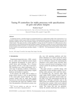
  • 5. Ibrahim Kaya / ISA Transactions 43 (2004) 297–304 301 Fig. 5. Control signals for example 1. Fig. 4. Step responses for example 1. that with the proposed design method less effort is 4. Simulation examples required for the control action, for both design methods. Several examples are presented to illustrate the Example 2: In this example, a real industrial use of the proposed method. Since the presented HVAC system used in Wang et al. ͓3͔ with trans- design method is model based, the identification fer function of G ( s ) ϭe Ϫ2s / ( 0.12s 2 ϩ1.33s method given by Kaya ͓7͔ or Kaya and Atherton ϩ1.24) is considered. The FOPDT model was ob- ͓8͔ has been used to find the FOPDT model. The tained as G ( s ) ϭ0.81e Ϫ2.78s / ( 1.011sϩ1 ) , using identification method has been used for all transfer the estimation method given in Refs. ͓7,8͔. The PI functions in the examples but since it gives essen- controller parameters are K p ϭ0.235 and T i tially exact results on simulation data the esti- ϭ1.011, when Eqs. ͑18͒ and ͑19͒ are used in con- mated plant transfer functions are only given for junction with Eq. ͑31͒. The PID controller param- original plants of higher order. In all the examples, eters used by Wang et al. ͓3͔ are K p ϭ0.611, T i controllers, for both the proposed design method ϭ1.441, and T d ϭ0.564. The response of the and design methods that are used for comparison, closed-loop system with designed controllers for are designed for a gain and phase margin of 3 and both design methods to a unity step set-point 60°, respectively. change together with load disturbance introduced Example 1: Consider a second-order plus dead at time 30 s are given in Fig. 6. The assumed load time plant transfer function of G ( s ) ϭe Ϫ1.0s / ( s disturbance magnitude was Ϫ0.5. In terms of ϩ1 )( 0.5sϩ1 ) , which was given in Ref. ͓1͔. The identification method given in Refs. ͓7,8͔ was used to obtain the FOPDT model as G ( s ) ϭe Ϫ1.34s / ( 1.44sϩ1 ) . Therefore the PI controller parameters are obtained from Eqs. ͑18͒ and ͑19͒, in conjunction with Eq. ͑31͒, to be K p ϭ0.563 and T i ϭ1.44. The controller parameters for the design method proposed by Ho et al. ͓1͔ are K p ϭ0.52, T i ϭ1.00, and T d ϭ0.50. The closed-loop re- sponses for both design methods are given in Fig. 4 for a unity step set-point change and a distur- bance with magnitude of Ϫ0.5 introduced at time 30 s. As is seen from the figure, the proposed de- sign method results in a better performance for both the set-point response and disturbance rejec- tion. Fig. 5 illustrates control signals, which show Fig. 6. Step responses for example 2.
  • 6. 302 Ibrahim Kaya / ISA Transactions 43 (2004) 297–304 Fig. 8. Step responses for example 3. Fig. 7. Control signals for example 2. illustrates that with the proposed method less ef- fort is necessary for the control action. maximum overshoot, the proposed design method Example 4: A high-order oscillating plant trans- gives better performance than the design method fer function of G ( s ) ϭe Ϫs / ( s 2 ϩsϩ1 )( sϩ3 ) , proposed by Wang et al. ͓3͔ for the set-point re- which was used by Wang and Shao ͓4͔, is consid- sponse. In terms of settling time, both design ered. Again, the parameter estimation method methods give similar responses. The load distur- given in Refs. ͓7,8͔ was employed to generate the bance rejection of the design method suggested by FOPDT model as G ( s ) ϭ0.333e Ϫ3.1s / ( 0.075s Wang et al. ͓3͔ is slightly faster than the proposed ϩ1 ) . Once a proper model is found, the PI con- one. This is expected, since in the proposed design troller tuning parameters were calculated to be method pole zero cancellations are used and this in K p ϭ0.038 and T i ϭ0.075. Wang and Shao sug- some cases may lead to a sluggish load distur- gested a PID controller with settings of K p bance rejection. However, when comparing the ϭ1.298, T i ϭ1.034, and T d ϭ1.017. With these control signals, shown in Fig. 7, it is seen that the calculated controller settings, the step response of proposed design method requires less attempt for the closed-loop system to a unity step set-point the control action. change and a disturbance of magnitude of Ϫ0.5 Example 3: A high-order plant transfer function introduced at time 50 s is shown in Fig. 10. Again, of G ( s ) ϭ1/( sϩ1 ) 8 , which was given in Wang the proposed design method results in a better per- and Shao ͓4͔, is considered in this example. The formance, especially for set point response. In Fig. identification method given in Refs. ͓7,8͔ was 11, control signals for both design methods are used to find the FOPDT model, G ( s ) ϭe Ϫ5.10s / ( 4.35sϩ1 ) . Using Eqs. ͑18͒ and ͑19͒ together with Eq. ͑31͒, the PI controller settings were found to be K p ϭ0.447 and T i ϭ4.340. The PID controller parameters suggested by Wang and Shao ͓4͔ are K p ϭ0.677, T i ϭ4.340, and T d ϭ1.649. Fig. 8 illustrates responses for both de- sign methods to a unity set-point change together with load disturbance introduced at time 80 s. The load disturbance magnitude was again assumed to be Ϫ0.5. The proposed design method, as is seen from Fig. 8, results in a better closed-loop system performance in terms of maximum overshoot, while in terms of the settling time both designs give quite similar performances. Control signals for this example are given in Fig. 9, which again Fig. 9. Control signals for example 3.
  • 7. Ibrahim Kaya / ISA Transactions 43 (2004) 297–304 303 controller may lead to sluggish load disturbance rejection, again due to pole zero cancellation used in the design procedure. However, in the examples given in this paper, it is seen that the load distur- bance rejection of the proposed design method is also satisfactory. Appendix: Model identification In this section, equations used to identify the unknown parameters of the FOPDT plant transfer function are given. The identification method Fig. 10. Step responses for example 4. makes use of the relay autotuning. The given equations will result in exact parameter estima- tions, assuming no measurement errors. The de- given. Again, it is seen that the process can be tails can be found in Refs. ͓7,8͔. controlled with less effort by the proposed design Two equations for the limit cycle frequency ␻ method. and the pulse duration ⌬t 1 can be obtained and are given by ͩ ͪ 5. Conclusions Ϫ ␻ ⌬t 1 ␲ ͑ e ⌬t 1 /T Ϫ1 ͒ e ␪ /T Simple tuning rules for a PI controller for con- K ϩ 2 ͑ e 2 ␲ /␭ Ϫ1 ͒ trolling stable process with small time delays have been derived using specified gain and phase mar- gin specifications. The design method presented in this paper is model based. Therefore first a ϭ ͩ ␲ h 1 Ϫh 2 ͪͩ RϪ⌬Ϫ G ͑ 0 ͓͒ h 1 ⌬t 1 ϩh 2 ⌬t 2 ͔ P ͪ FOPDT plant transfer function model was ob- ͑A1͒ tained from a single relay feedback test with exact and ͩ ͪ limit cycle analysis. Once the model was found, simple tuning rules provided in the paper were ␻ ⌬t 1 Ϫ2 ␲ ␲ ͑ e ͑ Ϫ ␻ ⌬t 1 ϩ2 ␲ ͒ /␭ Ϫ1 ͒ e ␪ /T used to control the process. Since the proposed K ϩ design method incorporates IMC design prin- 2 ͑ e 2 ␲ /␭ Ϫ1 ͒ ͩ ͪͩ ͪ ciples, where pole zero cancellation is used, the Ϫ␲ G ͑ 0 ͓͒ h 1 ⌬t 1 ϩh 2 ⌬t 2 ͔ closed-loop system with designed PI controller re- ϭ Rϩ⌬Ϫ , sults in good set point responses. The designed h 1 Ϫh 2 P ͑A2͒ where h 1 and h 2 are the relay heights and ⌬ is the hysteresis. ⌬t 1 and ⌬t 2 are the pulse durations and Pϭ⌬t 1 ϩ⌬t 2 is the period of the oscillation. R is a constant valued signal entering the system and ␭ϭ ␻ T. Two more equations can be obtained for the maximum and minimum of the plant output wave form which are given by the following equations: a minϭ G ͑ 0 ͓͒ h 1 ⌬t 1 ϩh 2 ⌬t 2 ͔ P ϩ ͩ h 1 Ϫh 2 ␲ ͪ Fig. 11. Control signals for example 4. ϫ ͩ Ϫ ␻ ⌬t 1 ␲ ͑ e ⌬t 1 /T Ϫ1 ͒ 2 ϩ ͑ e 2 ␲ /␭ Ϫ1 ͒ ͪ ͑A3͒
  • 8. 304 Ibrahim Kaya / ISA Transactions 43 (2004) 297–304 and either Eq. ͑A3͒ if a min is measured or Eq. ͑A4͒ if ͩ ͪ a max is measured. Finally, with K and T known, G ͑ 0 ͓͒ h 1 ⌬t 1 ϩh 2 ⌬t 2 ͔ h 1 Ϫh 2 a maxϭ ϩ the dead time ␪ can be calculated from either Eq. P ␲ ͑A1͒ or Eq. ͑A2͒. ϫ ͩ Ϫ ␻ ⌬t 1 ␲ e 2 ␲ /␭ ͑ 1Ϫe Ϫ⌬t 1 /T ͒ 2 ϩ ͑ e 2 ␲ /␭ Ϫ1 ͒ . ͪ References ͓1͔ Ho, W. K., Hang, C. C., and Cao, L., Tuning of PID controllers based on gain and phase margin specifica- ͑A4͒ tions. Automatica 31, 497–502 ͑1995͒. ͓2͔ Fung, H. W., Wang, Q. G., and Lee, T. H., PI Tuning Although Eqs. ͑A1͒–͑A4͒ obtained for a stable in terms of gain and phase margins. Automatica 34, FOPDT transfer function are sufficient to identify 1145–1149 ͑1998͒. ͓3͔ Wang, Q. G., Fung, H. W., and Zhang, Y., PID tuning the unknown parameters, K, T, and ␪, initial with exact gain and phase margins. ISA Trans. 38, guesses are required for the unknowns to solve 243–249 ͑1999͒. these nonlinear equations. To reduce the number ͓4͔ Wang, Y. G. and Shao, H. H., PID autotuner based on of unknowns and make the solution easier to find, gain- and phase-margin specifications. Ind. Eng. Chem. Res. 38, 3007–3012 ͑1999͒. Fourier analysis can be used to identify the steady- ͓5͔ Rivera, D. E., Morari, M., and Sigurd, S., Internal state gain K from model control. 4. PID controller design. Ind. Eng. Chem. Process Des. Dev. 25, 252–265 ͑1986͒. ͵ c͑ t ͒dt 0 P ͓6͔ Morari, M. and Zafiriou, E., Robust Process Control. Prentice-Hall, Englewood Cliffs, NJ, 1989. KϭG ͑ 0 ͒ ϭ ͑A5͒ ͓7͔ Kaya, I., Relay feedback identification and model ͵ y ͑ t ͒dt P , based controller design. Ph.D. thesis, University of 0 Sussex, U.K., 1999. ͓8͔ Kaya, I. and Atherton, D. P., Parameter estimation where c ( t ) is the plant output, y ( t ) is the relay from relay autotuning with asymmetric limit cycle data. J. Process Control 11, 429– 439 ͑2001͒. output, and P is the period. ˚ ¨ ͓9͔ Astrom, K. J. and Hagglund, T., PID Controllers: ¨ Once the steady-state gain K is obtained from Theory, Design and Tuning. Instrument Society of Eq. ͑A5͒, the time constant T can be obtained from America, Research Triangle Park, NC, 1995.