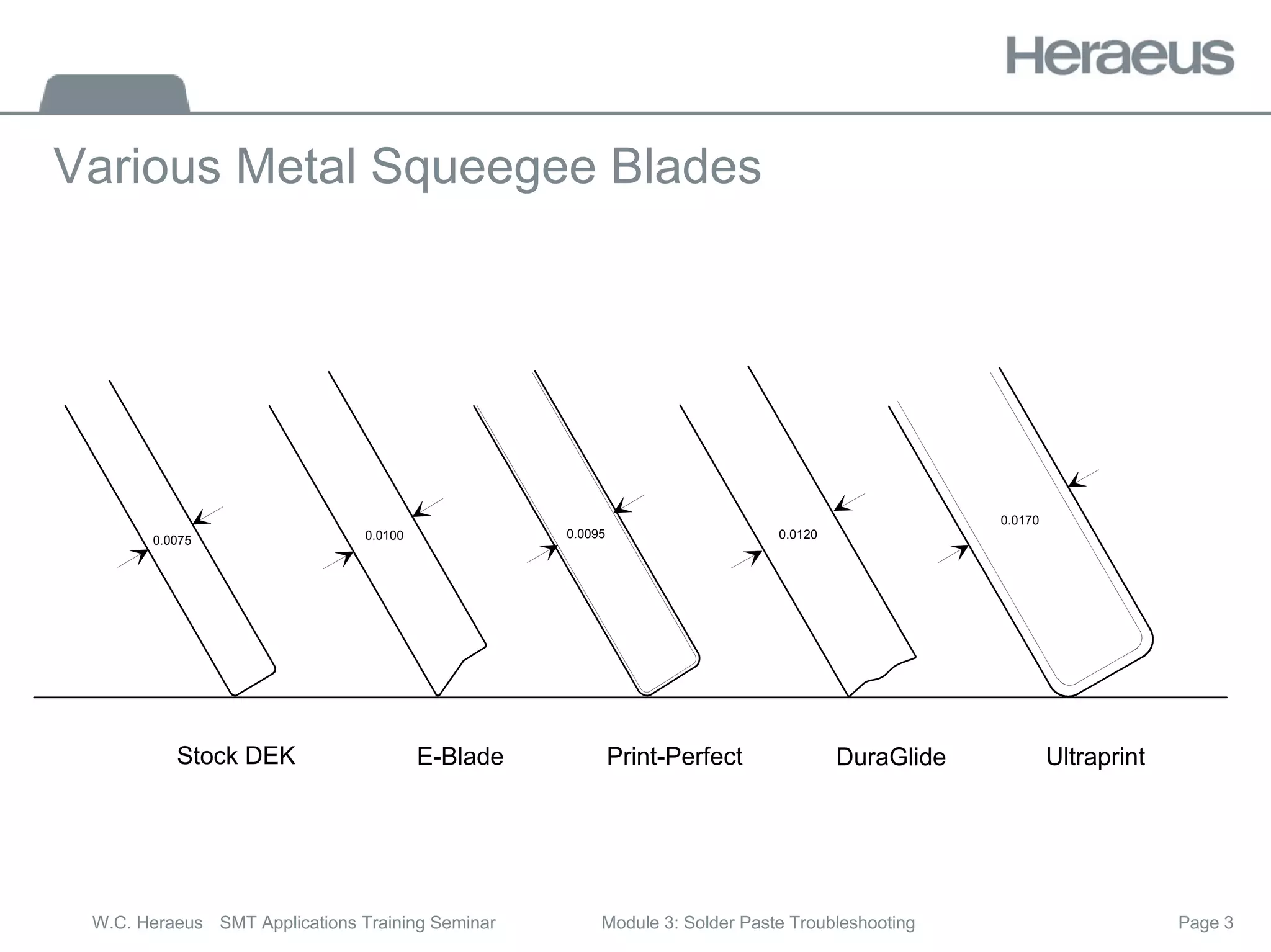
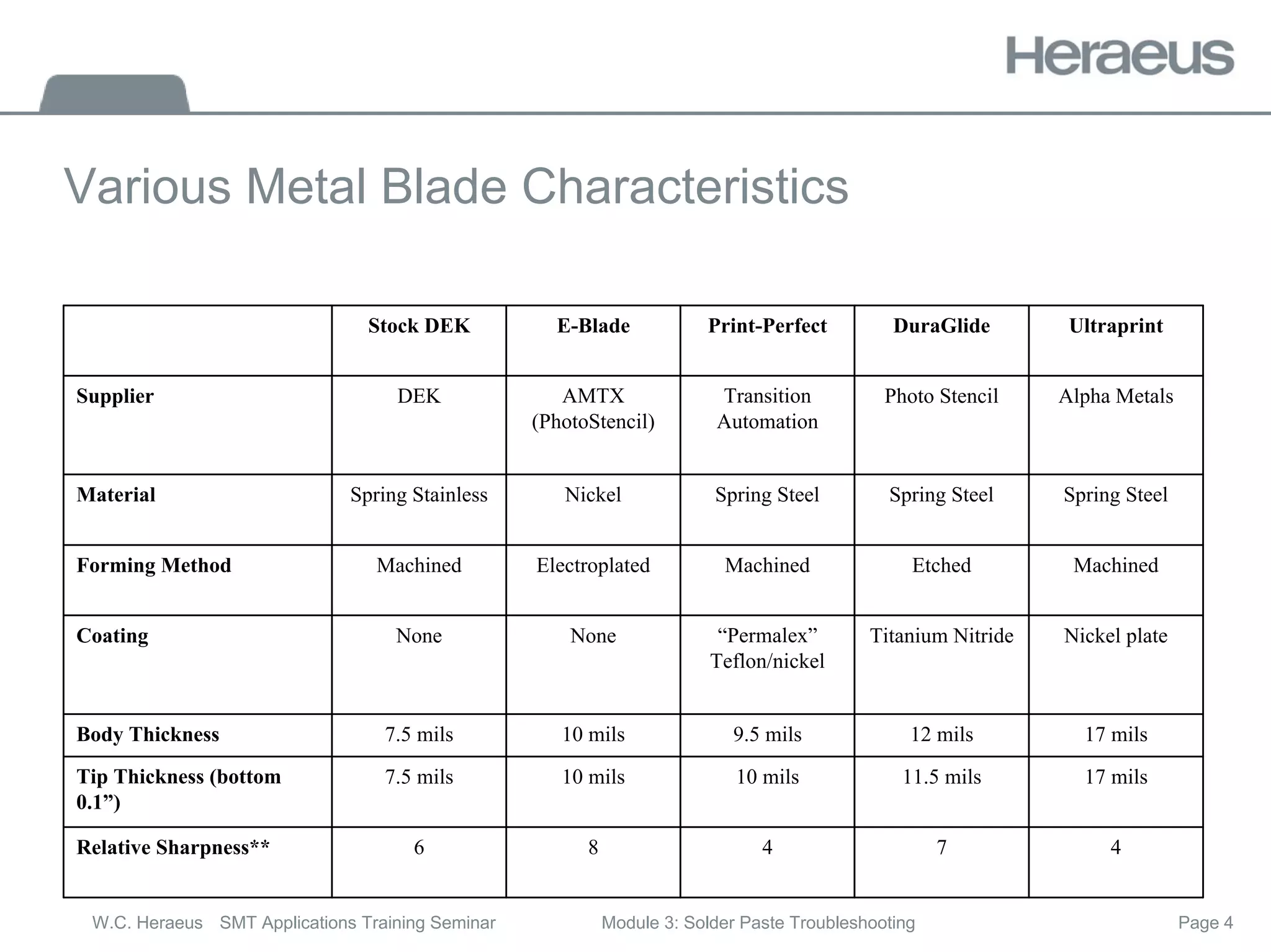
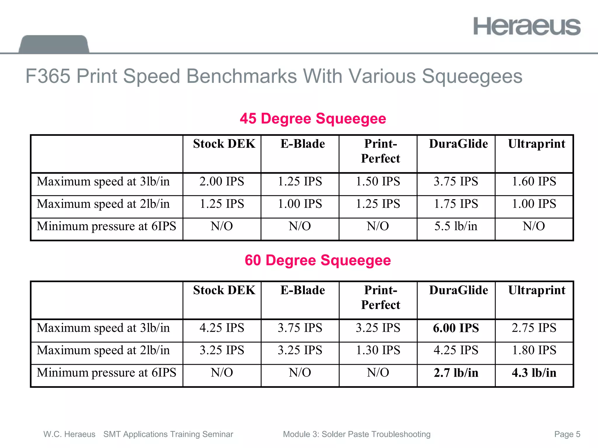
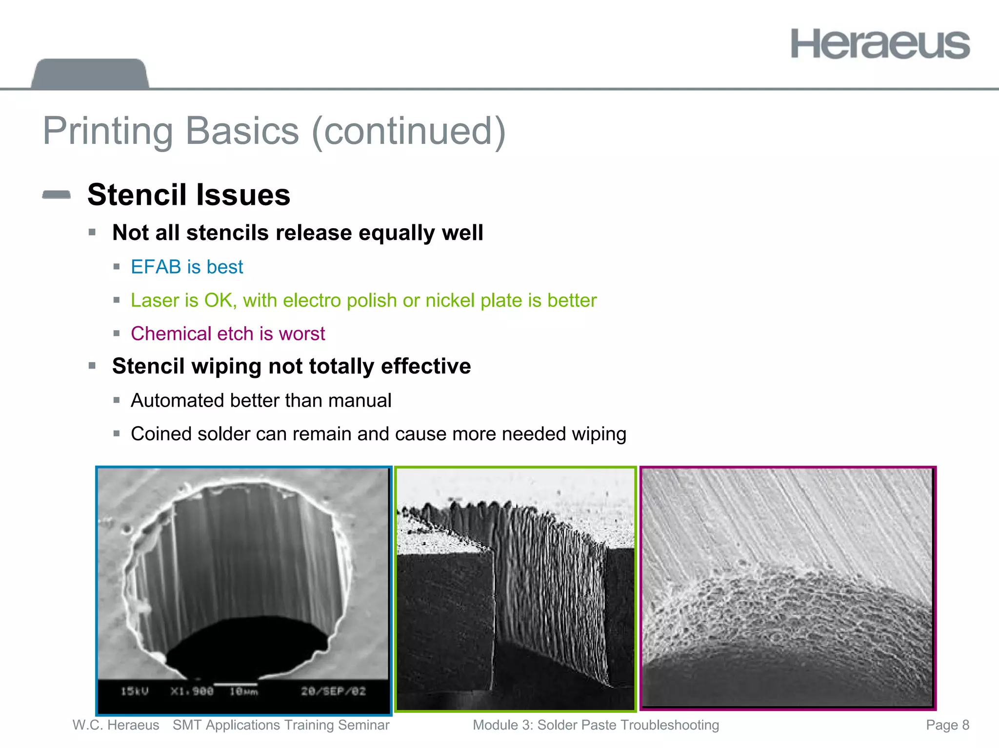
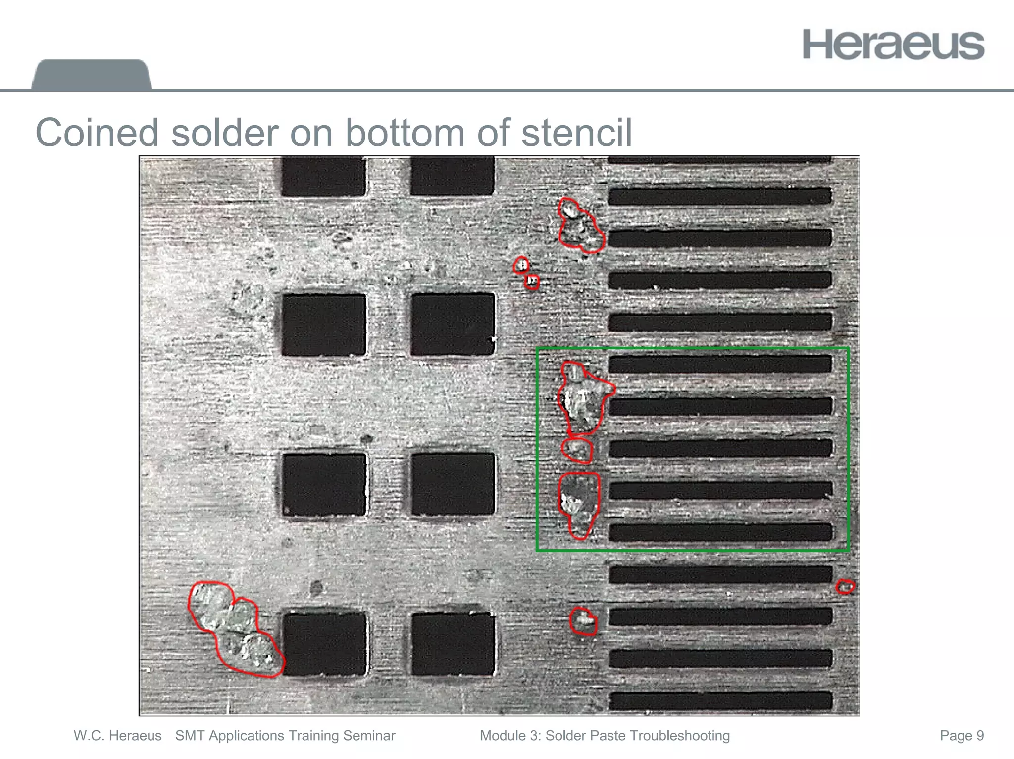
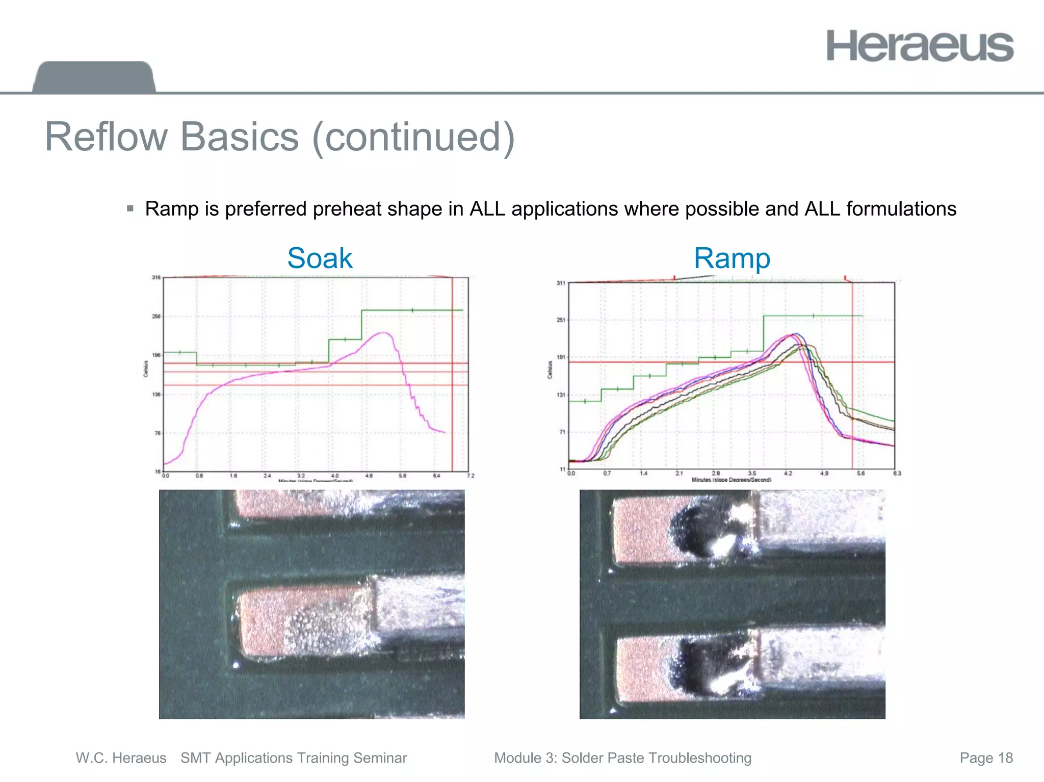
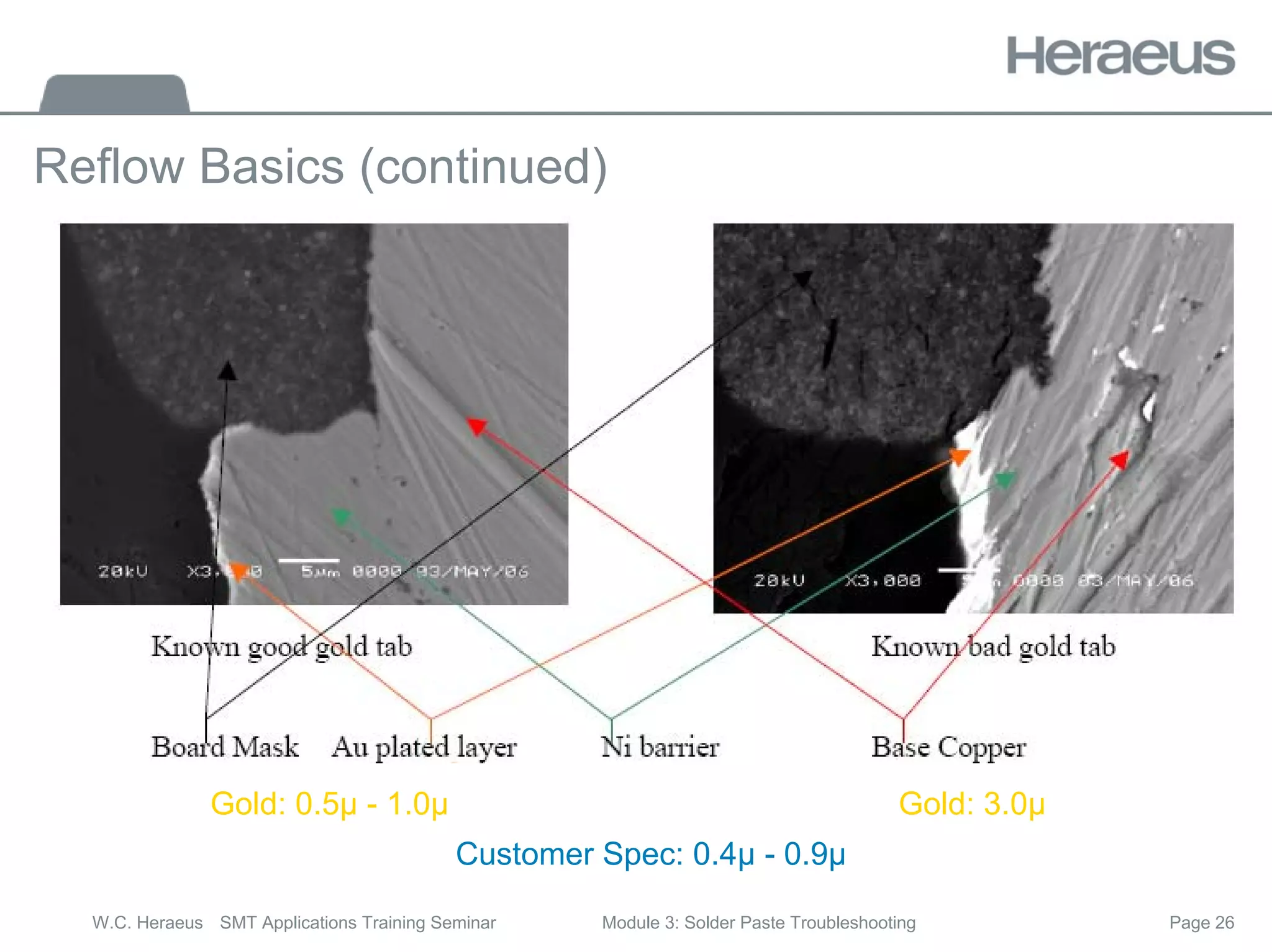
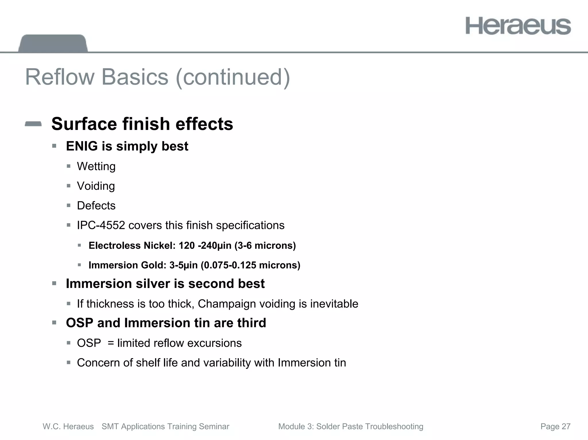
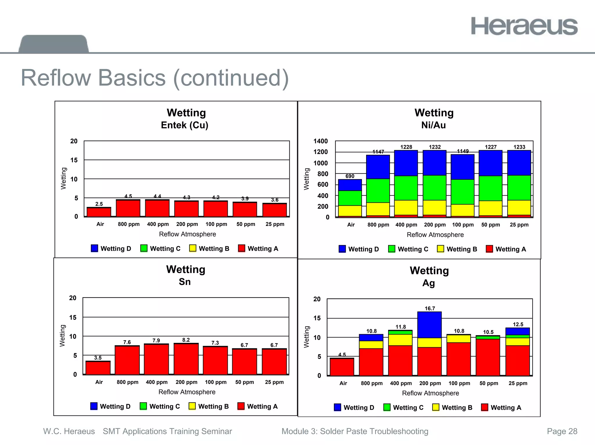
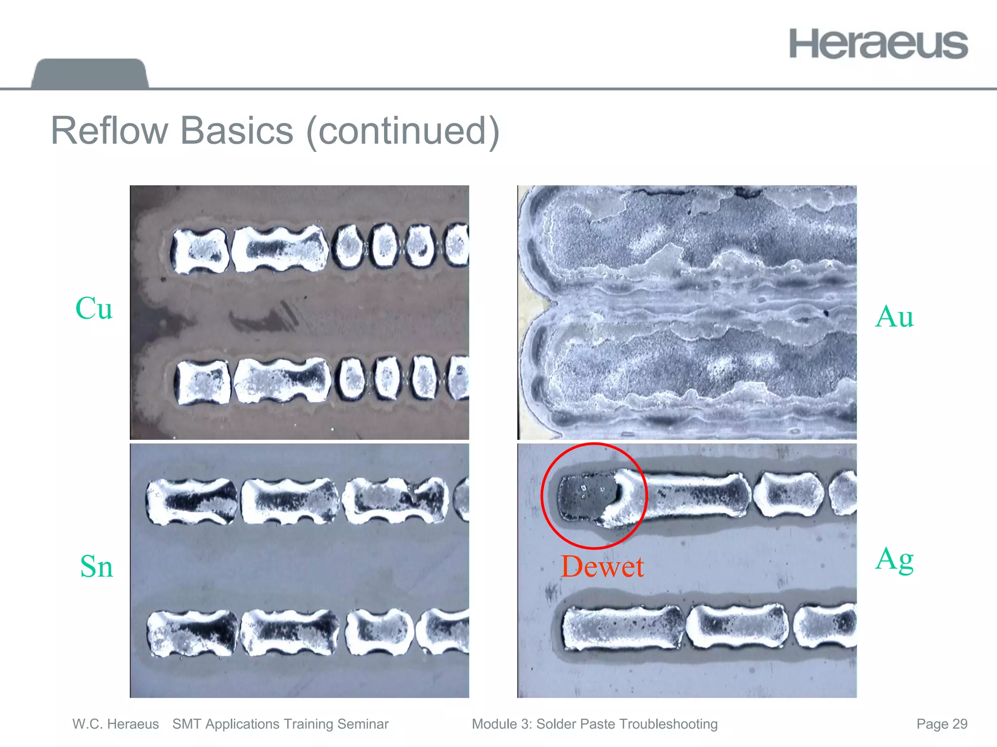
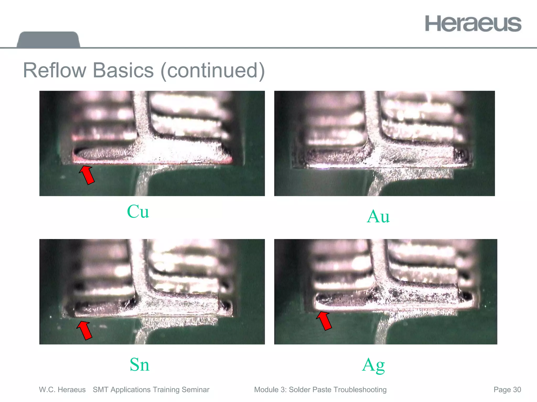
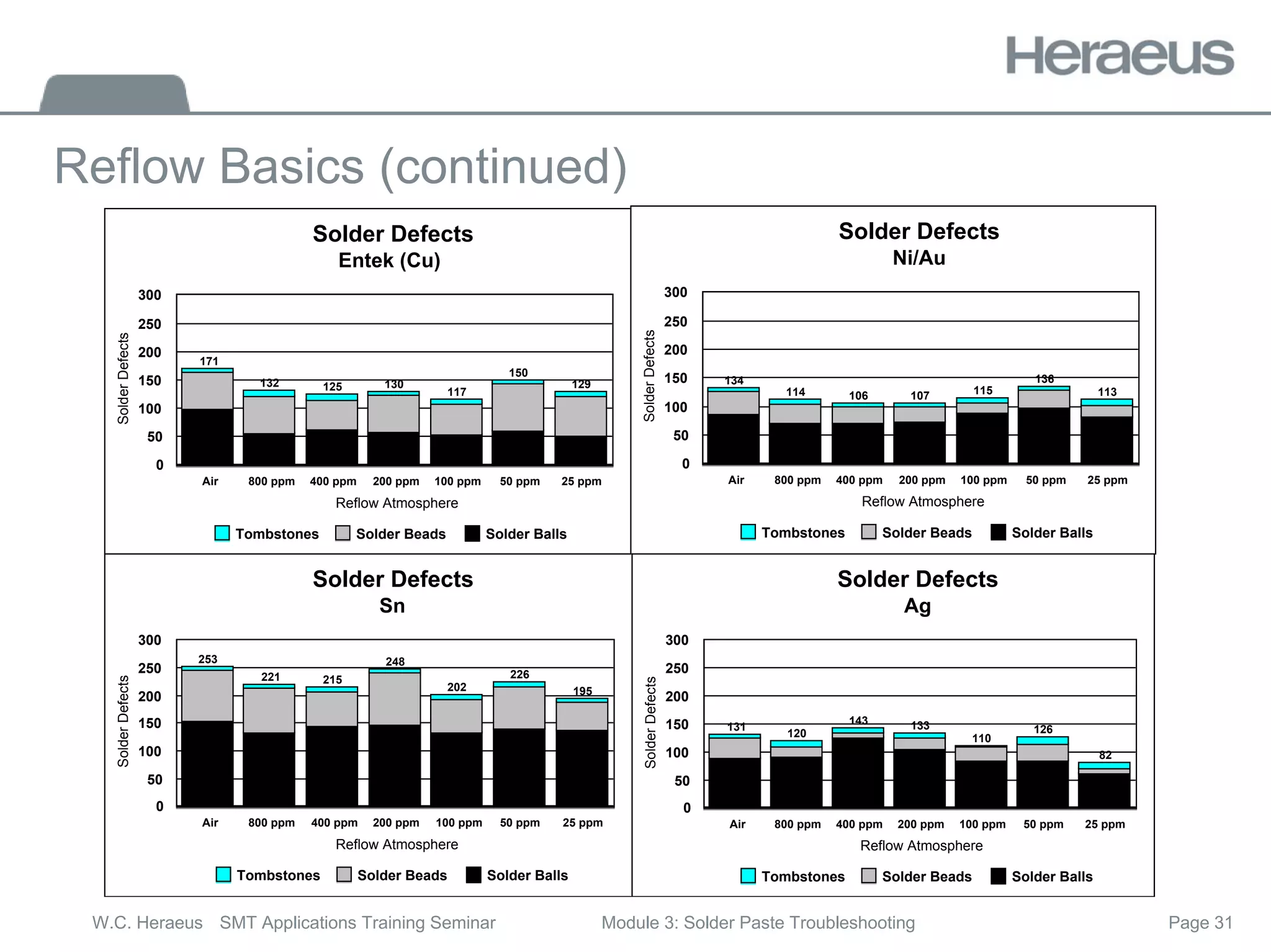
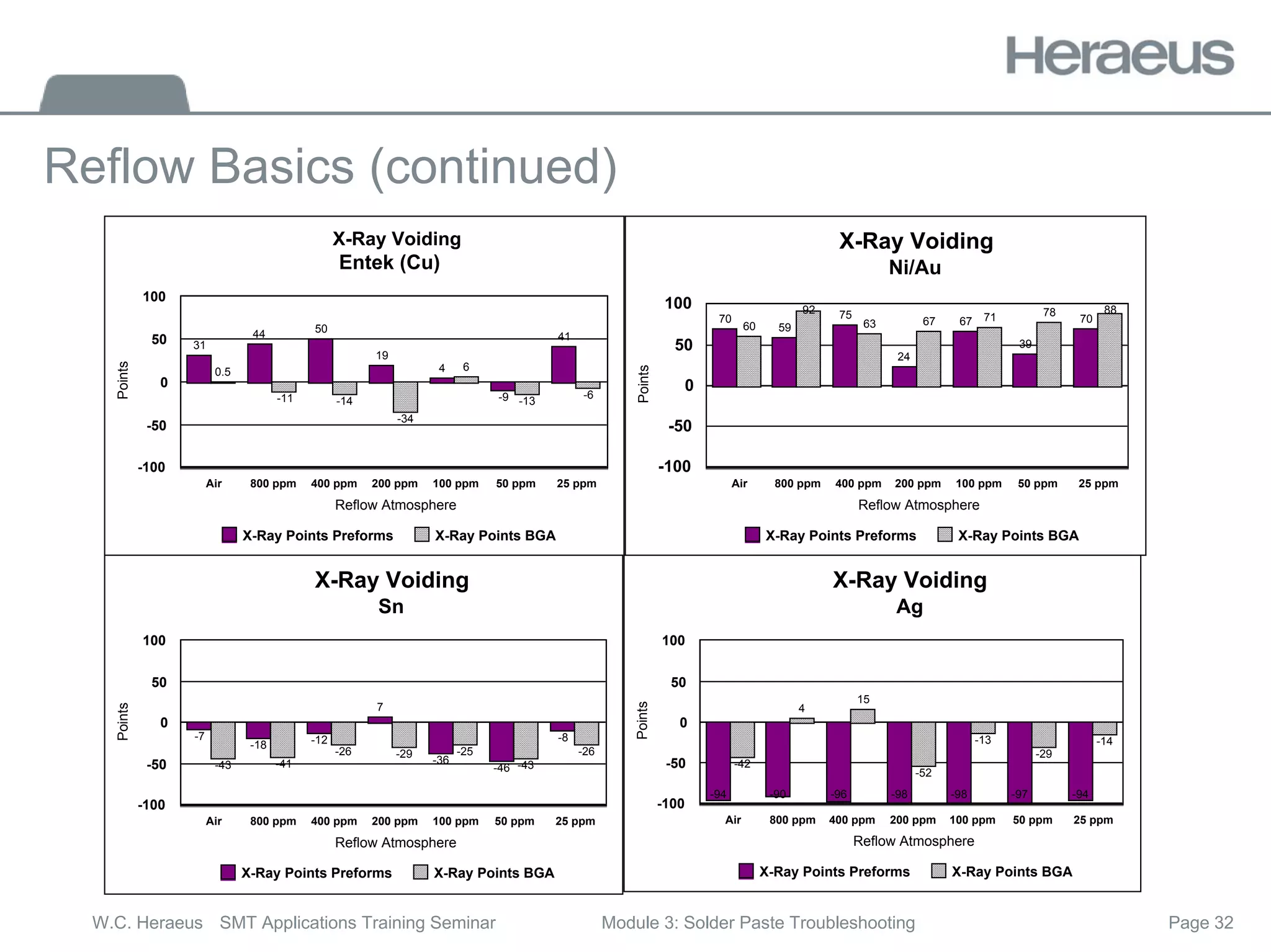
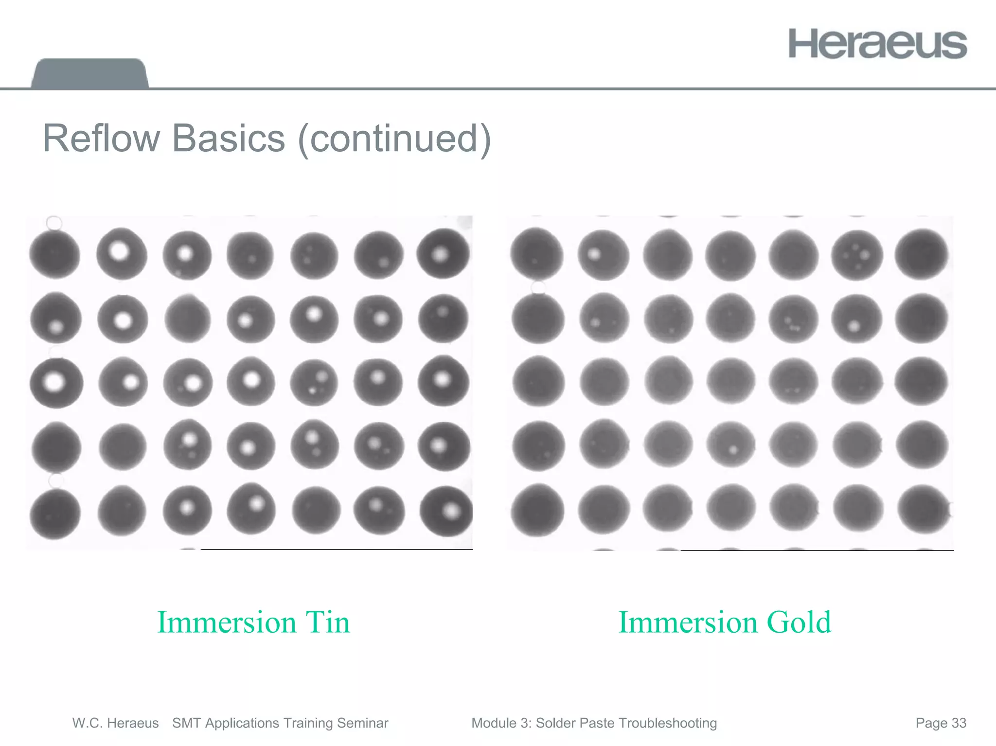
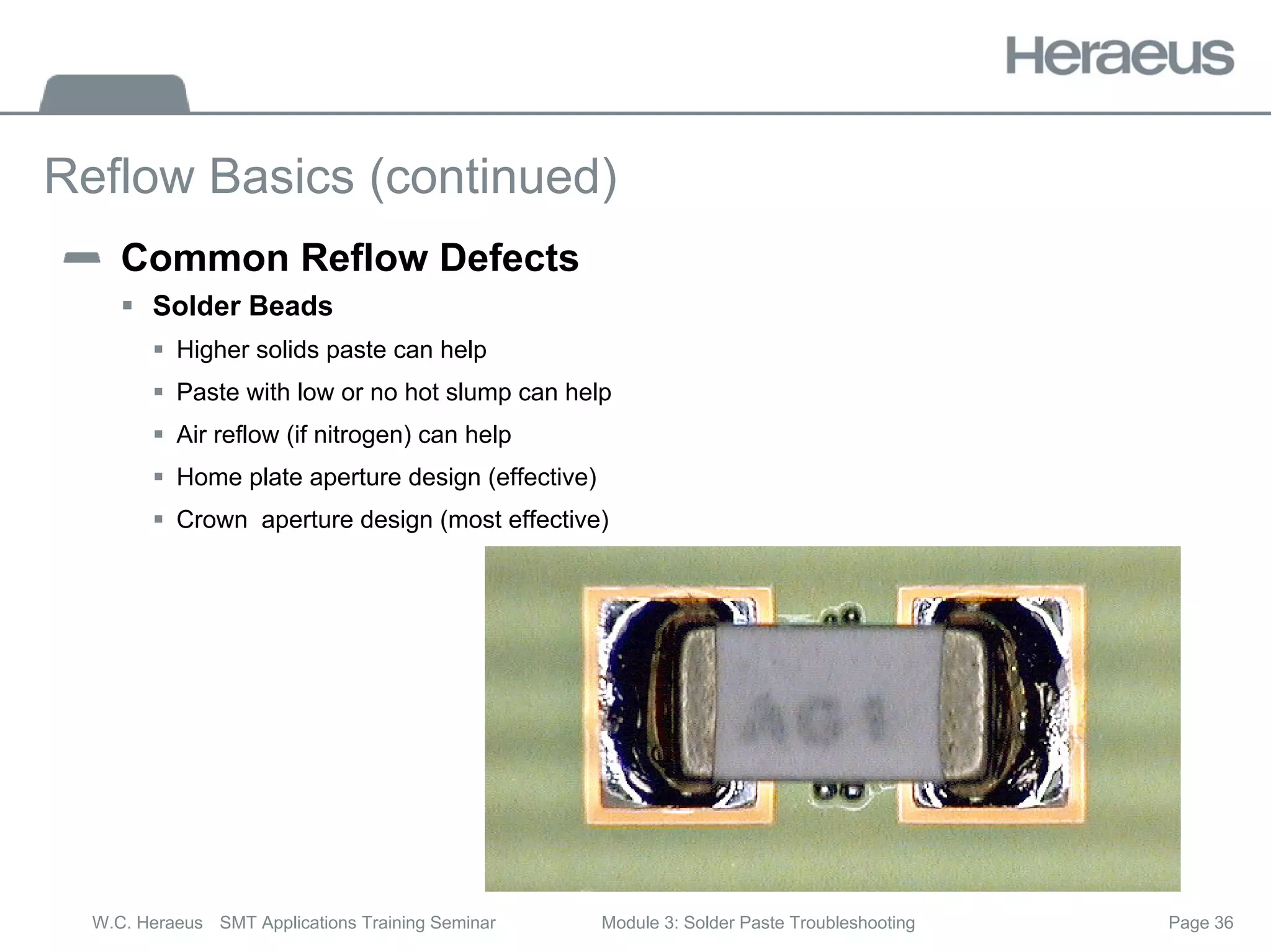
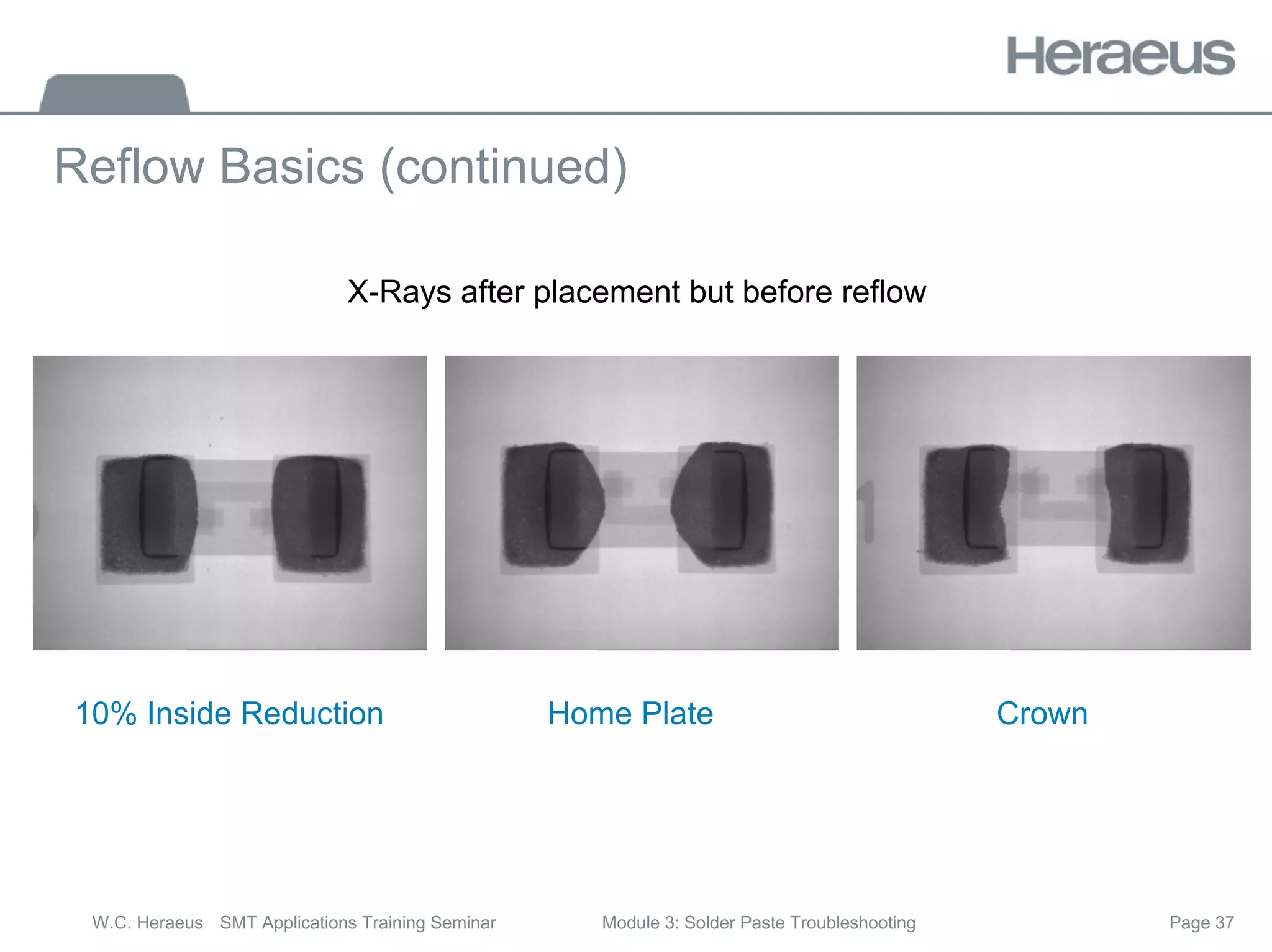
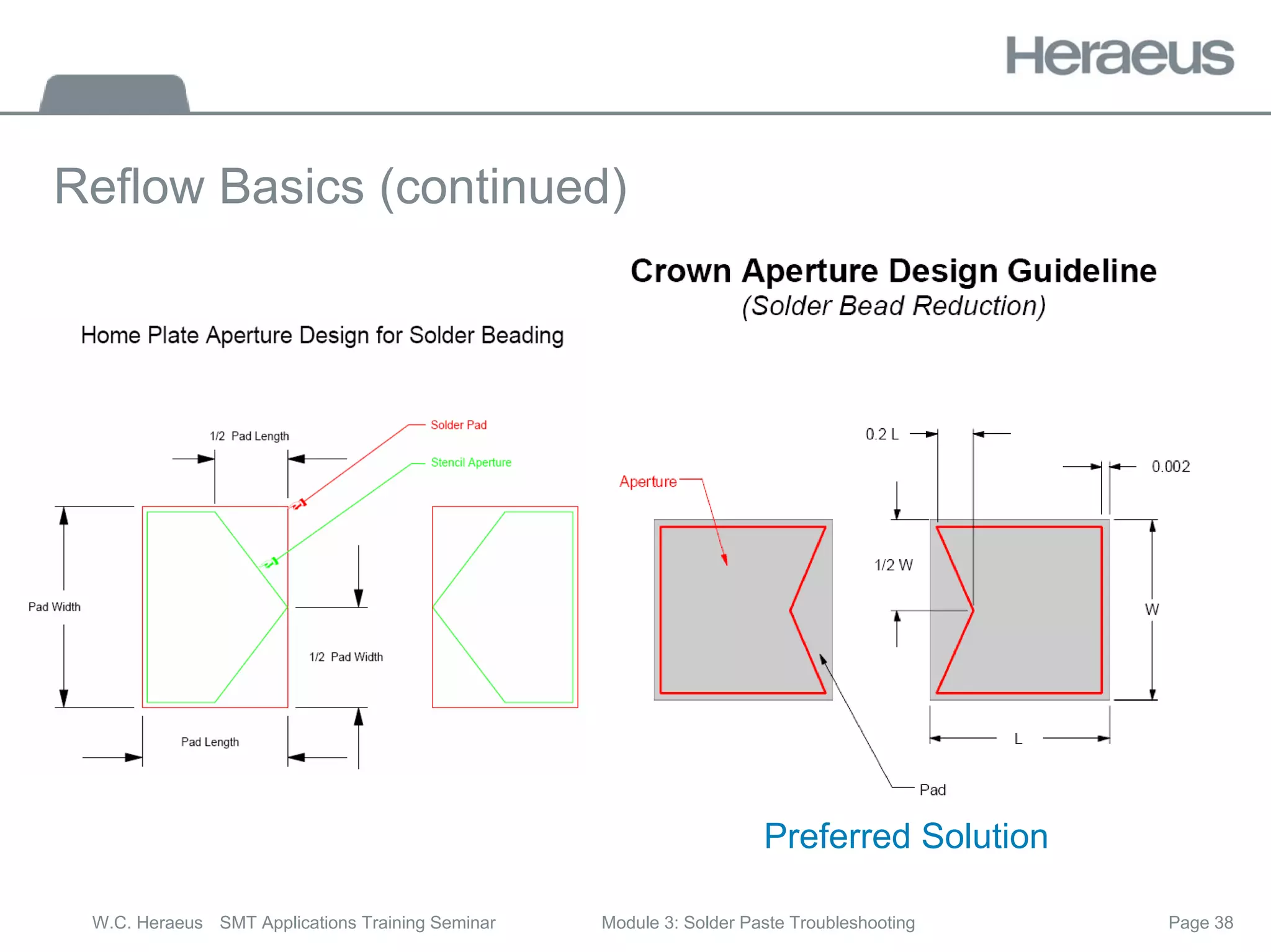
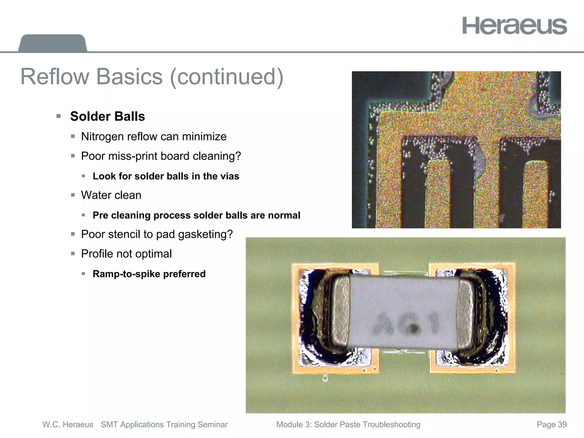
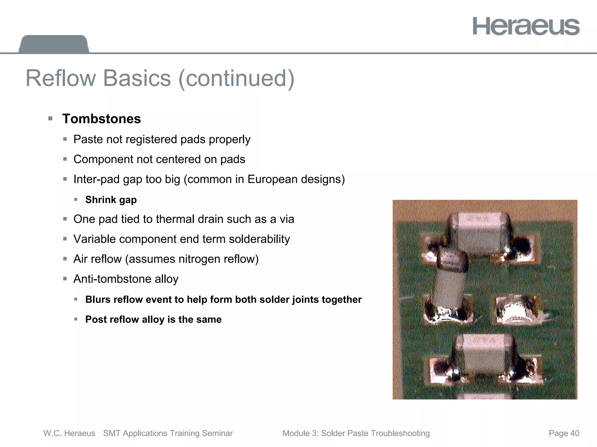
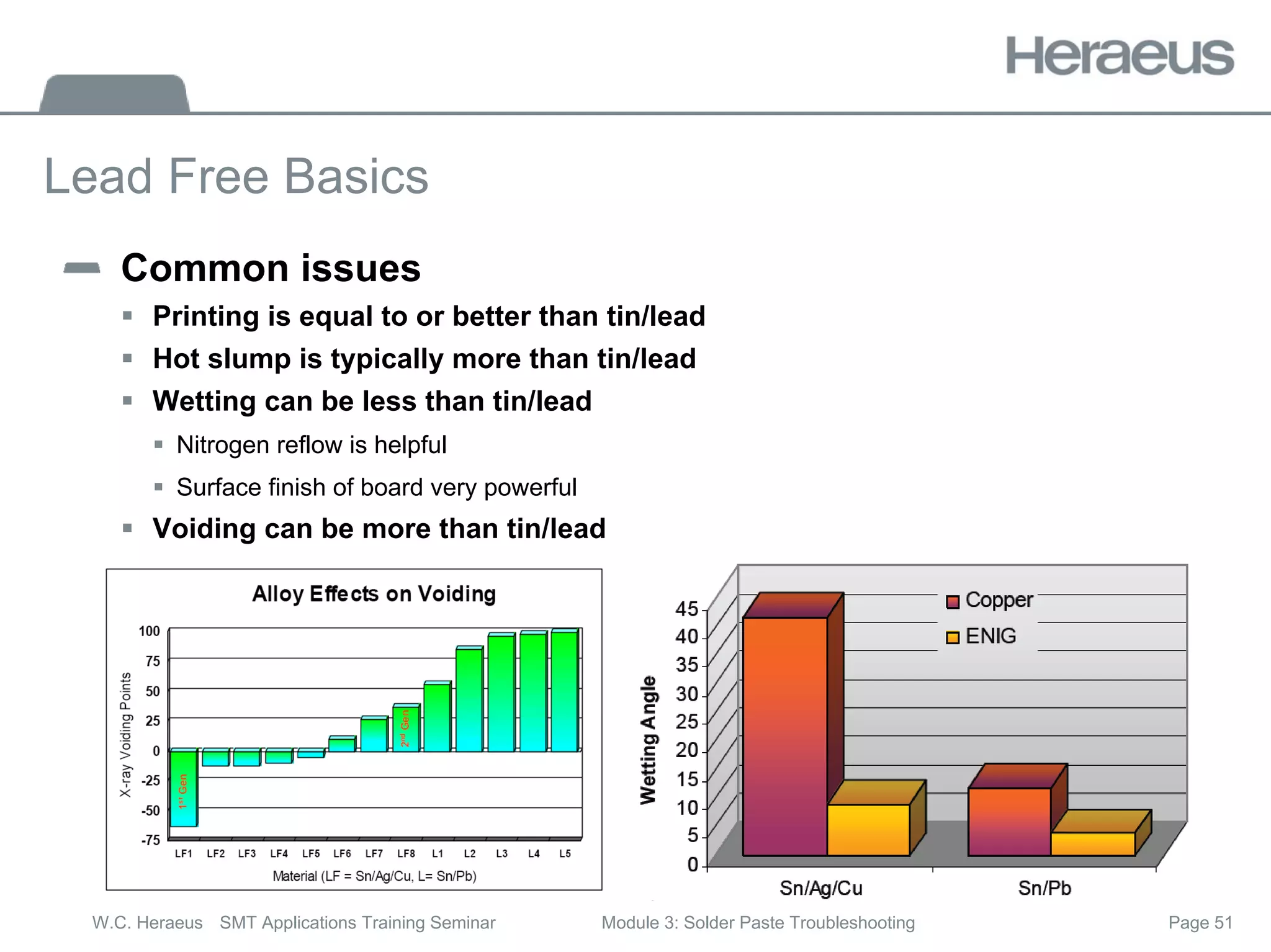
This document discusses solder paste printing and reflow troubleshooting. It provides details on different squeegee types and their effects on printing speed. Compaction issues that can occur are described, along with factors affecting preheat shape and profile. Wetting issues are explored, such as effects of component finishes, gold content, and reflow atmosphere. Defects like tombstones and head-in-pillow are explained. Overall it provides an overview of solder paste process parameters and how to address common problems.
This training is very necessary to them who are working in Electronics manufacturing because Soldering process is the Heart of Electronics Industry, that's why this training is very important to employees.
LED, BGA, and QFN Inspection - X-Ray Inspection for SMT Quality Assurance and...Bill Cardoso
In this presentation we will cover the manufacturing of the most challenging surface mount parts to assemble and inspect today: LEDs, BGAs, and QFNs. The presentation will focus on the pitfalls of manufacturing and inspecting PCBs with these devices and solution to the technical challenges encountered by luminaire integrators and contract manufacturers. This presentation is targeted at manufacturing, process, and quality personnel responsible for designing; implementing and/or controlling the surface mount device application and inspection process. Those personnel responsible for training operators and technicians to perform assembly inspection or control the manufacturing process would also benefit from this presentation.
How to find defects in SMT electronics manufacturingBill Cardoso
This presentation covers several examples of defects found in today's SMT electronics manufacturing lines. Learn how x-rays can be used to find these defects, and most importantly, diagnose your manufacturing line.
All x-ray images taken with TruView X-Ray Inspection systems.
- Where Are Defects Introduced in the SMT production line?
- Solder Paste Application Defects
- Component Placement Defects
- Reflow Oven Defects
- Statistical Process Control
Project Report on SMT and through-hole technologylakshya bhardwaj
SMT and Through-hole technology and their assembly line, different types of Soldering, ESD protection, Conformal coating, etc, all about PCB Production
We designed and manufactured Auto Insertion machine in Shenzhen China, and provide SMT equipments, spare parts services support.
Please email: jasonwu@smthelp.com
PCBA Assembly Process Flow / PCB Assembly Manufacturing introduces the basic manufacturing process of PCBA / PCB assembly in different condition of component.It is about PCBA manufacture production.
Introduction to Surface Mount TechnologyABDUL MUNAFF
Surface Mount Technology (SMT) refers to a specific type of electronics assembly where electronic components are attached to the surface of a substrate (typically a printed circuit board).
SMT is a modern alternative to traditional thru-hole technology where components are attached to substrates by leads that passed through holes in the PCB.
Surface Mount components require less space so SMT is helpful in product miniaturization.
SMT Overview
SMT V/S THROUGH HOLE
Basic SMT process flow
Equipments used SMT Assembly
Through Hole Assembly & Soldering
ELECTROSTATIC DISCHARGE
RoHS
This slide deck takes you through important elements of manula PCB inspection including some definitions, what makes a good inspector , what type of lighting is required to be able to see the important aspects of a PCB and the types of inspection aids. The slide deck ends with some real examples where the user is challenged to make a determination of defect/process indicator/acceptable of an electronics assembly in accordance with the IPC-A-610 and IPC-A-620 standards.
Prevent time-to-market delays by identifying manufacturing issues before they become a costly mistake. It’s not uncommon for designs to be submitted to manufacturing only to have problems identified that require design reworking and re-submission. This results in lost production time, schedule delays, and recurring tooling costs. What if you could identify DFM problems as you design and fix them when they happen? We will help show you how to spot and fix troublesome DFM issues in-design before they ever become a problem.
Based on on-demand webinar. Watch full recording here: https://resources.ema-eda.com/webinars/on-demand-webinar-design-for-manufacturing-dfm-and-why-it-matters
Under this we have proposed a Lean Manufacturing technique which is named as SMED to reduce the Setup time and Changeover time of the manufacturing process in a heavy machine shop.
The Training is a 1 day course covering impartation knowledge of Kaizen and its associated Tools and; -application of Lean concepts to lead Kaizen Workshop/s with Innovation Projects for Change in a World Class Manufacturing Environment.
This training aims to impart a systematic review on all the critical aspects of Lean use to; lead Kaizen workshop and presentation using Standardize Kaizen form and methodology with;
Innovation to be competitive in the Global Business Environment.
COURSE CONTENT
Kaizen, its definition and Principles
Kaizen definition, Innovation Definition
Kaizen vs Innovation
Characteristics of a Lean Factory
Cellular Factory Layout
Multi-skilled Operators
6S and Visual Control
Kanban and Supermarkets
Rapid Changeover
Total Quality Approach
Right-sized, flexible equipment
Water Strider
Moving Production Lines
Total Productive Maintenance
Continuous Improvement
The 3 Pillars of Kaizen
1. 6S (5+1S) Housekeeping
2. Waste Elimination
- Types of Waste CLOSEDMITT
- Valued-added vs Non-value
added
3. Standard Operation
Three factors that accounts the 3 Pillars Activities.
1. Visual management,
2. The role of the supervisor,
3. Importance of training and
creating a learning
organization.
Innovation & Workshop Projects
Types of Innovation in Kaizen. Why Innovation?
Degree of Innovation-the act of creating new products,
processes, ideas, etc...
Examples of Types of Innovation
Innovating Process using Typical Kaizen concepts (Lean
methods)
Phase 1: Pre-Planning for Innovation
Phase 2: Execution - Innovation Week
Role of Leader, Facilitator, Participant in Innovation
Projects
Innovation Projects Implementation using Kaizen Forms for:
Daily and Weekly Report Outs
Follow-up for further Innovation
it is PDF are typed of myself. study triks & short & sweet (Technical manual) Of Diploma in Plastics technology(DPT-DPMT). All machine knowlage in plastics processing.
Er. Naresh Dhaker
(8890881858)
(CIPET JAIPUR)
AGC's newest additions to its adhesive-grade product lineup provide industry-leading performance across an expanded range of applications in the automotive, oil and gas, chemical, building and construction, packaging and electronics industries. Each is formulated for ease of use within its respective processing environment and is backed by AGC's longstanding reputation as a leading provider of functionalized adhesives.
Water scarcity is the lack of fresh water resources to meet the standard water demand. There are two type of water scarcity. One is physical. The other is economic water scarcity.
Immunizing Image Classifiers Against Localized Adversary Attacksgerogepatton
This paper addresses the vulnerability of deep learning models, particularly convolutional neural networks
(CNN)s, to adversarial attacks and presents a proactive training technique designed to counter them. We
introduce a novel volumization algorithm, which transforms 2D images into 3D volumetric representations.
When combined with 3D convolution and deep curriculum learning optimization (CLO), itsignificantly improves
the immunity of models against localized universal attacks by up to 40%. We evaluate our proposed approach
using contemporary CNN architectures and the modified Canadian Institute for Advanced Research (CIFAR-10
and CIFAR-100) and ImageNet Large Scale Visual Recognition Challenge (ILSVRC12) datasets, showcasing
accuracy improvements over previous techniques. The results indicate that the combination of the volumetric
input and curriculum learning holds significant promise for mitigating adversarial attacks without necessitating
adversary training.
Hybrid optimization of pumped hydro system and solar- Engr. Abdul-Azeez.pdffxintegritypublishin
Advancements in technology unveil a myriad of electrical and electronic breakthroughs geared towards efficiently harnessing limited resources to meet human energy demands. The optimization of hybrid solar PV panels and pumped hydro energy supply systems plays a pivotal role in utilizing natural resources effectively. This initiative not only benefits humanity but also fosters environmental sustainability. The study investigated the design optimization of these hybrid systems, focusing on understanding solar radiation patterns, identifying geographical influences on solar radiation, formulating a mathematical model for system optimization, and determining the optimal configuration of PV panels and pumped hydro storage. Through a comparative analysis approach and eight weeks of data collection, the study addressed key research questions related to solar radiation patterns and optimal system design. The findings highlighted regions with heightened solar radiation levels, showcasing substantial potential for power generation and emphasizing the system's efficiency. Optimizing system design significantly boosted power generation, promoted renewable energy utilization, and enhanced energy storage capacity. The study underscored the benefits of optimizing hybrid solar PV panels and pumped hydro energy supply systems for sustainable energy usage. Optimizing the design of solar PV panels and pumped hydro energy supply systems as examined across diverse climatic conditions in a developing country, not only enhances power generation but also improves the integration of renewable energy sources and boosts energy storage capacities, particularly beneficial for less economically prosperous regions. Additionally, the study provides valuable insights for advancing energy research in economically viable areas. Recommendations included conducting site-specific assessments, utilizing advanced modeling tools, implementing regular maintenance protocols, and enhancing communication among system components.
Hierarchical Digital Twin of a Naval Power SystemKerry Sado
A hierarchical digital twin of a Naval DC power system has been developed and experimentally verified. Similar to other state-of-the-art digital twins, this technology creates a digital replica of the physical system executed in real-time or faster, which can modify hardware controls. However, its advantage stems from distributing computational efforts by utilizing a hierarchical structure composed of lower-level digital twin blocks and a higher-level system digital twin. Each digital twin block is associated with a physical subsystem of the hardware and communicates with a singular system digital twin, which creates a system-level response. By extracting information from each level of the hierarchy, power system controls of the hardware were reconfigured autonomously. This hierarchical digital twin development offers several advantages over other digital twins, particularly in the field of naval power systems. The hierarchical structure allows for greater computational efficiency and scalability while the ability to autonomously reconfigure hardware controls offers increased flexibility and responsiveness. The hierarchical decomposition and models utilized were well aligned with the physical twin, as indicated by the maximum deviations between the developed digital twin hierarchy and the hardware.
Overview of the fundamental roles in Hydropower generation and the components involved in wider Electrical Engineering.
This paper presents the design and construction of hydroelectric dams from the hydrologist’s survey of the valley before construction, all aspects and involved disciplines, fluid dynamics, structural engineering, generation and mains frequency regulation to the very transmission of power through the network in the United Kingdom.
Author: Robbie Edward Sayers
Collaborators and co editors: Charlie Sims and Connor Healey.
(C) 2024 Robbie E. Sayers
Saudi Arabia stands as a titan in the global energy landscape, renowned for its abundant oil and gas resources. It's the largest exporter of petroleum and holds some of the world's most significant reserves. Let's delve into the top 10 oil and gas projects shaping Saudi Arabia's energy future in 2024.
Welcome to WIPAC Monthly the magazine brought to you by the LinkedIn Group Water Industry Process Automation & Control.
In this month's edition, along with this month's industry news to celebrate the 13 years since the group was created we have articles including
A case study of the used of Advanced Process Control at the Wastewater Treatment works at Lleida in Spain
A look back on an article on smart wastewater networks in order to see how the industry has measured up in the interim around the adoption of Digital Transformation in the Water Industry.
About
Indigenized remote control interface card suitable for MAFI system CCR equipment. Compatible for IDM8000 CCR. Backplane mounted serial and TCP/Ethernet communication module for CCR remote access. IDM 8000 CCR remote control on serial and TCP protocol.
• Remote control: Parallel or serial interface.
• Compatible with MAFI CCR system.
• Compatible with IDM8000 CCR.
• Compatible with Backplane mount serial communication.
• Compatible with commercial and Defence aviation CCR system.
• Remote control system for accessing CCR and allied system over serial or TCP.
• Indigenized local Support/presence in India.
• Easy in configuration using DIP switches.
Technical Specifications
Indigenized remote control interface card suitable for MAFI system CCR equipment. Compatible for IDM8000 CCR. Backplane mounted serial and TCP/Ethernet communication module for CCR remote access. IDM 8000 CCR remote control on serial and TCP protocol.
Key Features
Indigenized remote control interface card suitable for MAFI system CCR equipment. Compatible for IDM8000 CCR. Backplane mounted serial and TCP/Ethernet communication module for CCR remote access. IDM 8000 CCR remote control on serial and TCP protocol.
• Remote control: Parallel or serial interface
• Compatible with MAFI CCR system
• Copatiable with IDM8000 CCR
• Compatible with Backplane mount serial communication.
• Compatible with commercial and Defence aviation CCR system.
• Remote control system for accessing CCR and allied system over serial or TCP.
• Indigenized local Support/presence in India.
Application
• Remote control: Parallel or serial interface.
• Compatible with MAFI CCR system.
• Compatible with IDM8000 CCR.
• Compatible with Backplane mount serial communication.
• Compatible with commercial and Defence aviation CCR system.
• Remote control system for accessing CCR and allied system over serial or TCP.
• Indigenized local Support/presence in India.
• Easy in configuration using DIP switches.
2. Page 2
W.C. Heraeus SMT Applications Training Seminar Module 3: Solder Paste Troubleshooting
Printing Basics
Print speed and Squeegee pressure are inter-related
ƒ Factors effecting speed
ƒ Temperature
ƒ Cold = slow as pastes are very temperature sensitive
ƒ Squeegee Material
ƒ Polymer is faster than metal
ƒ Poly is simply a better squeegee (windshield wipers)
ƒ Poly wears very quickly, not common today
ƒ Sharpness
ƒ Not all metal squeegees are equal
ƒ Plating of Transition Automation is round and dull
ƒ Angle
ƒ 60 degree is faster than 45 degree
ƒ Watch out for MPM; long blades = low angles with high pressures
3. Page 3
W.C. Heraeus SMT Applications Training Seminar Module 3: Solder Paste Troubleshooting
Various Metal Squeegee Blades
0.0100
0.0075
0.0095 0.0120
Stock DEK E-Blade Print-Perfect DuraGlide
0.0170
Ultraprint
4. Page 4
W.C. Heraeus SMT Applications Training Seminar Module 3: Solder Paste Troubleshooting
Various Metal Blade Characteristics
Stock DEK E-Blade Print-Perfect DuraGlide Ultraprint
Supplier DEK AMTX
(PhotoStencil)
Transition
Automation
Photo Stencil Alpha Metals
Material Spring Stainless Nickel Spring Steel Spring Steel Spring Steel
Forming Method Machined Electroplated Machined Etched Machined
Coating None None “Permalex”
Teflon/nickel
Titanium Nitride Nickel plate
Body Thickness 7.5 mils 10 mils 9.5 mils 12 mils 17 mils
Tip Thickness (bottom
0.1”)
7.5 mils 10 mils 10 mils 11.5 mils 17 mils
Relative Sharpness** 6 8 4 7 4
5. Page 5
W.C. Heraeus SMT Applications Training Seminar Module 3: Solder Paste Troubleshooting
F365 Print Speed Benchmarks With Various Squeegees
Stock DEK E-Blade Print-
Perfect
DuraGlide Ultraprint
Maximum speed at 3lb/in 4.25 IPS 3.75 IPS 3.25 IPS 6.00 IPS 2.75 IPS
Maximum speed at 2lb/in 3.25 IPS 3.25 IPS 1.30 IPS 4.25 IPS 1.80 IPS
Minimum pressure at 6IPS N/O N/O N/O 2.7 lb/in 4.3 lb/in
Stock DEK E-Blade Print-
Perfect
DuraGlide Ultraprint
Maximum speed at 3lb/in 2.00 IPS 1.25 IPS 1.50 IPS 3.75 IPS 1.60 IPS
Maximum speed at 2lb/in 1.25 IPS 1.00 IPS 1.25 IPS 1.75 IPS 1.00 IPS
Minimum pressure at 6IPS N/O N/O N/O 5.5 lb/in N/O
45 Degree Squeegee
60 Degree Squeegee
6. Page 6
W.C. Heraeus SMT Applications Training Seminar Module 3: Solder Paste Troubleshooting
Printing Basics (continued)
ƒ Stencil Roughness
ƒ Rougher better for roll
ƒ Rougher requires more pressure for clean wipe
ƒ Etched or lasered foil is more rougher than EFAB
ƒ Paste factors
ƒ Higher viscosity usually equates to slower print speed and higher pressure.
ƒ Higher tackiness usually equates to slower print speed and higher pressure.
ƒ Squeegee pressure take away message
ƒ “Apply minimum pressure to get a clean wipe, (no solder powder) around the apertures”
ƒ This is independent of all of the other variables effecting squeegee pressure
8. Page 8
W.C. Heraeus SMT Applications Training Seminar Module 3: Solder Paste Troubleshooting
Printing Basics (continued)
Stencil Issues
ƒ Not all stencils release equally well
ƒ EFAB is best
ƒ Laser is OK, with electro polish or nickel plate is better
ƒ Chemical etch is worst
ƒ Stencil wiping not totally effective
ƒ Automated better than manual
ƒ Coined solder can remain and cause more needed wiping
9. Page 9
W.C. Heraeus SMT Applications Training Seminar Module 3: Solder Paste Troubleshooting
Coined solder on bottom of stencil
10. Page 10
W.C. Heraeus SMT Applications Training Seminar Module 3: Solder Paste Troubleshooting
Printing Basics (continued)
Sticking to squeegee
ƒ Paste viscosity too high
ƒ Solids too high
ƒ Paste got hot in storage or shipment
ƒ Insufficient paste on the stencil
ƒ Start with 15gr/cm of squeegee length
ƒ Squeegee lift incorrect
ƒ Too high after stroke
ƒ 0.5” to 0.75” is OK
ƒ Too slow
ƒ Fast (>10mm/s) helps shear paste and leave on stencil
ƒ Pause between prints too long
ƒ Paste rheology goes back to rest viscosity
ƒ Short stroke
ƒ AOI too slow
11. Page 11
W.C. Heraeus SMT Applications Training Seminar Module 3: Solder Paste Troubleshooting
Printing Basics (continued)
Gasketing is critical for good paste release
ƒ Aperture must be smaller than pad in both length and width
ƒ Critical for fine pitch, small components
ƒ Legend near fine pitch is NG
ƒ Bar code or other labels near fine pitch is NG
ƒ Mask should be < pad height except over traces
ƒ HASL can be a hassle
5 10 15 20 25 30 35 40
Width (mils)
0.8
1.2
1.6
2.0
Height
(mils)
Solder Pad
Solder Mask Wall
12. Page 12
W.C. Heraeus SMT Applications Training Seminar Module 3: Solder Paste Troubleshooting
1.0
1.5
2.0
2.5
3.0
3.5
4.0
4.5
5.0
Height (mils)
Single Pad HASL Anomaly
13. Page 13
W.C. Heraeus SMT Applications Training Seminar Module 3: Solder Paste Troubleshooting
1.8
1.9
2.0
2.1
2.2
2.3
2.4
2.5
2.6
2.7
2.8
Silk Legend
Mask
Pad
All Dimensions in Mils
Fine Pitch Solder Pad
82C593 Pin 181
Cross Section
Pad
Mask
14. Page 14
W.C. Heraeus SMT Applications Training Seminar Module 3: Solder Paste Troubleshooting
Printing Basics (continued)
Compaction (happens only with solder paste)
ƒ ProFlow is DEK
ƒ Compaction in corners and upper head
ƒ Rheopump is MPM
ƒ Compaction is in center (print area)
ƒ Compaction is “pressured separation”
ƒ Flux squeezed out, solids rise, flow inhibited
ƒ Remedies
ƒ Thixatrope level
ƒ Solids
ƒ Powder source
ƒ Cannot be fixed in the process!
ƒ Temporary solution
ƒ Clean out head and replace with fresh material
ƒ Show ProFlow Head
15. Page 15
W.C. Heraeus SMT Applications Training Seminar Module 3: Solder Paste Troubleshooting
Reflow Basics
Generic Profile
0 60 120 180 240
0
50
100
150
200
250
300
Seconds
45 Sec
219 C
245 C Peak
Preheat Range
1 - 2 C/ sec.
o
o
o
Liquidus
16. Page 16
W.C. Heraeus SMT Applications Training Seminar Module 3: Solder Paste Troubleshooting
Reflow Basics (continued)
Profiling
ƒ Fast response thermocouples (thin gauge)
ƒ Tip must be welded not twisted to be accurate
ƒ Thermocouple, connectors and lead wires must all be the same type (J,K)
ƒ Type “K” most common, “J” also works
ƒ Tip must be fixed to surface to be measured
ƒ Aluminum tape or high temp solder are best
ƒ Too much Kapton tape (yellow) can “tent” thermocouple and give lower reading
ƒ Not fixed to surface can give too hot a reading
ƒ Best is high temp solder to component leads
ƒ For BGA, bury the thermocouple tip into a center ball (coldest)
ƒ Basic needs for Applications Support
ƒ Peak temp
ƒ Time above liquidus (TAL)
ƒ Time from entrance to peak
ƒ Shape of preheat
17. Page 17
W.C. Heraeus SMT Applications Training Seminar Module 3: Solder Paste Troubleshooting
Reflow Basics (continued)
Preheat Shape
ƒ Soak or Ramp?
ƒ Soak is less preferred but necessary with certain applications
ƒ Very thick board (back panels, etc.)
ƒ Laminated metal backing or heat spreader
ƒ Assemblies in any type of tray, fixture or jig
ƒ Excessive soak time (>60s) or temp (>150C) can weaken paste activation
ƒ “Cold” looking solder joints Customers Profile
18. Page 18
W.C. Heraeus SMT Applications Training Seminar Module 3: Solder Paste Troubleshooting
Reflow Basics (continued)
ƒ Ramp is preferred preheat shape in ALL applications where possible and ALL formulations
Soak Ramp
19. Page 19
W.C. Heraeus SMT Applications Training Seminar Module 3: Solder Paste Troubleshooting
Reflow Basics (continued)
N2 versus O2 reflow Environment
ƒ N2 Benefits
ƒ Wetting
ƒ Lead free components
ƒ Lead free alloys
ƒ Old components
ƒ Oxidized surface finishes (Sn)
ƒ Flux appearance
ƒ More residue spread, appears like less residue
ƒ Lighter color
ƒ Better cleaning (for water cleans)
ƒ Less solder balls
ƒ Helps OSP survive more reflow excursions
20. Page 20
W.C. Heraeus SMT Applications Training Seminar Module 3: Solder Paste Troubleshooting
Reflow Basics (continued)
ƒ N2 Disadvantages
ƒ Cost
ƒ Not all ovens or facilities are capable
ƒ Some defects are aggravated
ƒ Tombstones
ƒ Solder beads
ƒ Flux mobility
ƒ Flux will move farther from solder joint due to lower surface tension
ƒ Can get down a via to the backside of the assembly
ƒ Can contaminate wire bond finger or connection pad surface
21. Page 21
W.C. Heraeus SMT Applications Training Seminar Module 3: Solder Paste Troubleshooting
Reflow Basics (continued)
Wetting Issues
ƒ Component solderability
ƒ Lead free components in a Sn63 process
ƒ Extend liquidus time, peak temp or both
ƒ MUST test shows slow wetting time but strong wetting forces
ƒ Extend liquidus time, peak temp or both
ƒ MUST test shows slow wetting time and weak wetting forces
ƒ Add solder volume
ƒ Replace with stronger activation paste
ƒ Use nitrogen reflow
ƒ Have customer seek replacement from component supplier or distributor
ƒ Component Coplanarity
ƒ Add solder height
ƒ Add placement depth
ƒ Replace with stronger activation paste
ƒ Use nitrogen reflow
22. Page 22
W.C. Heraeus SMT Applications Training Seminar Module 3: Solder Paste Troubleshooting
QFP Coplanarity Example
23. Page 23
W.C. Heraeus SMT Applications Training Seminar Module 3: Solder Paste Troubleshooting
At placement, a component with some (>0) coplanarity is placed on top of the solder
deposit. The high lead, in these defects, is not touching the solder paste or barely touching the solder
paste. During the preheat portion of the reflow profile the solder paste goes from a firm paste
consistency to a hard deposit. There is a slight shrinkage due to the loss of solvents and other
volatiles but the printed pads of solder paste hold their shape rigidly. So at this point in the reflow
process there is still an air gap between the bottom of the lead and the top of the solder paste. If there
was just barely contact at placement then there most likely is now an air gap going into the reflow
portion of the profile. Without a physical bond of the lead foot bottom surface and the top of the
solder paste there is no or an inadequate thermal link between the surfaces to be soldered (lead,
solder & PCB pad). This thermal link is a basic requirement for the formation of a solder joint that
includes the lead of the component. Very shortly into the reflow portion the solder paste deposit
under the bent lead, without the thermal burden of the lead, will reach liquidus and collapse abruptly
soldering only to the pad. Shortly after that event the rest of the leads will reflow and the component
will collapse towards the board at a rate which is directly proportional to its solderability. Very
solderable parts combined with pads designs wide enough to accommodate the generation of side
fillets will collapse more vigorously. At the moment of this collapse the bent or high lead which was
originally deprived of flux at placement and through pre-heat will push into the molten solder beneath
it and solidify unsoldered as the reflow process ends. These leads may actually have a layer of flux
residue under them but this brief thermal link came too late in the reflow process to initiate the
soldering process to the lead foot.
From a solder paste standpoint the firmer the deposit the worse, this can be aggravated
by higher solids that also presents less wetness to the solder deposit which is critical to form that
early thermal bond that is critical. Increased placement depth and reduced component coplanarity
are the most powerful elements for elimination of this defect type. With most of the lead finishes
moving to lead free (Sn) these days, solderability will be compromised. A higher peak temp and/or a
longer liquidus (~90s) can help solderability with pure tin plated leads.
Foot-in-mud, Ball-in-socket, Head-in-pillow defect formation theory
24. Page 24
W.C. Heraeus SMT Applications Training Seminar Module 3: Solder Paste Troubleshooting
Reflow Basics (continued)
ƒ Gold Plating too thick
ƒ Bulk solder looks “cold”
ƒ Solder joints have massive voiding
ƒ Solder joint is extremely brittle
ƒ > 3-5% gold in bulk solder
27. Page 27
W.C. Heraeus SMT Applications Training Seminar Module 3: Solder Paste Troubleshooting
Reflow Basics (continued)
Surface finish effects
ƒ ENIG is simply best
ƒ Wetting
ƒ Voiding
ƒ Defects
ƒ IPC-4552 covers this finish specifications
ƒ Electroless Nickel: 120 -240µin (3-6 microns)
ƒ Immersion Gold: 3-5µin (0.075-0.125 microns)
ƒ Immersion silver is second best
ƒ If thickness is too thick, Champaign voiding is inevitable
ƒ OSP and Immersion tin are third
ƒ OSP = limited reflow excursions
ƒ Concern of shelf life and variability with Immersion tin
28. Page 28
W.C. Heraeus SMT Applications Training Seminar Module 3: Solder Paste Troubleshooting
Reflow Basics (continued)
2.5
4.5 4.4 4.3 4.2 3.9 3.6
Air 800 ppm 400 ppm 200 ppm 100 ppm 50 ppm 25 ppm
Reflow Atmosphere
0
5
10
15
20
Wetting
Wetting D Wetting C Wetting B Wetting A
Wetting
Entek (Cu)
690
1147
1228 1232
1149
1227 1233
Air 800 ppm 400 ppm 200 ppm 100 ppm 50 ppm 25 ppm
Reflow Atmosphere
0
200
400
600
800
1000
1200
1400
Wetting
Wetting D Wetting C Wetting B Wetting A
Wetting
Ni/Au
3.5
7.6 7.9 8.2
7.3 6.7 6.7
Air 800 ppm 400 ppm 200 ppm 100 ppm 50 ppm 25 ppm
Reflow Atmosphere
0
5
10
15
20
Wetting
Wetting D Wetting C Wetting B Wetting A
Wetting
Sn
4.5
10.8
11.8
16.7
10.8 10.5
12.5
Air 800 ppm 400 ppm 200 ppm 100 ppm 50 ppm 25 ppm
Reflow Atmosphere
0
5
10
15
20
Wetting
Wetting D Wetting C Wetting B Wetting A
Wetting
Ag
29. Page 29
W.C. Heraeus SMT Applications Training Seminar Module 3: Solder Paste Troubleshooting
Reflow Basics (continued)
Cu
Sn
Au
Ag
Dewet
30. Page 30
W.C. Heraeus SMT Applications Training Seminar Module 3: Solder Paste Troubleshooting
Reflow Basics (continued)
Cu
Sn
Au
Ag
35. Page 35
W.C. Heraeus SMT Applications Training Seminar Module 3: Solder Paste Troubleshooting
Reflow Basics (continued)
Old Board Lot New Board Lot
36. Page 36
W.C. Heraeus SMT Applications Training Seminar Module 3: Solder Paste Troubleshooting
Reflow Basics (continued)
Common Reflow Defects
ƒ Solder Beads
ƒ Higher solids paste can help
ƒ Paste with low or no hot slump can help
ƒ Air reflow (if nitrogen) can help
ƒ Home plate aperture design (effective)
ƒ Crown aperture design (most effective)
37. Page 37
W.C. Heraeus SMT Applications Training Seminar Module 3: Solder Paste Troubleshooting
Reflow Basics (continued)
10% Inside Reduction Home Plate Crown
X-Rays after placement but before reflow
39. Page 39
W.C. Heraeus SMT Applications Training Seminar Module 3: Solder Paste Troubleshooting
Reflow Basics (continued)
ƒ Solder Balls
ƒ Nitrogen reflow can minimize
ƒ Poor miss-print board cleaning?
ƒ Look for solder balls in the vias
ƒ Water clean
ƒ Pre cleaning process solder balls are normal
ƒ Poor stencil to pad gasketing?
ƒ Profile not optimal
ƒ Ramp-to-spike preferred
40. Page 40
W.C. Heraeus SMT Applications Training Seminar Module 3: Solder Paste Troubleshooting
Reflow Basics (continued)
ƒ Tombstones
ƒ Paste not registered pads properly
ƒ Component not centered on pads
ƒ Inter-pad gap too big (common in European designs)
ƒ Shrink gap
ƒ One pad tied to thermal drain such as a via
ƒ Variable component end term solderability
ƒ Air reflow (assumes nitrogen reflow)
ƒ Anti-tombstone alloy
ƒ Blurs reflow event to help form both solder joints together
ƒ Post reflow alloy is the same
42. Page 42
W.C. Heraeus SMT Applications Training Seminar Module 3: Solder Paste Troubleshooting
Reflow Basics (continued)
ƒ Voiding
ƒ Voiding is mainly due to expanding gas during reflow (liquidus)
ƒ Water vapor
ƒ Solvents
ƒ Gaseous reaction byproducts
ƒ Main source is paste formulation
ƒ Generally more active formulations = more voiding
ƒ Generally Sn63 is better than Lead Free alloys
ƒ Secondary source is surface finish
ƒ ENIG is best, OSP is worst
ƒ Tertiary source is component type
ƒ BGA's give central large void
ƒ Leadless and SOT devices have large parallel surfaces to trap voids
ƒ Last (and least powerful) is profile
ƒ Ramp is better than soak in preheat
44. Page 44
W.C. Heraeus SMT Applications Training Seminar Module 3: Solder Paste Troubleshooting
Cleaning Basics
Most no cleans are “Not Cleans”
Water Clean basics
ƒ Water should be de-ionized (DI)
ƒ Water should be heated (120-160F)
ƒ Impinging spray is best
ƒ Gets under components
ƒ Adds mechanical cleaning energy
ƒ Drying is last step in cleaning process
ƒ Certain high surface area dark solder masks will retain “flux stains”
ƒ Cosmetic and very difficult to remove
ƒ Nitrogen reflow helps
ƒ Cleaning right after reflow helps
ƒ Lowering peak reflow temp helps
ƒ Clean after every reflow !
50. Page 50
W.C. Heraeus SMT Applications Training Seminar Module 3: Solder Paste Troubleshooting
Cleaning Basics (continued)
ƒ SiP reflow/clean experiment conclusions
ƒ White ring visible with both light microscope and electron microscope
ƒ White ring is tin oxide
ƒ Nitrogen minimizes ring
ƒ All test coupons pass ion chromatography
ƒ Blank boards failed for calcium ion
ƒ White ring is cosmetic
51. Page 51
W.C. Heraeus SMT Applications Training Seminar Module 3: Solder Paste Troubleshooting
Lead Free Basics
Common issues
ƒ Printing is equal to or better than tin/lead
ƒ Hot slump is typically more than tin/lead
ƒ Wetting can be less than tin/lead
ƒ Nitrogen reflow is helpful
ƒ Surface finish of board very powerful
ƒ Voiding can be more than tin/lead
52. Page 52
W.C. Heraeus SMT Applications Training Seminar Module 3: Solder Paste Troubleshooting
Lead Free Basics (continued)
ƒ RoHS Challenges
ƒ “We cannot defend our position as RoHS compliant from a customers solder joint”
ƒ Amount of material is too small for a quantitative assay
ƒ Solder in solder joint is a blend of board finish, paste and component finish
ƒ Ownership of the assembly process is the customers.
ƒ “Last word” testing is an ICP assay of bulk metal
ƒ Requires 5-10grams reflowed in clean crucible
ƒ Hand held XRF is useful and accurate for paste samples
ƒ Borderline readings must be refereed by ICP
ƒ SEM EDS is only qualitative