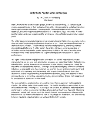
1) As electronics components shrink in size, the solder powder particles used in solder paste must also decrease to enable soldering of smaller interconnects. Solder powder particles are manufactured through an atomization process that involves melting alloy and dispersing it into tiny spherical droplets.
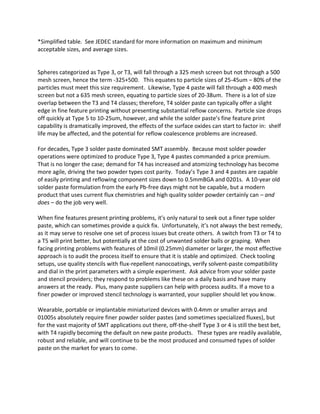
2) The size of solder powder particles is classified according to standard mesh screen sizes, ranging from Type 1 at 150-75 micrometers down to Type 7 at 11-2 micrometers. Type 3 and 4 particles between 25-45 micrometers and 20-38 micrometers respectively are most commonly used for mainstream surface mount applications.
3) While finer Type 5 powder between 10-25 micrometers may help with printing very small