Physics 505 Homework Reflection
•
1 like•172 views

This document provides solutions to homework problems from a physics course. It solves problems about the reflection and transmission of electromagnetic waves at the interface between two dielectric materials. When the incident angle is below the critical angle, the transmission and reflection coefficients exhibit interference behavior and oscillate as a function of the gap width. When above the critical angle, transmission decreases exponentially with gap width due to total internal reflection. Reflection from a conductor is also derived, showing the reflection coefficient approaches 1 at radio frequencies. Power conservation is demonstrated by relating the transmitted power to the imaginary part of the dielectric constant.

Recommended
More Related Content
What's hot
What's hot (19)
Viewers also liked
Viewers also liked (20)
Similar to Physics 505 Homework Reflection
Similar to Physics 505 Homework Reflection (20)
Recently uploaded
Recently uploaded (20)
Physics 505 Homework Reflection
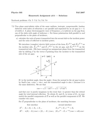
- 1. Physics 505 Fall 2007 Homework Assignment #11 — Solutions Textbook problems: Ch. 7: 7.3, 7.4, 7.6, 7.8 7.3 Two plane semi-infinite slabs of the same uniform, isotropic, nonpermeable, lossless dielectric with index of refraction n are parallel and separated by an air gap (n = 1) of width d. A plane electromagnetic wave of frequency ω is indicent on the gap from one of the slabs with angle of indicence i. For linear polarization both parallel to and perpendicular to the plane of incidence, a) calculate the ratio of power transmitted into the second slab to the incident power and the ratio of reflected to incident power; We introduce (complex) electric field vectors of the form Eieik·x and Ereik ·x on the incident side, E+eik0·x and E−eik0·x in the air gap, and Eteik·(x−d) on the transmitted side. (We have removed an unimportant phase from the transmitted side by shifting x by the vector d pointing from the incident to the transmitted side of the air gap). d k k’ k’0 k 0k i n nn=1 (air) r If i is the incident angle, then the angle r from the normal in the air gap is given by Snell’s law, n sin i = sin r, and the transmitted angle is also i (because it is the same dielectric). We see that cos r = 1 − sin2 r = 1 − n2 sin2 i and that cos r is purely imaginary in the event that i is greater than the critical angle for total internal reflection. To obtain Et and Er in terms of Ei, we may match the parallel components of E as well as the parallel components of H. We consider two cases. For E perpendicular to the plane of incidence, the matching becomes first interface second interface E : Ei + Er = E+ + E−, E+eiφ + E−e−iφ = Et H : n(Ei − Er) cos i = (E+ − E−) cos r, (E+eiφ − E−e−iφ ) cos r = nEt cos i
- 2. where we have introduced the phase φ = k0 · d = k0d cos r = ωd cos r c The matching conditions at the first interface may be written as E+ = 1 2 Ei(1 + α) + 1 2 Er(1 − α) E− = 1 2 Ei(1 − α) + 1 2 Er(1 + α) (1) where we have defined α = n cos i cos r = n cos i 1 − n2 sin2 i Similarly, the matching conditions at the second interface yield E+ = 1 2 e−iφ Et(1 + α) E− = 1 2 eiφ Et(1 − α) (2) Equating (1) and (2) allows us to solve for the ratios Et Ei = 4α (1 + α)2e−iφ − (1 − α)2eiφ = 2α 2α cos φ − i(1 + α2) sin φ Er Ei = (1 − α2 )(eiφ − e−iφ ) (1 + α)2e−iφ − (1 − α)2eiφ = i(1 − α2 ) sin φ 2α cos φ − i(1 + α2) sin φ (3) where α = n cos i 1 − n2 sin2 i , φ = ωd cos r c = ωd 1 − n2 sin2 i c So long as i is below the critical angle, both α and φ are real. In this case, the transmission and reflection coefficients are T = Et Ei 2 = 4α2 4α2 cos2 φ + (1 + α2)2 sin2 φ = 4α2 4α2 + (1 − α2)2 sin2 φ R = Er Ei 2 = (1 − α2 )2 sin2 φ 4α2 cos2 φ + (1 + α2)2 sin2 φ = (1 − α2 )2 sin2 φ 4α2 + (1 − α2)2 sin2 φ (4) Note that T + R = 1, as expected. However, this exhibits a classic interference behavior, where T oscillates between (2α/(1 + α2 ))2 and 1 as the number of wavelengths in the gap vary. For E parallel to the plane of incidence, we find instead the matching conditions first interface second interface E : (Ei − Er) cos i = (E+ − E−) cos r, (E+eiφ − E−e−iφ ) cos r = Et cos i H : n(Ei + Er) = (E+ + E−), E+eiφ − E−e−iφ = nEt
- 3. These equations have the same structure as the perpendicular case, but with the index of refraction entering somewhat differently. We find the matching conditions n−1 E+ = 1 2 Ei(1 + β) + 1 2 Er(1 − β) n−1 E− = 1 2 Ei(1 − β) + 1 2 Er(1 + β) and n−1 E+ = 1 2 e−iφ Et(1 + β) n−1 E− = 1 2 eiφ Et(1 − β) where this time β = cos i n cos r = cos i n 1 − n2 sin2 i These expressions are similar to (1) and (2) above, except with the replacement E± → n−1 E± and α → β. Hence the transmission and reflection coefficients are given by expressions identical to (4), except with the replacement α → β. b) for i greater than the critical angle for total internal reflection, sketch the ratio of transmitted power to incident power as a function of d measured in units of wavelength in the gap. To be concrete, consider the case for E perpendicular to the plane of incidence. Since i is greater than the critical angle, both α and φ will be purely imaginary. Whatever values they are, define α = iγ, φ = iξ Then the ratios Et/Ei and Er/Ei in (3) become Et Ei = 2iγ 2iγ cosh ξ + (1 − γ2) sinh ξ Er Ei = −(1 + γ2 ) sinh ξ 2iγ cosh ξ + (1 − γ2) sinh ξ so that T = Et Ei 2 = 4γ2 4γ2 + (1 + γ2)2 sinh2 ξ R = Er Ei 2 = (1 + γ2 )2 sinh2 ξ 4γ2 + (1 + γ2)2 sinh2 ξ where γ = − n cos i n2 sin2 i − 1 , ξ = ωd n2 sin2 i − 1 c In this case, there is no oscillatory behavior in the transmitted power, but only exponential suppression as the air gap is widened. It is easy to see that T → 1
- 4. when d → 0 (corresponding to ξ → 0) and that T falls exponentially to 0 when d → ∞ (which is the same as ξ → ∞). For n = 1.5 (approximately the index of refraction of glass), the critical angle for total internal reflection is i0 ≈ 42◦ . A sketch of T as a function of d looks like 0.5 1 1.5 2 0.2 0.4 0.6 0.8 1 T d/(2π / k0 ) =1.5n i =75 i =60 i =45 7.4 A plane-polarized electromagnetic wave of frequency ω in free space is incident nor- mally on the flat surface of a nonpermeable medium of conductivity σ and dielectric constant . a) Calculate the amplitude and phase of the reflected wave relative to the incident wave for arbitrary σ and . A medium of dielectric constant and conductivity σ may be described by an effective dielectric constant ε = + i σ ω Since the medium is nonpermeable, we have µ = µ0. As a result, for normal incidence, the ratio of the reflected to the incident electric field is Er Ei = 1 − n 1 + n where n = ε 0 = 0 + i σ 0ω The amplitude A and phase ϕ of the reflected wave is defined by Aeiϕ = Er Ei = 1 − / 0 + iσ/ 0ω 1 + / 0 + iσ/ 0ω This expression implicitly defines A and ϕ. To be more explicit, we decompose the complex index of refraction into a magnitude and phase n = √ ηeiα/2
- 5. where η = 0 2 + σ 0ω 2 , tan α = σ ω (5) The amplitude of the reflected wave is then A = (1 − n)(1 − n∗) (1 + n)(1 + n∗) = 1 + |n|2 − 2 n 1 + |n|2 + 2 n = 1 + η − 2 √ η cos(α/2) 1 + η + 2 √ η cos(α/2) (6) while the phase is ϕ = arg 1 − n 1 + n = arg (1 − n)(1 + n∗ ) (1 + n)(1 + n∗) = tan−1 −2 n 1 − |n|2 = tan−1 −2 √ η sin(α/2) 1 − η (7) Note that some care must be taken when extracting the phase. In particular, for ϕ = tan−1 (y/x), we must ensure that the angle ϕ lies in the proper quadrant defined by the point (x, y). This is why we choose to keep the minus sign in the numerator inside the arctan. Since the numerator is always negative, ϕ must lie in either the 3rd or the 4th quadrant. For η > 1, which is the case for all conventional dielectrics, ϕ lies in the 3rd quadrant. To highlight this, we may write ϕ = π + tan−1 2 √ η sin(α/2) η − 1 (8) b) Discuss the limiting cases of a very poor and a very good conductor, and show that for a good conductor the reflection coefficient (ratio of reflected to incident intensity) is approximately R ≈ 1 − 2 ω c δ where δ is the skin depth. We begin with the case of a very poor conductor, σ ω. In this case, η and α in (5) simplify to η ≈ 0 , α ≈ σ ω where we have kept only linear terms in σ. Substituting this into (6) and (8) gives A ≈ 1 − √ η 1 + √ η = 1 − ¯n 1 + ¯n ϕ ≈ π + √ η η − 1 σ ω = π + ¯n ¯n2 − 1 σ ω where ¯n = / 0. Here we have assumed that ¯n > 1 and that σ/ ω ¯n − 1. For a very good conductor, we take the opposite limit, σ ω. In this case η ≈ σ 0ω 1, α ≈ π 2
- 6. Inserting this into (6) and (8) gives A ≈ η − √ 2η + 1 η + √ 2η + 1 ≈ 1 − 2/η 1 + 2/η 1/2 ≈ 1 − 2 η = 1 − 2 0ω σ ϕ ≈ π + tan−1 √ 2η η − 1 ≈ π + tan−1 2 η ≈ π The amplitude A may be rewritten in terms of the skin depth δ = 2/µ0σω A ≈ 1 − ωδ √ µ0 0 = 1 − ω c δ This gives the reflection coefficient R = A2 ≈ 1 − 2 ω c δ (9) 7.6 A plane wave of frequency ω is incident normally from vacuum on a semi-infinite slab of material with a complex index of refraction n(ω) [n2 (ω) = (ω)/ 0]. a) Show that the ratio of reflected power to incident power is R = 1 − n(ω) 1 + n(ω) 2 while the ratio of power transmitted into the medium to the incident power is T = 4 n(ω) |1 + n(ω)|2 While this problem involves a complex dielectric constant (ω), we note that the matching conditions for incident and reflected waves at an interface hold for arbitrary (including complex) values of µ and . For normal incidence, the expressions are simply Er Ei = 1 − n(ω) 1 + n(ω) , Et Ei = 2 1 + n(ω) where we have furthermore assumed that the material is non-permeable so that µ = µ0. For harmonic waves, the power is obtained from the real part of the Poynting vector S = 1 2 E × H∗ = 1 2 ∗ µ∗ |E|2 ˆn (10)
- 7. The reflection coefficient is then straightforward R = (ˆn · Sr) (ˆn · Si) = Er Ei 2 = 1 − n(ω) 1 + n(ω) 2 For the transmission coefficient, we also have to account for the different material T = (ˆn · St) (ˆn · Si) = (ω)∗ 0 Et Ei 2 = 4 [n(ω)] |1 + n(ω)|2 b) Evaluate [iω(E · D∗ − B · H∗ )/2] as a function of (x, y, z). Show that this rate of change of energy per unit volume accounts for the relative transmitted power T. We write the electric and magnetic fields inside the material as E = Eteikˆn·x , B = √ µ0 0n(ω)ˆn × Eteikˆn·x where the complex wavenumber k is given by k(ω) = ωn(ω) c In this case, the power per unit volume expression becomes iω 2 (E · D∗ − B · H∗ ) = iω 2 (ω)∗ |E|2 − 1 µ0 |B|2 = iω 2 ( (ω)∗ − 0|n(ω)|2 )|Et|2 e−2 [k(ω)]ˆn·x = i 0ω 2 (n(ω)2 ∗ − |n(ω)|2 )|Et|2 e−2 [k(ω)]ˆn·x = 0ω [n(ω)2 ] 2 |Et|2 e−2 [k(ω)]ˆn·x = 0ω [n(ω)] [n(ω)]|Et|2 e−2 [k(ω)]ˆn·x = 0 µ0 [n(ω)] [k(ω)]|Et|2 e−2 [k(ω)]ˆn·x (11) The power per area transmitted into the material may then be calculated as Pt/A = ∞ 0 iω 2 (E · D∗ − B · H∗ ) dz = 0 µ0 [n(ω)] [k(ω)]|Et|2 ∞ 0 e−2 [k(ω)]z dz = 1 2 0 µ0 [n(ω)]|Et|2
- 8. On the other hand, the incident power per area may be obtained from (10) Pi/A = 1 2 0 µ0 |Ei|2 (12) This gives Pt Pi = [n(ω)] Et Ei 2 = [n(ω)] × 4 |1 + n(ω)|2 which agrees with the above calculation of the transmission coefficient. Note that the complex Poynting vector inside the material is S = 1 2 0 µ0 n(ω)∗ |Et|2 e−2 [k(ω)]ˆn·x ˆn Hence ( · S ) = − 0 µ0 [n(ω)] [k(ω)]|Et|2 e−2 [k(ω)]ˆn·x (13) Comparing this with (11) demonstrates that the real part of the complex Poynt- ing’s theorem holds · S + iω 2 (E · D∗ − B · H∗ ) + 1 2 J∗ · E = 0 so long as we take J = 0 (ie no free currents). c) For a conductor, with n2 = 1 + i(σ/ω 0), σ real, write out the results of parts a and b in the limit 0ω σ. Express your answer in terms of δ as much as possible. Calculate 1 2 (J∗ · E) and compare with the result of part b. Do both enter the complex form of Poynting’s theorem? For a conductor with σ ω 0, we make the approximation n = 1 + i σ ω 0 ≈ (1 + i) σ 2ω 0 = (1 + i) c ωδ where we have introduced the skin depth δ = 2/µ0σω. In this case, the reflec- tion coefficient is approximately R = 1 − n 1 + n 2 = 1 − n−1 1 + n−1 2 ≈ 1 − (1 − i)ωδ/2c 1 + (1 − i)ωδ/2c 2 ≈ 1 − (1 − i) ωδ c 2 ≈ 1 − 2(1 − i) ωδ c = 1 − 2 ωδ c + 2i ωδ c ≈ 1 − 2 ωδ c Not surprisingly, this is the same result as (9). The transmission coefficient is approximately T = 4 n |1 + n|2 ≈ 4c/ωδ |1 + (1 + i)c/ωδ|2 ≈ 4c/ωδ |(1 + i)c/ωδ|2 = 2ωδ c (14)
- 9. Note that R + T ≈ 1 as expected. For the power per unit volume of part b, we have from (11) iω 2 (E · D∗ − B · H∗ ) = 0ω (n) (n)|Et|2 e−2 (k)ˆn·ˆx ≈ 0ω c ωδ 2 |Et|2 e−2ˆn·x/δ = 0c2 ωδ2 |Et|2 e−2ˆn·x/δ Integrating this along z gives a power per area transmitted into the conductor Pt/A = ∞ 0 0c2 ωδ2 |Et|2 e−2z/δ dz = 0c2 2ωδ |Et|2 Comparing this with the incident power per area (12) gives Pt Pi = c ωδ Et Ei 2 = c ωδ 4 |1 + n|2 ≈ 4c ωδ 1 |n|2 ≈ 4c ωδ 1 |(1 + i)c/ωδ|2 = 2ωδ c which agrees with the transmission coefficient (14). For the divergence of the Poynting vector, note that (13) becomes ( · S) ≈ − 0c2 ωδ2 |Et|2 e−2ˆn·x/δ On the other hand, using J = σE, we see that [1 2 (J∗ · E)] = [1 2 σ|E|2 ] = 1 2 σ|Et|2 e−2 [k(ω)]ˆn·x = 0c2 ωδ2 |Et|2 e−2ˆn·x/δ This expression gives the same value as the power per unit volume term [iω(E · D∗ − B · H∗ )/2]. Hence if we include both the power per unit volume term and the work term [1 2 (J∗ · E)] in the complex Poynting’s theorem · S + iω 2 (E · D∗ − B · H∗ ) + 1 2 J∗ · E = 0 we would double count the contribution of the current, and this theorem would appear to be violated. To get the correct result, we recall that we have a choice of where the current J should be counted. In particular, by writing n2 = 1+i(σ/ω 0), we have played the trick of hiding the current J in the electric displacement D → Deff = D + i ω J = 0 + iσ ω E = eff E
- 10. In this case, the Amp`ere-Maxwell law becomes simply × H = −iωDeff In particular, once we assume Deff = eff E, we have set the explicit current to zero in this equation (although it is hidden in Deff ). In this case, the ‘correct’ complex Poynting’s theorem reads · S + iω 2 (E · D∗ eff − B · H∗ ) = 0 where the work term is hidden in the power per unit volume term. Since ex- pression (11) was actually calculated with Deff , this is the form of the Poynting’s theorem that we have directly shown for the conductor. On the other hand, if we treat the current J as an explicit quantity, then it enters through the work term [1 2 (J∗ ·E)], but does not enter the power per unit volume term. In this case, we return to the full Poynting’s theorem · S + iω 2 (E · D∗ − B · H∗ ) + 1 2 J∗ · E = 0 where D is the ‘honest’ electric displacement, without the addition of an effective current contribution. (For n2 = 1 + i(σ/ω 0), we have D = 0E). Using this expression for D modifies the calculation of (11). In particular iω 2 (E · D∗ − B · H∗ ) = iω 2 0|E|2 − 1 µ0 |B|2 = 0 since 0 and µ0 are both real. As a result, when treating J explicitly, power conservation is a balance between · S and 1 2 J∗ · E only. 7.8 A monochromatic plane wave of frequency ω is indicdent normally on a stack of layers of various thicknesses tj and lossless indices of refraction nj. Inside the stack, the wave has both forward and backward moving components. The change in the wave through any interface and also from one side of a layer to the other can be described by means of 2 × 2 transfer matrices. If the electric field is written as E = E+eikx + E−e−ikx in each layer, the transfer matrix equation E = TE is explicitly E+ E− = t11 t12 t21 t22 E+ E− a) Show that the transfer matrix for propagation inside, but across, a layer of index of refraction nj and thickness tj is Tlayer(nj, tj) = eikj tj 0 0 e−ikj tj = I cos(kjtj) + iσ3 sin(kjtj)
- 11. where kj = njω/c, I is the unit matrix, and σk are the Pauli spin matrices of quantum mechanics. Show that the inverse matrix is T∗ . Normal incidence makes this problem straightforward. For a right moving plane wave of the form eikj z passing through a layer of thickness tj, one picks up a phase eikj tj , while for a left moving wave, one picks up a phase e−ikj tj . More precisely E+ = E+(z = tj) = E+(z = 0)eikj tj = E+eikj tj E− = E−(z = tj) = E−(z = 0)e−ikj tj = E−e−ikj tj This directly leads to the transfer matrix Tlayer(nj, tj) = eikj tj 0 0 e−ikj tj where the inverse is obviously the complex conjugate. b) Show that the transfer matrix to cross an interface from n1 (x < x0) to n2 (x > x0) is Tinterface(2, 1) = 1 2 n + 1 −(n − 1) −(n − 1) n + 1 = I (n + 1) 2 − σ1 (n − 1) 2 where n = n1/n2. For the matching across layers, we take the E perpendicular to plane of incidence conventions. This gives simply E : E+ + E− = E+ + E− H : n1(E+ − E−) = n2(E+ − E−) which may be solved to give E+ = 1 2 E+(1 + n) + 1 2 E−(1 − n) E− = 1 2 E+(1 − n) + 1 2 E−(1 + n) where n = n1/n2. This yields the transfer matrix Tinterface(2, 1) = 1 2 n + 1 −(n − 1) −(n − 1) n + 1 c) Show that for a complete stack, the incident, reflected, and transmitted waves are related by Etrans = det(T) t22 Einc, Erefl = − t21 t22 Einc
- 12. where tij are the elements of T, the product of the forward-going transfer ma- trices, including from the material filling space on the incident side into the first layer and from the last layer into the medium filling the space on the transmitted side. It ought to be clear that the complete effect of going through several layers is to take a product of transfer matrices. For example E = TE, where T = · · · T(4, 3)T(n3, t3)T(3, 2)T(n2, t2)T(2, 1) The transmitted and reflected electric fields are obtained by solving Et 0 = T Ei Er = t11 t12 t21 t22 Ei Er This gives explicitly Et = t11Ei + t12Er, 0 = t21Ei + t22Er which may be solved to obtain Er = − t21 t22 Ei, Et = t11t22 − t12t21 t22 Ei = det(T) t22 Ei