Downloaded 129 times
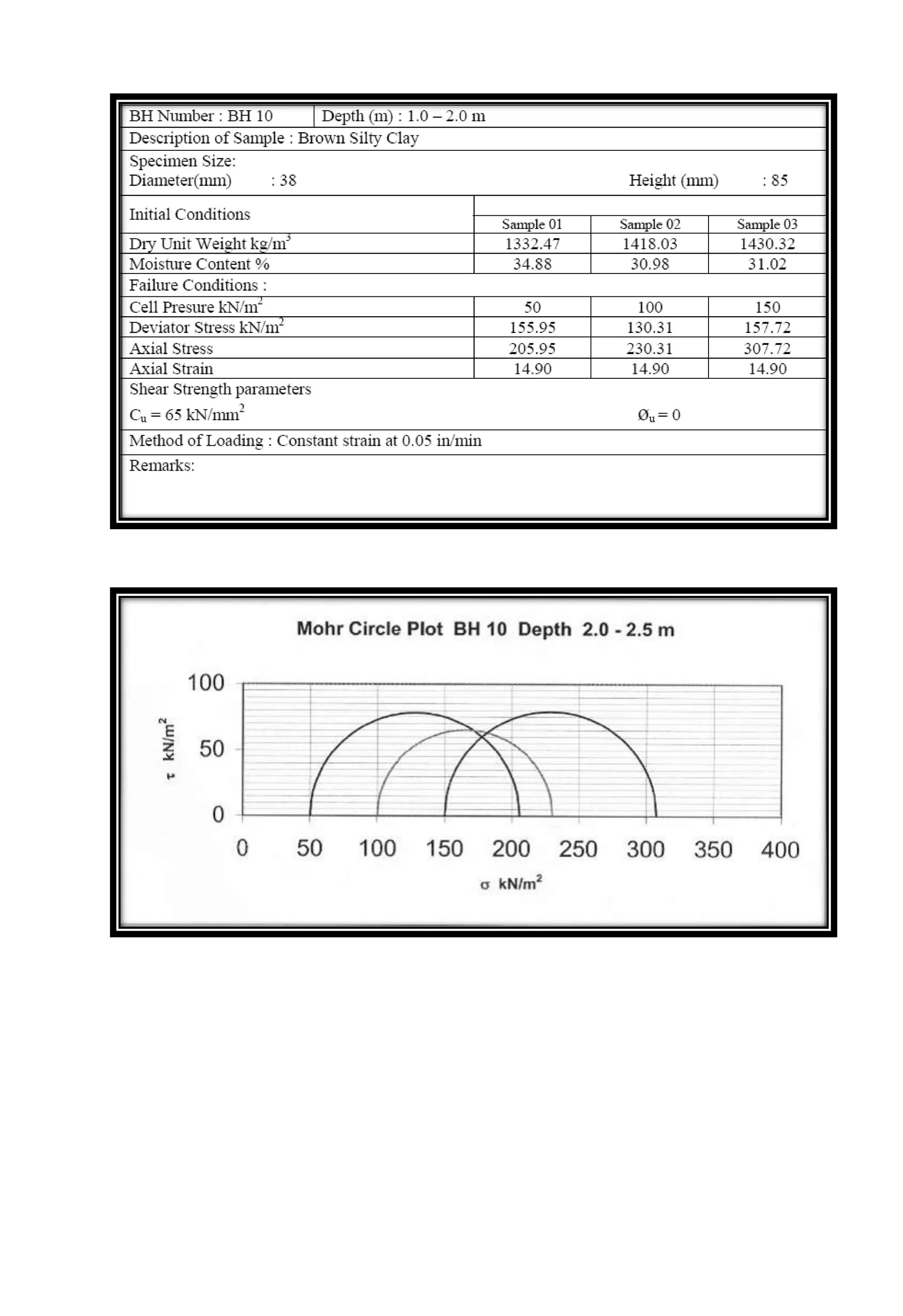
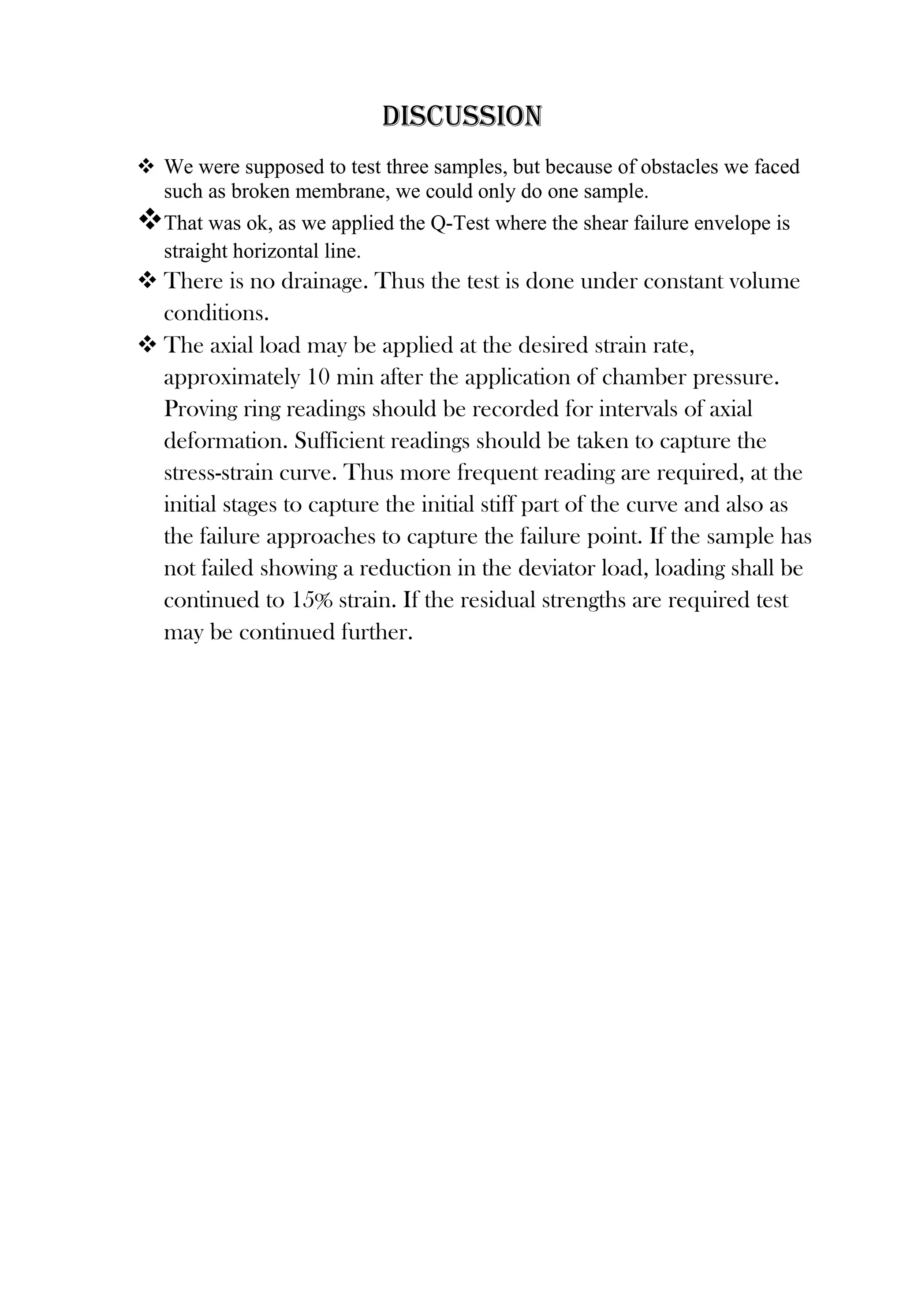

This document provides information on conducting triaxial tests to determine the shear strength parameters of cohesive soils. It describes the objectives, theory, equipment, procedures, data analysis, discussion, and conclusions for performing unconsolidated undrained triaxial tests. Specimens are cylindrical soil samples encased in a rubber membrane and subjected to confining pressure and axial loads in a triaxial chamber. Data collected includes applied loads and deformations which are used to calculate stresses and strains and develop the shear strength failure envelope from tests run at different confining pressures. Care must be taken in sample preparation and testing to minimize disturbances and ensure accurate, repeatable results.


![Vibe Coding vs. Spec-Driven Development [Free Meetup]](https://cdn.slidesharecdn.com/ss_thumbnails/vibecodingvsspecdrivendevelopment-251209105622-43f455e7-thumbnail.jpg?width=640&height=640&fit=bounds)


