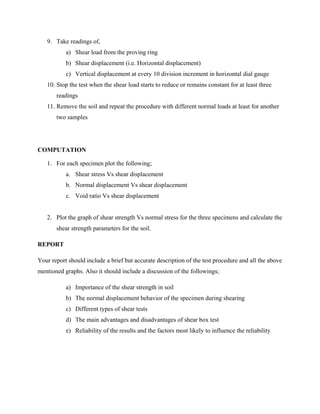
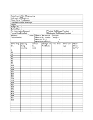
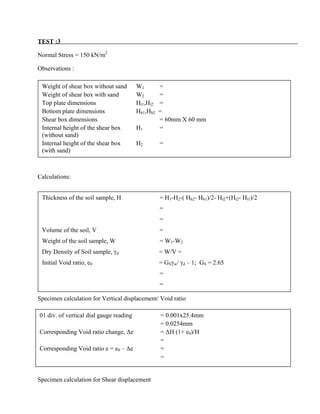
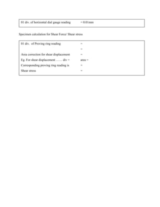
DIRECT SHEAR TEST
SOIL MECHANICS
SOIL MECHANICS LABORATORY
DEPARTMENT OF CIVIL
ENGINEERING
UNIVERSITY OF MORATUWA
SRI LANKA
DIRECT SHEAR TEST
OBJEVTIVES
To determine the shear strength parameters for a given soil using the direct shear test.
INTRODUCTION
The test is carried out on either undisturbed samples or remoulded samples. To facilitate the
remoulding purpose, a soil sample may be compacted at optimum moisture content in a
compaction mould. Then specimen for the direct shear test could be obtained using the correct
cutter provided. Alternatively, sand sample can be placed in a dry state at a required density, in
the assembled shear box.
A normal load is applied to the specimen and the specimen is sheared across the pre-determined
horizontal plane between the two halves of the shear box. Measurements of shear load, shear
displacement and normal displacement are recorded. The test is repeated foe two or more
identical specimens under different normal loads. From the results, the shear strength parameters
can be determined.
THEORY
The strength of a soil depends of its resistance to shearing stresses. It is made up of basically the
components;
1. Frictional – due to friction between individual particles.
2. Cohesive - due to adhesion between the soil particles
The two components are combined in Colulomb’s shear strength equation,
τf = c + σf tan ø
Where τf = shearing resistance of soil at failure
c = apparent cohesion of soil
σf = total normal stress on failure plane
ø = angle of shearing resistance of soil (angle of internal friction)
This equation can also be written in terms of effective stresses.
PROCEDURE
1. Assemble the shear box
2. Compact the soil sample in mould after bringing it to optimum moisture condition
3. Carefully transfer the sample into shear box
τf = c’ + σ’f tan ø’
Where c’ = apparent cohesion of soil in terms of effective stresses
σ'f = effective normal stress on failure plane
ø’ = angle of shearing resistance of soil in terms of effective stresses
σ'f = σf - uf
uf = pore water pressure on failure plane
4. Place the loading plate on top of the upper porous plate. After recording the weight of the
loading carrier place it is on the loading cap.
5. Position all dial gauges and set the readings to zero. Remove the alignment screws which
hold two halves of the shear box together
6. Tighten the remaining, two diagonally opposite screws, until there is a small gap between
upper and lower boxes to reduce the frictional force
7. Apply the desired normal load. If there is any vertical displacement, wait till the dial
gauges indicate a constant reading and then reset the dial gauge to zero
8. Check that screws have been removed and then start the motor to produce the desired
constant rate of shearing
9. Take readings of,
a) Shear load from the proving ring
b) Shear displacement (i.e. Horizontal displacement)
c) Vertical displacement at every 10 division increment in horizontal dial gauge
10. Stop the test when the shear load starts to reduce or remains constant for at least three
readings
11. Remove the soil and repeat the procedure with different normal loads at least for another
two samples
COMPUTATION
1. For each specimen plot the following;
a. Shear stress Vs shear displacement
b. Normal displacement Vs shear displacement
c. Void ratio Vs shear displacement
2. Plot the graph of shear strength Vs normal stress for the three specimens and calculate the
shear strength parameters for the soil.
REPORT
Your report should include a brief but accurate description of the test procedure and all the above
mentioned graphs. Also it should include a discussion of the followings;
a) Importance of the shear strength in soil
b) The normal displacement behavior of the specimen during shearing
c) Different types of shear tests
d) The main advantages and disadvantages of shear box test
e) Reliability of the results and the factors most likely to influence the reliability
Department of Civil Engineering
University of Moratuwa
Direct Shear Test Results
Load Deformation Readings
Project :
Sample No. :
Type of Test :
Proving reading Constant =
Normal Load Applied =
Vertical Dial Gauge Constant :
Horizontal Dial Gauge Constant :
Moisture Content
Determination
Mass of Wet sample + Can (g) =
Mass of Dry sample + Can (g) =
Mass of Can (g) =
Moisture Content (%) =
Shear Disp.
div.
Proving
Ring
reading
Vertical
Dis.
(mm)
Change in
Void Ratio
Void Ratio Shear force
(kg)
Shear
Stress
(kN/m2
)
0
10
20
30
40
50
75
100
125
150
175
200
225
250
275
300
325
350
375
400
425
450
475
500
TEST :3
Normal Stress = 150 kN/m2
Observations :
Calculations:
Specimen calculation for Vertical displacement/ Void ratio
Specimen calculation for Shear displacement
Weight of shear box without sand W1 =
Weight of shear box with sand W2 =
Top plate dimensions Ht1,Ht2 =
Bottom plate dimensions Hb1,Hb2 =
Shear box dimensions = 60mm X 60 mm
Internal height of the shear box H1 =
(without sand)
Internal height of the shear box H2 =
(with sand)
Thickness of the soil sample, H = H1-H2-( Hb2- Hb1)/2- Ht2+(Ht2- Ht1)/2
=
=
Volume of the soil, V =
Weight of the soil sample, W = W1-W2
Dry Density of Soil sample, γd = W/V =
Initial Void ratio, e0 = GSγw/ γd – 1; GS = 2.65
=
=
01 div. of vertical dial gauge reading = 0.001x25.4mm
= 0.0254mm
Corresponding Void ratio change, ∆e = ∆H (1+ e0)/H
=
Corresponding Void ratio e = e0 – ∆e =
=
Specimen calculation for Shear Force/ Shear stress
01 div. of horizontal dial gauge reading = 0.01mm
01 div. of Proving ring reading =
=
Area correction for shear displacement =
Eg. For shear displacement …… div = area =
Corresponding proving ring reading is =
Shear stress =
TEST :1
Normal Stress = 50 kN/mm2
Observations :
Calculations:
Specimen calculation for Vertical displacement/ Void ratio
Specimen calculation for Shear displacement
Weight of shear box without sand W1 = 2.665
Weight of shear box with sand W2 = 2.910
Top plate dimensions Ht1,Ht2 = 1.70mm, 3.44mm
Bottom plate dimensions Hb1,Hb2 = 1.74mm, 3.26mm
Shear box dimensions = 60mm X 60 mm
Internal height of the shear box H1 = 43.60 mm
(without sand)
Internal height of the shear box H2 = 0mm
(with sand)
Thickness of the soil sample, H = H1-H2-( Hb2- Hb1)/2- Ht2+(Ht2- Ht1)/2
= 43.60-(3.26-1.74)/2-3.44+(3.44-1.70)/2
= 40.27mm
Volume of the soil, V = 60x60x40.27 mm3
= 1.45x10⁻⁴
m3
Weight of the soil sample, W = W1-W2
= 2.910-2.665 kg = 0.245 kg
Dry Density of Soil sample, γd = W/V = 0.245 /1.45x10-4
kg/ m3
Initial Void ratio, e0 = GSγw/ γd – 1; GS = 2.65
= 2.65x10³
/1689.66 - 1
= 0.568
01 div. of vertical dial gauge reading = 0.001x25.4mm
= 0.0254mm
Corresponding Void ratio change, ∆e = ∆H (1+ e0)/H
= 0.0254(1+0.568)/40.27
= 0.989x10⁻³
Corresponding Void ratio e = e0 – ∆e = 0.568 - 0.989x10-3
= 0.567
Specimen calculation for Shear Force/ Shear stress
01 div. of horizontal dial gauge reading = 0.01mm
01 div. of Proving ring reading = 0.6lbs
= 0.6/2.206 kg
= 0.272 kg
Area correction for shear displacement
Eg. For shear displacement 200 div = 2mm area = 60 x (60-2) = 3480 mm2
Corresponding proving ring reading is = 6 div = 6 x 0.272 kg = 1.632 kg
Shear stress = 1.632/3480 kg/mm2
= 4.60 kN/ m2
Department of Civil Engineering
University of Moratuwa
Direct Shear Test Results
Load Deformation Readings
Project :
Sample No. :
Type of Test :
Proving reading Constant = 0.6lbs/div.
Normal Load Applied = 18.34 kg (50 kN/m2
)
Vertical Dial Gauge Constant = 0.001”
Horizontal Dial Gauge Constant = 0.01mm
Moisture Content Determination Mass of Wet sample + Can (g) =
Mass of Dry sample + Can (g) =
Mass of Can (g) =
Moisture Content (%) =
Shear
Disp.
div.
Proving
Ring
reading
Vertical
Gauge
Reading
Vertical
Dis.
(mm)
Change in
Void
Ratio
Void
Ratio
Shear
force
(kg)
Shear
Stress
(kN/m2
)
0 0 0 0 0.00000 0.56800 0.00000 0
10 1 -0.5 -0.0127 -0.00049 0.56849 0.27199 0.756777
20 2 -1 -0.0254 -0.00099 0.56899 0.54397 1.516084
30 2.5 -2 -0.0508 -0.00198 0.56998 0.67996 1.89828
40 3 -2 -0.0508 -0.00198 0.56998 0.81596 2.281758
50 3.5 -2 -0.0508 -0.00198 0.56998 0.95195 2.666524
75 4 -2.5 -0.0635 -0.00247 0.57047 1.08794 3.060315
100 4.5 -3.5 -0.0889 -0.00346 0.57146 1.22393 3.457443
125 5 -4.5 -0.1143 -0.00445 0.57245 1.35993 3.85795
150 5.5 -5.5 -0.1397 -0.00544 0.57344 1.49592 4.261881
175 6 -6.5 -0.1651 -0.00643 0.57443 1.63191 4.669279
200 6 -7.5 -0.1905 -0.00742 0.57542 1.63191 4.689405
225 6 -8.5 -0.2159 -0.00841 0.57641 1.63191 4.709706
250 6 -9.5 -0.2413 -0.00940 0.57740 1.63191 4.730183
275 6 -10.5 -0.2667 -0.01038 0.57838 1.63191 4.750838
300 6 -11.5 -0.2921 -0.01137 0.57937 1.63191 4.771675
325 6 -12 -0.3048 -0.01187 0.57987 1.63191 4.792696
350 6 -12 -0.3048 -0.01187 0.57987 1.63191 4.813903
375 6 -12 -0.3048 -0.01187 0.57987 1.63191 4.835298
400 6 -12 -0.3048 -0.01187 0.57987 1.63191 4.856884
425
450
475
500
direct_shear_test.pdf

direct_shear_test.pdf

  • 1.
    DIRECT SHEAR TEST SOILMECHANICS SOIL MECHANICS LABORATORY DEPARTMENT OF CIVIL ENGINEERING UNIVERSITY OF MORATUWA SRI LANKA
  • 2.
    DIRECT SHEAR TEST OBJEVTIVES Todetermine the shear strength parameters for a given soil using the direct shear test. INTRODUCTION The test is carried out on either undisturbed samples or remoulded samples. To facilitate the remoulding purpose, a soil sample may be compacted at optimum moisture content in a compaction mould. Then specimen for the direct shear test could be obtained using the correct cutter provided. Alternatively, sand sample can be placed in a dry state at a required density, in the assembled shear box. A normal load is applied to the specimen and the specimen is sheared across the pre-determined horizontal plane between the two halves of the shear box. Measurements of shear load, shear displacement and normal displacement are recorded. The test is repeated foe two or more identical specimens under different normal loads. From the results, the shear strength parameters can be determined. THEORY The strength of a soil depends of its resistance to shearing stresses. It is made up of basically the components; 1. Frictional – due to friction between individual particles. 2. Cohesive - due to adhesion between the soil particles The two components are combined in Colulomb’s shear strength equation, τf = c + σf tan ø Where τf = shearing resistance of soil at failure c = apparent cohesion of soil σf = total normal stress on failure plane ø = angle of shearing resistance of soil (angle of internal friction) This equation can also be written in terms of effective stresses.
  • 3.
    PROCEDURE 1. Assemble theshear box 2. Compact the soil sample in mould after bringing it to optimum moisture condition 3. Carefully transfer the sample into shear box τf = c’ + σ’f tan ø’ Where c’ = apparent cohesion of soil in terms of effective stresses σ'f = effective normal stress on failure plane ø’ = angle of shearing resistance of soil in terms of effective stresses σ'f = σf - uf uf = pore water pressure on failure plane
  • 4.
    4. Place theloading plate on top of the upper porous plate. After recording the weight of the loading carrier place it is on the loading cap. 5. Position all dial gauges and set the readings to zero. Remove the alignment screws which hold two halves of the shear box together 6. Tighten the remaining, two diagonally opposite screws, until there is a small gap between upper and lower boxes to reduce the frictional force 7. Apply the desired normal load. If there is any vertical displacement, wait till the dial gauges indicate a constant reading and then reset the dial gauge to zero 8. Check that screws have been removed and then start the motor to produce the desired constant rate of shearing
  • 5.
    9. Take readingsof, a) Shear load from the proving ring b) Shear displacement (i.e. Horizontal displacement) c) Vertical displacement at every 10 division increment in horizontal dial gauge 10. Stop the test when the shear load starts to reduce or remains constant for at least three readings 11. Remove the soil and repeat the procedure with different normal loads at least for another two samples COMPUTATION 1. For each specimen plot the following; a. Shear stress Vs shear displacement b. Normal displacement Vs shear displacement c. Void ratio Vs shear displacement 2. Plot the graph of shear strength Vs normal stress for the three specimens and calculate the shear strength parameters for the soil. REPORT Your report should include a brief but accurate description of the test procedure and all the above mentioned graphs. Also it should include a discussion of the followings; a) Importance of the shear strength in soil b) The normal displacement behavior of the specimen during shearing c) Different types of shear tests d) The main advantages and disadvantages of shear box test e) Reliability of the results and the factors most likely to influence the reliability
  • 6.
    Department of CivilEngineering University of Moratuwa Direct Shear Test Results Load Deformation Readings Project : Sample No. : Type of Test : Proving reading Constant = Normal Load Applied = Vertical Dial Gauge Constant : Horizontal Dial Gauge Constant : Moisture Content Determination Mass of Wet sample + Can (g) = Mass of Dry sample + Can (g) = Mass of Can (g) = Moisture Content (%) = Shear Disp. div. Proving Ring reading Vertical Dis. (mm) Change in Void Ratio Void Ratio Shear force (kg) Shear Stress (kN/m2 ) 0 10 20 30 40 50 75 100 125 150 175 200 225 250 275 300 325 350 375 400 425 450 475 500
  • 7.
    TEST :3 Normal Stress= 150 kN/m2 Observations : Calculations: Specimen calculation for Vertical displacement/ Void ratio Specimen calculation for Shear displacement Weight of shear box without sand W1 = Weight of shear box with sand W2 = Top plate dimensions Ht1,Ht2 = Bottom plate dimensions Hb1,Hb2 = Shear box dimensions = 60mm X 60 mm Internal height of the shear box H1 = (without sand) Internal height of the shear box H2 = (with sand) Thickness of the soil sample, H = H1-H2-( Hb2- Hb1)/2- Ht2+(Ht2- Ht1)/2 = = Volume of the soil, V = Weight of the soil sample, W = W1-W2 Dry Density of Soil sample, γd = W/V = Initial Void ratio, e0 = GSγw/ γd – 1; GS = 2.65 = = 01 div. of vertical dial gauge reading = 0.001x25.4mm = 0.0254mm Corresponding Void ratio change, ∆e = ∆H (1+ e0)/H = Corresponding Void ratio e = e0 – ∆e = =
  • 8.
    Specimen calculation forShear Force/ Shear stress 01 div. of horizontal dial gauge reading = 0.01mm 01 div. of Proving ring reading = = Area correction for shear displacement = Eg. For shear displacement …… div = area = Corresponding proving ring reading is = Shear stress =
  • 9.
    TEST :1 Normal Stress= 50 kN/mm2 Observations : Calculations: Specimen calculation for Vertical displacement/ Void ratio Specimen calculation for Shear displacement Weight of shear box without sand W1 = 2.665 Weight of shear box with sand W2 = 2.910 Top plate dimensions Ht1,Ht2 = 1.70mm, 3.44mm Bottom plate dimensions Hb1,Hb2 = 1.74mm, 3.26mm Shear box dimensions = 60mm X 60 mm Internal height of the shear box H1 = 43.60 mm (without sand) Internal height of the shear box H2 = 0mm (with sand) Thickness of the soil sample, H = H1-H2-( Hb2- Hb1)/2- Ht2+(Ht2- Ht1)/2 = 43.60-(3.26-1.74)/2-3.44+(3.44-1.70)/2 = 40.27mm Volume of the soil, V = 60x60x40.27 mm3 = 1.45x10⁻⁴ m3 Weight of the soil sample, W = W1-W2 = 2.910-2.665 kg = 0.245 kg Dry Density of Soil sample, γd = W/V = 0.245 /1.45x10-4 kg/ m3 Initial Void ratio, e0 = GSγw/ γd – 1; GS = 2.65 = 2.65x10³ /1689.66 - 1 = 0.568 01 div. of vertical dial gauge reading = 0.001x25.4mm = 0.0254mm Corresponding Void ratio change, ∆e = ∆H (1+ e0)/H = 0.0254(1+0.568)/40.27 = 0.989x10⁻³ Corresponding Void ratio e = e0 – ∆e = 0.568 - 0.989x10-3 = 0.567
  • 10.
    Specimen calculation forShear Force/ Shear stress 01 div. of horizontal dial gauge reading = 0.01mm 01 div. of Proving ring reading = 0.6lbs = 0.6/2.206 kg = 0.272 kg Area correction for shear displacement Eg. For shear displacement 200 div = 2mm area = 60 x (60-2) = 3480 mm2 Corresponding proving ring reading is = 6 div = 6 x 0.272 kg = 1.632 kg Shear stress = 1.632/3480 kg/mm2 = 4.60 kN/ m2
  • 11.
    Department of CivilEngineering University of Moratuwa Direct Shear Test Results Load Deformation Readings Project : Sample No. : Type of Test : Proving reading Constant = 0.6lbs/div. Normal Load Applied = 18.34 kg (50 kN/m2 ) Vertical Dial Gauge Constant = 0.001” Horizontal Dial Gauge Constant = 0.01mm Moisture Content Determination Mass of Wet sample + Can (g) = Mass of Dry sample + Can (g) = Mass of Can (g) = Moisture Content (%) = Shear Disp. div. Proving Ring reading Vertical Gauge Reading Vertical Dis. (mm) Change in Void Ratio Void Ratio Shear force (kg) Shear Stress (kN/m2 ) 0 0 0 0 0.00000 0.56800 0.00000 0 10 1 -0.5 -0.0127 -0.00049 0.56849 0.27199 0.756777 20 2 -1 -0.0254 -0.00099 0.56899 0.54397 1.516084 30 2.5 -2 -0.0508 -0.00198 0.56998 0.67996 1.89828 40 3 -2 -0.0508 -0.00198 0.56998 0.81596 2.281758 50 3.5 -2 -0.0508 -0.00198 0.56998 0.95195 2.666524 75 4 -2.5 -0.0635 -0.00247 0.57047 1.08794 3.060315 100 4.5 -3.5 -0.0889 -0.00346 0.57146 1.22393 3.457443 125 5 -4.5 -0.1143 -0.00445 0.57245 1.35993 3.85795 150 5.5 -5.5 -0.1397 -0.00544 0.57344 1.49592 4.261881 175 6 -6.5 -0.1651 -0.00643 0.57443 1.63191 4.669279 200 6 -7.5 -0.1905 -0.00742 0.57542 1.63191 4.689405 225 6 -8.5 -0.2159 -0.00841 0.57641 1.63191 4.709706 250 6 -9.5 -0.2413 -0.00940 0.57740 1.63191 4.730183 275 6 -10.5 -0.2667 -0.01038 0.57838 1.63191 4.750838 300 6 -11.5 -0.2921 -0.01137 0.57937 1.63191 4.771675 325 6 -12 -0.3048 -0.01187 0.57987 1.63191 4.792696 350 6 -12 -0.3048 -0.01187 0.57987 1.63191 4.813903 375 6 -12 -0.3048 -0.01187 0.57987 1.63191 4.835298 400 6 -12 -0.3048 -0.01187 0.57987 1.63191 4.856884 425 450 475 500