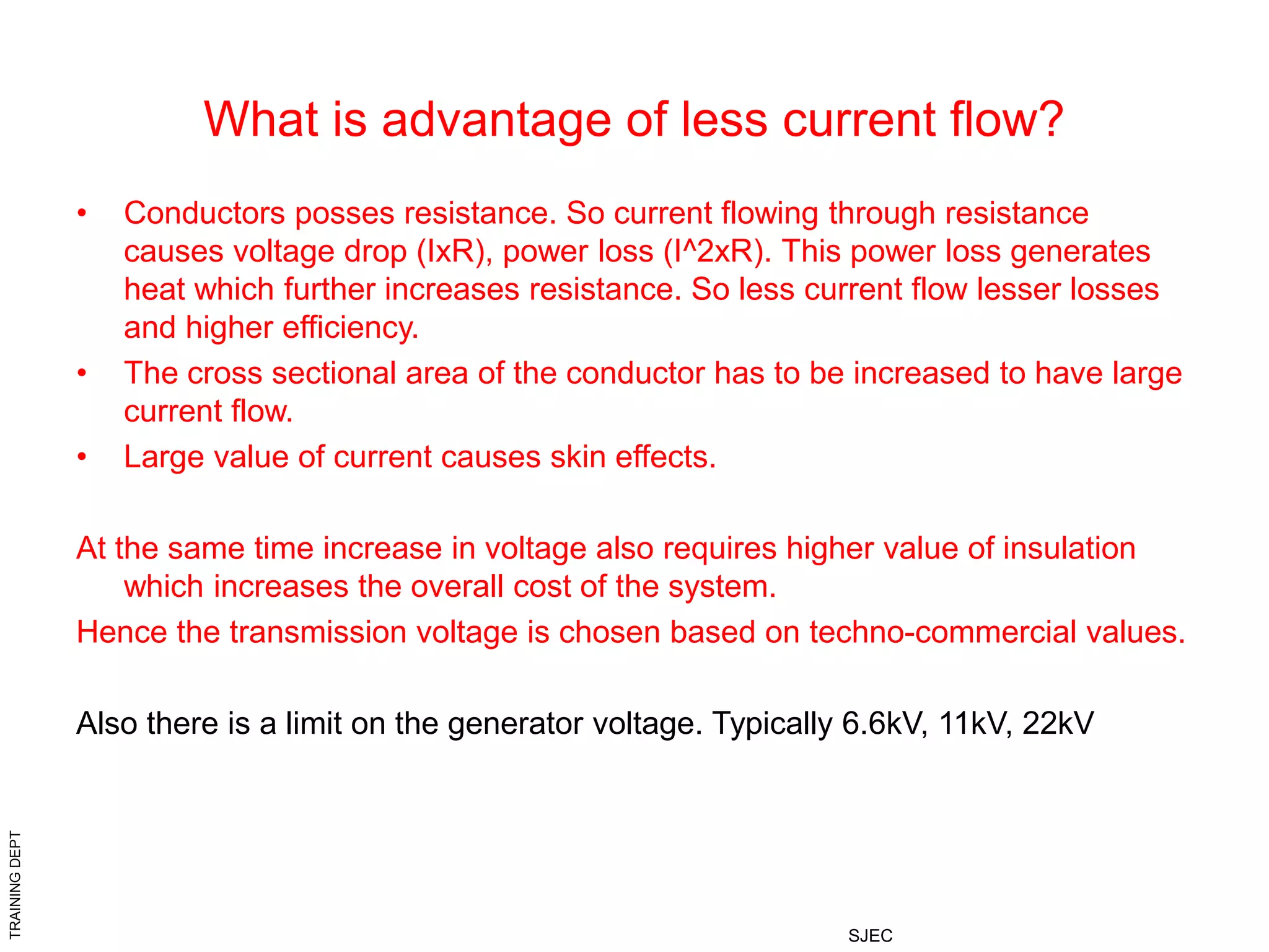
TRAINING
DEPT
SJEC
TRANSFORMER
PROTECTION
2 Winding
Auto transformer
Earthing transformer
Reactor
TRAINING
DEPT
SJEC
Why transformer is needed?
• Take a task of transmitting a power of
1000W.
Power = Voltage x Current W
Required current at various voltages to transmit 1000W is given below
(I=P/V A)
If voltage = 10V current = 100A
voltage = 100V current = 10A
voltage = 1000V current = 1A
TRAINING
DEPT
SJEC
What is advantage of less current flow?
• Conductors posses resistance. So current flowing through resistance
causes voltage drop (IxR), power loss (I^2xR). This power loss generates
heat which further increases resistance. So less current flow lesser losses
and higher efficiency.
• The cross sectional area of the conductor has to be increased to have large
current flow.
• Large value of current causes skin effects.
At the same time increase in voltage also requires higher value of insulation
which increases the overall cost of the system.
Hence the transmission voltage is chosen based on techno-commercial values.
Also there is a limit on the generator voltage. Typically 6.6kV, 11kV, 22kV
TRAINING
DEPT
SJEC
Need of Transformer
• In order to raise the voltage at the
beginning of transmission line (generating
stations) and to lower it to various levels in
sub-transmission, distribution & utilization
levels a transformer is required.
TRAINING
DEPT
SJEC
Transformer Characteristics
• Input power is equal to output power. (Neglecting losses)
• The raising or lowering of voltage is accompanied with
corresponding lowering or raising of current.
• There is no change in frequency.
• Output waveform is an exact replica of Input waveform.
(Except during inrush and saturation)
TRAINING
DEPT
SJEC
Basic Construction
• Basically a transformer consists of two
windings on a magnetic core. The winding
to which power is given is called Primary
Winding. The winding from which
transformed power is taken out is called
Secondary winding.
TRAINING
DEPT
SJEC
Principle of Operation
• When a sinusoidal voltage is applied across a winding (1), a
sinusoidal current flows through it.
• This sinusoidal current flowing through winding (1) (Coil of many
turns) sets up a sinusoidal magnetic field.
(Basic principle: When a current flows through a conductor, a
magnetic field is setup)
• Nearly entire portion of this sinusoidal magnetic field flows through
the magnetic core.
(Magnetic core offers more easy path than air for flow of magnetic
field)
• This magnetic field links with the another winding(2) placed on the
core.
TRAINING
DEPT
SJEC
Continued
• This magnetic field linking with the another coil being sinusoidal in
nature induces an emf in the another winding(2).
• So the basic principle for transformer operation is continuously
changing flux in magnetic core. An emf is induced only when there is
change of flux. Sinusoidal wave (current) continuously changes and
hence produces continuous changing flux.
• A Steady DC voltage/current (no change in value) cannot produce
changing flux and hence a transformer cannot work on steady DC.
TRAINING
DEPT
SJEC
Formulae used in Transformer
problems
• Transformation Ratio :
( N1 / N2 ) = ( V1 / V2 ) = ( I2 / I1 )
where 1 indicates primary winding &
2 indicates secondary winging.
• Input power = Output power (losses neglected)
V1I1 cos ø = V2I2 cos ø
Transformer doesn’t have its own power factor (Neglecting no load
current). Its power factor is the same as that of the load. Hence
rating of the transformer is specified in VA (KVA, MVA etc) [Apparent
power] and not in watts W (kW, MW etc) [Real power].
As already stated transformer doesn’t introduce any change in
frequency or waveform.
TRAINING
DEPT
SJEC
Voltage Regulation
• Broadly explained it is the ratio of voltage deviation to expected
voltage.
% Regulation = Expected voltage – Actual Voltage x 100
Expected voltage
So, we have to implement some mechanism to have constant
voltage at the secondary [customer] even though there is
fluctuations in the primary side [supplier].
This is done in transformers directly changing the turns ratio suitably
to meet the situation. Usually turns ratio is changed in the HV side
since HV winding has lesser current. [As this is a moving
mechanism and its is always advantageous to deal with smaller
current].
TRAINING
DEPT
SJEC
Continued
This mechanism is called as TAP CHANGER. Tap changers are
classified into two types based on the load conditions of operation
a. ON LOAD tap changers
b. OFF LOAD tap changers
ON LOAD tap changers are the one capable of changing turns
ratio without any interruptions in service. [Basically it is motor
operated] e.g. Transformer used in transmission network.
OFF LOAD tap changers are mostly manually operated and
possible to operate only when the transformer is de-energized.
e.g. Transformers used in distribution network
TRAINING
DEPT
SJEC
0
1
4
5
2
3
6
9
8
7
10
TAP CHANGERS
PRIMARY VOLTAGE
TRAINING
DEPT
SJEC
As already stated in previous slides a
TAP changer is mostly placed in the
HV side of the transformer. The main
aim is to maintain the LV voltage at a
constant voltage (within certain limits).
This has to take care of both over
voltage and under voltage conditions.
All tap changers have a tap called
NOMINAL tap. This tap is designed for
the rated voltage of the transformer.
Transformer windings are provided with no.
tapings in HV side based on the required
voltage range. Usually this may be -20% to
+10%. These are nothing but connections
taken out from winding at different no. of
turns to suite the requirement.
TRAINING
DEPT
SJEC
For e.g.. The requirement is to have a 1000 / 100 V transformer. The HV
winding is to be designed for -14% to +4% in steps of 2%.
(-14%, -12%, -10%, -8%, -6%, -4%, -2%, 0%, 2%, 4% Total 10 taps)
(860V, 880V, 900V, 920V, 940V, 960V, 980V, 1000V, 1020V, 1040V)
Let us assume the HV winding to be Primary and LV to be Secondary.
The secondary voltage must remain at 100V even when there is a
fluctuation in primary voltage from 860V to 1040 volts. Now the let us
assume there is 200 turns in LV winding. (Based on design calculations).
This gives 200turns/100V = 2 turns per volt.
Since the HV max voltage is 1040V it must have 1040V x 2 turns per volt =
2080 turns
The tapings are to placed at
860 x 2 = 1720 turns 880 x 2 = 1760 turns 900 x 2 = 1800 turns
920 x 2 = 1840 turns 940 x 2 = 1880 turns 960 x 2 = 1920 turns
980 x 2 = 1960 turns 1000 x 2 = 2000 turns 1020 x 2 = 2040 turns
1040 x 2 = 2080 turns
Tapings will be placed all these turns. 2000 turns is the nominal turns for the
HV winding and LV winding will have 200 turns with no tapings.
TRAINING
DEPT
SJEC
Voltage Turns Tap no. Transformation ratio
860 V 1720 turns 1 8.6
880 V 1760 turns 2 8.8
900 V 1800 turns 3 9.0
920 V 1840 turns 4 9.2
940 V 1880 turns 5 9.4
960 V 1920 turns 6 9.6
980 V 1960 turns 7 9.8
1000V 2000 turns 8 10.0 (Nominal TAP)
1020V 2040 turns 9 10.2
1040V 2080 turns 10. 10.4
When the primary voltage is 1000V, the tap changer will connect tap 8
to the primary voltage and thereby secondary voltage is 100V.
Transformation ratio is 10.0.
Now when the primary is 960V the but we need to get 100V. So the
transformer must have a transformation ratio of 9.6. To get this, the tap
changer connects TAP 6 to the primary voltage and now the secondary
voltage is again 100V.
TRAINING
DEPT
SJEC
AUTO-TRANSFORMERS
• Auto transformers have only one winding [for single
phase]. Same winding acts as HV and LV. The VARIAC
we used in our college electrical laboratory is an Auto-
transformer.
• The operation principle is the same as that of two
winding transformer described before is previous slides.
• The only difference between two winding transformer
and auto-transformer is usage of lesser copper wire due
to LV winding forming part of HV winding. Especially
when the transformation is nearing unity auto-
transformer gives great saving in copper.
TRAINING
DEPT
SJEC
continued
• The disadvantage of auto-transformer is, it doesn’t provide electrical
isolation between HV & LV circuits which we get in two winding
transformers.
TRAINING
DEPT
SJEC
TRANSFORMER LOADING
This refers to electrical loading and not to loading & unloading
during transportation and erecting process.
• Say, the Primary (HV/LV) winding is energized with the rated
voltage. (Here onwards rated voltage means voltage of correct magnitude, frequency &
sinusoidal without harmonics unless specified explicitly) It induces a self induced emf
in the primary winding whose direction is opposite to the applied
voltage. Numerically its value is nearly equal to that of the applied
voltage. (since the windings are highly inductive due to magnetic core)
• An emf is induced in the secondary (LV/HV) winding (mutually
induced emf), which appears as voltage at the secondary winding
terminals. Since the transformer is not loaded, current through
secondary winding is ZERO.
• But primary winding carries some current which is utilized for
magnetizing the core due to which emf is induced in the secondary
winding. This current in primary winding is nearly 90o lagging since
windings are highly inductive circuits.
TRAINING
DEPT
SJEC
continued
• If the resistance of the primary winding is neglected, there is no
power involved in magnetizing the core of transformer.
Power = V x I x Cos ø since ø = 90o Cos ø = 0
= 0 watt.
So transformer on ZERO Load [Secondary open circuited] draws ZERO
power. (neglecting losses which is usually very very small.)
• Now when a load is connected to the secondary winding, a currents
start to flow in the secondary winding and creates a magnetic field.
TRAINING
DEPT
SJEC
continued
• The direction of the current flowing in the secondary
winding is opposite to the current flowing in the primary
winding when checked at identical terminals of the two
windings. (The procedure for finding identical terminals of both the
windings is explained latter under heading “POLARITY TEST”.)
• The current being in opposite direction, the magnetic field is also in
opposite direction. The effect of this secondary winding magnetic
field is to reduce the net magnetic field in the core. (Since direction
is opposite, algebraically it has –ve sign. Just for understanding).
• When the net magnetic field in the core reduces, it results in
reduction of the self induced emf (Logically, opposing force for applied voltage) in
the primary winding.
• This increases difference between applied voltage and self induced
emf in the primary winding and thereby current increases in the
primary winding to restore the original magnetic flux in the core.
TRAINING
DEPT
SJEC
continued
• When the secondary load is further increased the above process
repeats and increases the primary current in proportional to
transformation ratio.
Basically the winding of the transformer is classified as HV & LV by
the manufacturer, and it is the user who decides which is Primary
and secondary. The winding to which we give power (HV/LV) is
called Primary winding and the winding from which we take power
(LV/HV) is called Secondary winding.
TRAINING
DEPT
SJEC
Identifying terminals & Vector
Groups
• First consider the case of single phase transformers.
Usually one of the primary winding terminal & one of the secondary
winding terminal will have some kind of identical marking indicating
them as identical terminals.
Note down the diagram below. It has 4 terminals, two for primary &
two for secondary. Primary winding is marked as 1U & 1V whereas
TRAINING
DEPT
SJEC
Continued…..
Secondary terminals are marked 2u & 2v. A dot is placed at 1U & 2u. This
dot has some significance. It indicates the direction (polarity) of winding
(voltage) w.r.t other terminal ie when 1U is +ve wrt 1V then 2u is +ve wrt 2v.
This indicates that when 1V & 2v are made as reference for their respective
windings and the phase angle between primary (1U1V) & secondary
(2u2v) voltage measured will give 0 deg phase shift.
Now if 1V & 2u are made as reference for their respective windings and the
phase angle between primary (1U1V) & secondary (2v2u) voltage
measured will give 180 deg phase shift.
Therefore the above two condition may be considered as 12 o clock & 6 o
clock vector group. However this vector has no meaning since it is decided
only by external connections. A single phase transformer can be made as
12 o clock or 6 o clock without any difficulty.
TRAINING
DEPT
SJEC
Continued…
This is not the case with 3 phase transformers.
Now let us examine the importance of this 12 o clock & 6 o clock
vector group in single phase transformers. The significance of vector
group lies when there is a need to connect transformers in parallel.
Refer the ckt below.
TRAINING
DEPT
SJEC
Continued….
In the above ckt the identical terminals of two different transformers
are connected together. (via corresponding bus bar) This presents
no problem in parallel operation. Now consider below ckt.
TRAINING
DEPT
SJEC
Continued….
In this case, transformer 2 is having 6 o clock vector group, whereas
transformer 1 is having 12 o clock vector group. When these two
transformers are connected parallel in above manner it is worse
than a dead short and there will be enormous short circuit current
limited only by winding resistance & bus bar resistance which is very
very less.
TRAINING
DEPT
SJEC
VECTOR GROUP
VECTOR group of transformers and its significance
The waveform of secondary winding is a true replica of primary
winding waveform (provided there is continuous change in the
waveform and there is no saturation in core).
The Amplitude & RMS value of the waveform change based on the
transformation ratio. The frequency is not changed. But the two
waveforms may or may not be in phase with each other. There is a
phase angle difference between the two waveforms and this phase
angle remains constant until the vector group is undisturbed.
This phase angle difference plays significance when trying to
operate transformers in parallel, as these phase angle difference
results in local circulating currents as we saw with some examples
in previous slides.
While defining VECTOR groups the HV winding phasor is taken as
reference. Mostly 12 o clock is mentioned as 0 o clock.
TRAINING
DEPT
SJEC
PHASE VOLTAGE / LINE VOLTAGE
.
This is the voltage phasor of 3
phase balanced system.
VR, VY, VB are three phase voltages.
VR-Y, VY-B, VB-R three LINE voltages.
Vectorial subtraction is obtained by
R-Y = R+(-Y) ie reverse the vector
to be subtracted and add it to the
vector from which it is to be
subtracted.
It is seen from the vector diagram
that
VR-Y leads VR by 30o,
VY-B leads VY by 30o and
VB-R leads VB by 30o.
Therefore VL=√3VPh and VL leads VPh by 30o (In a star connected winding)
This the relation between phase voltage and line voltage.
TRAINING
DEPT
SJEC
LINE & PHASE VOLTAGE RELATIONSHIP IN 3 PHASE
CONNECTION
STAR CONNECTION
The line voltage leads phase voltage by 30
degrees in STAR connected winding.
VL=√3VPh
The line current and phase current are in
phase and equal in magnitude. IL= IPh
DELTA CONNECTION
The line voltage and phase voltage are in
phase and equal in magnitude in DELTA
connection
The line current lags phase current by 30
TRAINING
DEPT
SJEC
VECTOR GROUPS IN STAR CONNECTED WINDINGS
For all purpose of theory and calculation a 3 phase transformer may
considered as a 3 single phase transformers connected as per
requirement.
Consider a 3 phase transformer with both primary and secondary
winding connected in STAR connection.
When we say STAR connection all similar ends (either starting or
ending ends and not a mixture) of a particular winding are
connected together.
CORRECT CONNECTION INCORRECT CONNECTION
TRAINING
DEPT
SJEC
Yy0
.
Applying the same concept of single phase transformer vector group, when R phase
HV is +ve, R phase LV is also positive. The same logic applies for all other 2 phases.
This connection is a 12 o clock vector group (zero degree phase shift also 0 o clock).
This is more explained by phasor diagram shown above. It seen from the phasor
diagram there is no phase difference between respective vectors. Hence this is a 12
o clock connection.
Here point in both windings are formed by shorting finishing ends in both HV & LV
sides. Similar vector group may also be formed by shorting starting ends of both HV
& LV windings.
HV SIDE PHASOR LV SIDE PHASOR
HV SIDE
LV SIDE
TRAINING
DEPT
SJEC
Yy6
.
Applying the same concept of single phase transformer vector group, when R phase HV is +ve,
R phase LV is -ve. The same logic applies for all other 2 phases. This connection is a 6 o clock
vector group (180 degree phase shift). This is more explained by phasor diagram shown above.
It seen from the phasor diagram there is a phase difference of 180 degrees between respective
vectors. Hence this is a 6 o clock connection.
Here the star point in HV winding is formed by shorting finishing ends and star point of LV
winding is formed by shorting starting ends. Hence we get the phase shift of 180 degrees in
secondary winding only.
Similar vector group may also be formed by shifting the star point in both HV & LV windings. For
simplicity only one is shown here.
HV SIDE PHASOR
LV SIDE PHASOR
HV SIDE
LV SIDE
TRAINING
DEPT
SJEC
VECTOR GROUPS IN DELTA CONNECTED WINDINGS
For all purpose of theory and calculation a 3 phase transformer may
considered as a 3 single phase transformers connected as per
requirement.
Consider a 3 phase transformer with both primary and secondary
winding connected in DELTA connection.
When we say DELTA connection all dis-similar ends (starting end of
one winding is connected to finishing end of other winding and
similar ends are never connected together) of different ends are
connected together.
CORRECT CONNECTION INCORRECT CONNECTION
TRAINING
DEPT
SJEC
HV SIDE PHASOR LV SIDE PHASOR
HV SIDE
LV SIDE
Applying the same concept of single phase transformer vector group, when R phase HV is +ve,
R phase LV is also positive. The same logic applies for all other 2 phases. This connection is a
12 o clock vector group (zero degree phase shift. Also 0 o clock)
This is more explained by phasor diagram shown above. It seen from the phasor diagram there
is no phase difference between respective vectors. Hence this is a 12 o clock connection.
Here in HV side starting end of R is connected to finishing end of B, starting end of Y is
connected to finishing end of R and starting end of B is connected to finishing end of Y.
Similarly in LV side starting end of R is connected to finishing end of B, starting end of Y is
connected to finishing end of R and starting end of B is connected to finishing end of Y.
Dd0
TRAINING
DEPT
SJEC
HV SIDE PHASOR LV SIDE PHASOR
HV SIDE
LV SIDE
Applying the same concept of single phase transformer vector group, when R phase HV is +ve, R phase LV is
also positive. The same logic applies for all other 2 phases. This connection is a 6 o clock vector group (zero
degree phase
shift. This is more explained by phasor diagram shown above. It seen from the phasor diagram there is a 180
degree phase difference between respective vectors. Hence this is a 6 o clock connection.
Here in HV side starting end of R is connected to finishing end of B, starting end of Y is connected to finishing
end of R and starting end of B is connected to finishing end of Y.
Similarly in LV side starting end of R is connected to finishing end of B, starting end of Y is connected to
finishing end of R and starting end of B is connected to finishing end of Y.
But the difference is made in taking out the external LV leads which is opposite to that of previous case. This
gives 180 degrees phase shift.
Dd6
TRAINING
DEPT
SJEC
VECTOR GROUPS IN STRAR - DELTA CONNECTED
WINDINGS
HV SIDE
HV SIDE PHASOR
LV SIDE PHASOR
LV SIDE
This is an eg of 1 o clock connection. Just rotate both HV phasors
and LV phasor by 30 degree clockwise and view R phase line
voltages in both the cases. This forms the two hands of a clock forming
1 o clock. I hope the diagram itself is clear and needs no further
explanation
Yd1
TRAINING
DEPT
SJEC
Continued…
LV SIDE PHASOR
This is an eg of 11 o clock connection. Just view R phase line
voltages in both the cases. This forms the two hands of a clock forming
11 o clock. I hope the diagram itself is clear self explanatory and needs
no further explanation
HV SIDE
LV SIDE
HV SIDE PHASOR
Dy11
TRAINING
DEPT
SJEC
continued
HV SIDE
HV SIDE PHASOR
LV SIDE PHASOR
LV SIDE
This is an eg of 7 o clock connection. Just rotate both HV phasors
and LV phasor by 30 degree clockwise and view R phase line
voltages in both the cases. This forms the two hands of a clock forming
7 o clock. I hope the diagram itself is clear and needs no further
explanation
Yd7
TRAINING
DEPT
SJEC
This is an e.g. of 5 o clock connection. Just view R phase line
voltages in both the cases. This forms the two hands of a clock forming
5 o clock. I hope the diagram itself is clear self explanatory and needs
no further explanation
HV SIDE
LV SIDE
HV SIDE PHASOR LV SIDE PHASOR
Dy5
TRAINING
DEPT
SJEC
QUESTIONS - 2
1.I need each of you to send minimum 5 transformer name plate details
in any form (photograph, scanned copies, hand drawn etc) but actual
transformer data complete in all respects (including mechanical weight,
dimensions etc).
Those who have not send their replies to QUESTIONS-1, kindly send it
immediately as I have to consolidate the results and send it to HQ.
If I didn’t receive before next week, I will mark NO RESPONSE and will
be submitted to HQ.
Answers to QUESTIONS-1 will be published along with QUESTIONS-3
next week.
Best wishes.
TRAINING
DEPT
SJEC
QUESTIONS-1
.
TRAINING
DEPT
SJEC
QUESTIONS
• Any doubts on previous slides feel free to
get it clarified. All further presentations
depends upon previous slides.
• Now we have nearly finished basics. Next
week we will enter into transformers
Protection.
• Please provide your comments on clarity
of information.

TRANSFORMER PROTECTION.ppt

  • 1.
  • 2.
    TRAINING DEPT SJEC Why transformer isneeded? • Take a task of transmitting a power of 1000W. Power = Voltage x Current W Required current at various voltages to transmit 1000W is given below (I=P/V A) If voltage = 10V current = 100A voltage = 100V current = 10A voltage = 1000V current = 1A
  • 3.
    TRAINING DEPT SJEC What is advantageof less current flow? • Conductors posses resistance. So current flowing through resistance causes voltage drop (IxR), power loss (I^2xR). This power loss generates heat which further increases resistance. So less current flow lesser losses and higher efficiency. • The cross sectional area of the conductor has to be increased to have large current flow. • Large value of current causes skin effects. At the same time increase in voltage also requires higher value of insulation which increases the overall cost of the system. Hence the transmission voltage is chosen based on techno-commercial values. Also there is a limit on the generator voltage. Typically 6.6kV, 11kV, 22kV
  • 4.
    TRAINING DEPT SJEC Need of Transformer •In order to raise the voltage at the beginning of transmission line (generating stations) and to lower it to various levels in sub-transmission, distribution & utilization levels a transformer is required.
  • 5.
    TRAINING DEPT SJEC Transformer Characteristics • Inputpower is equal to output power. (Neglecting losses) • The raising or lowering of voltage is accompanied with corresponding lowering or raising of current. • There is no change in frequency. • Output waveform is an exact replica of Input waveform. (Except during inrush and saturation)
  • 6.
    TRAINING DEPT SJEC Basic Construction • Basicallya transformer consists of two windings on a magnetic core. The winding to which power is given is called Primary Winding. The winding from which transformed power is taken out is called Secondary winding.
  • 7.
    TRAINING DEPT SJEC Principle of Operation •When a sinusoidal voltage is applied across a winding (1), a sinusoidal current flows through it. • This sinusoidal current flowing through winding (1) (Coil of many turns) sets up a sinusoidal magnetic field. (Basic principle: When a current flows through a conductor, a magnetic field is setup) • Nearly entire portion of this sinusoidal magnetic field flows through the magnetic core. (Magnetic core offers more easy path than air for flow of magnetic field) • This magnetic field links with the another winding(2) placed on the core.
  • 8.
    TRAINING DEPT SJEC Continued • This magneticfield linking with the another coil being sinusoidal in nature induces an emf in the another winding(2). • So the basic principle for transformer operation is continuously changing flux in magnetic core. An emf is induced only when there is change of flux. Sinusoidal wave (current) continuously changes and hence produces continuous changing flux. • A Steady DC voltage/current (no change in value) cannot produce changing flux and hence a transformer cannot work on steady DC.
  • 9.
    TRAINING DEPT SJEC Formulae used inTransformer problems • Transformation Ratio : ( N1 / N2 ) = ( V1 / V2 ) = ( I2 / I1 ) where 1 indicates primary winding & 2 indicates secondary winging. • Input power = Output power (losses neglected) V1I1 cos ø = V2I2 cos ø Transformer doesn’t have its own power factor (Neglecting no load current). Its power factor is the same as that of the load. Hence rating of the transformer is specified in VA (KVA, MVA etc) [Apparent power] and not in watts W (kW, MW etc) [Real power]. As already stated transformer doesn’t introduce any change in frequency or waveform.
  • 10.
    TRAINING DEPT SJEC Voltage Regulation • Broadlyexplained it is the ratio of voltage deviation to expected voltage. % Regulation = Expected voltage – Actual Voltage x 100 Expected voltage So, we have to implement some mechanism to have constant voltage at the secondary [customer] even though there is fluctuations in the primary side [supplier]. This is done in transformers directly changing the turns ratio suitably to meet the situation. Usually turns ratio is changed in the HV side since HV winding has lesser current. [As this is a moving mechanism and its is always advantageous to deal with smaller current].
  • 11.
    TRAINING DEPT SJEC Continued This mechanism iscalled as TAP CHANGER. Tap changers are classified into two types based on the load conditions of operation a. ON LOAD tap changers b. OFF LOAD tap changers ON LOAD tap changers are the one capable of changing turns ratio without any interruptions in service. [Basically it is motor operated] e.g. Transformer used in transmission network. OFF LOAD tap changers are mostly manually operated and possible to operate only when the transformer is de-energized. e.g. Transformers used in distribution network
  • 12.
  • 13.
    TRAINING DEPT SJEC As already statedin previous slides a TAP changer is mostly placed in the HV side of the transformer. The main aim is to maintain the LV voltage at a constant voltage (within certain limits). This has to take care of both over voltage and under voltage conditions. All tap changers have a tap called NOMINAL tap. This tap is designed for the rated voltage of the transformer. Transformer windings are provided with no. tapings in HV side based on the required voltage range. Usually this may be -20% to +10%. These are nothing but connections taken out from winding at different no. of turns to suite the requirement.
  • 14.
    TRAINING DEPT SJEC For e.g.. Therequirement is to have a 1000 / 100 V transformer. The HV winding is to be designed for -14% to +4% in steps of 2%. (-14%, -12%, -10%, -8%, -6%, -4%, -2%, 0%, 2%, 4% Total 10 taps) (860V, 880V, 900V, 920V, 940V, 960V, 980V, 1000V, 1020V, 1040V) Let us assume the HV winding to be Primary and LV to be Secondary. The secondary voltage must remain at 100V even when there is a fluctuation in primary voltage from 860V to 1040 volts. Now the let us assume there is 200 turns in LV winding. (Based on design calculations). This gives 200turns/100V = 2 turns per volt. Since the HV max voltage is 1040V it must have 1040V x 2 turns per volt = 2080 turns The tapings are to placed at 860 x 2 = 1720 turns 880 x 2 = 1760 turns 900 x 2 = 1800 turns 920 x 2 = 1840 turns 940 x 2 = 1880 turns 960 x 2 = 1920 turns 980 x 2 = 1960 turns 1000 x 2 = 2000 turns 1020 x 2 = 2040 turns 1040 x 2 = 2080 turns Tapings will be placed all these turns. 2000 turns is the nominal turns for the HV winding and LV winding will have 200 turns with no tapings.
  • 15.
    TRAINING DEPT SJEC Voltage Turns Tapno. Transformation ratio 860 V 1720 turns 1 8.6 880 V 1760 turns 2 8.8 900 V 1800 turns 3 9.0 920 V 1840 turns 4 9.2 940 V 1880 turns 5 9.4 960 V 1920 turns 6 9.6 980 V 1960 turns 7 9.8 1000V 2000 turns 8 10.0 (Nominal TAP) 1020V 2040 turns 9 10.2 1040V 2080 turns 10. 10.4 When the primary voltage is 1000V, the tap changer will connect tap 8 to the primary voltage and thereby secondary voltage is 100V. Transformation ratio is 10.0. Now when the primary is 960V the but we need to get 100V. So the transformer must have a transformation ratio of 9.6. To get this, the tap changer connects TAP 6 to the primary voltage and now the secondary voltage is again 100V.
  • 16.
    TRAINING DEPT SJEC AUTO-TRANSFORMERS • Auto transformershave only one winding [for single phase]. Same winding acts as HV and LV. The VARIAC we used in our college electrical laboratory is an Auto- transformer. • The operation principle is the same as that of two winding transformer described before is previous slides. • The only difference between two winding transformer and auto-transformer is usage of lesser copper wire due to LV winding forming part of HV winding. Especially when the transformation is nearing unity auto- transformer gives great saving in copper.
  • 17.
    TRAINING DEPT SJEC continued • The disadvantageof auto-transformer is, it doesn’t provide electrical isolation between HV & LV circuits which we get in two winding transformers.
  • 18.
    TRAINING DEPT SJEC TRANSFORMER LOADING This refersto electrical loading and not to loading & unloading during transportation and erecting process. • Say, the Primary (HV/LV) winding is energized with the rated voltage. (Here onwards rated voltage means voltage of correct magnitude, frequency & sinusoidal without harmonics unless specified explicitly) It induces a self induced emf in the primary winding whose direction is opposite to the applied voltage. Numerically its value is nearly equal to that of the applied voltage. (since the windings are highly inductive due to magnetic core) • An emf is induced in the secondary (LV/HV) winding (mutually induced emf), which appears as voltage at the secondary winding terminals. Since the transformer is not loaded, current through secondary winding is ZERO. • But primary winding carries some current which is utilized for magnetizing the core due to which emf is induced in the secondary winding. This current in primary winding is nearly 90o lagging since windings are highly inductive circuits.
  • 19.
    TRAINING DEPT SJEC continued • If theresistance of the primary winding is neglected, there is no power involved in magnetizing the core of transformer. Power = V x I x Cos ø since ø = 90o Cos ø = 0 = 0 watt. So transformer on ZERO Load [Secondary open circuited] draws ZERO power. (neglecting losses which is usually very very small.) • Now when a load is connected to the secondary winding, a currents start to flow in the secondary winding and creates a magnetic field.
  • 20.
    TRAINING DEPT SJEC continued • The directionof the current flowing in the secondary winding is opposite to the current flowing in the primary winding when checked at identical terminals of the two windings. (The procedure for finding identical terminals of both the windings is explained latter under heading “POLARITY TEST”.) • The current being in opposite direction, the magnetic field is also in opposite direction. The effect of this secondary winding magnetic field is to reduce the net magnetic field in the core. (Since direction is opposite, algebraically it has –ve sign. Just for understanding). • When the net magnetic field in the core reduces, it results in reduction of the self induced emf (Logically, opposing force for applied voltage) in the primary winding. • This increases difference between applied voltage and self induced emf in the primary winding and thereby current increases in the primary winding to restore the original magnetic flux in the core.
  • 21.
    TRAINING DEPT SJEC continued • When thesecondary load is further increased the above process repeats and increases the primary current in proportional to transformation ratio. Basically the winding of the transformer is classified as HV & LV by the manufacturer, and it is the user who decides which is Primary and secondary. The winding to which we give power (HV/LV) is called Primary winding and the winding from which we take power (LV/HV) is called Secondary winding.
  • 22.
    TRAINING DEPT SJEC Identifying terminals &Vector Groups • First consider the case of single phase transformers. Usually one of the primary winding terminal & one of the secondary winding terminal will have some kind of identical marking indicating them as identical terminals. Note down the diagram below. It has 4 terminals, two for primary & two for secondary. Primary winding is marked as 1U & 1V whereas
  • 23.
    TRAINING DEPT SJEC Continued….. Secondary terminals aremarked 2u & 2v. A dot is placed at 1U & 2u. This dot has some significance. It indicates the direction (polarity) of winding (voltage) w.r.t other terminal ie when 1U is +ve wrt 1V then 2u is +ve wrt 2v. This indicates that when 1V & 2v are made as reference for their respective windings and the phase angle between primary (1U1V) & secondary (2u2v) voltage measured will give 0 deg phase shift. Now if 1V & 2u are made as reference for their respective windings and the phase angle between primary (1U1V) & secondary (2v2u) voltage measured will give 180 deg phase shift. Therefore the above two condition may be considered as 12 o clock & 6 o clock vector group. However this vector has no meaning since it is decided only by external connections. A single phase transformer can be made as 12 o clock or 6 o clock without any difficulty.
  • 24.
    TRAINING DEPT SJEC Continued… This is notthe case with 3 phase transformers. Now let us examine the importance of this 12 o clock & 6 o clock vector group in single phase transformers. The significance of vector group lies when there is a need to connect transformers in parallel. Refer the ckt below.
  • 25.
    TRAINING DEPT SJEC Continued…. In the aboveckt the identical terminals of two different transformers are connected together. (via corresponding bus bar) This presents no problem in parallel operation. Now consider below ckt.
  • 26.
    TRAINING DEPT SJEC Continued…. In this case,transformer 2 is having 6 o clock vector group, whereas transformer 1 is having 12 o clock vector group. When these two transformers are connected parallel in above manner it is worse than a dead short and there will be enormous short circuit current limited only by winding resistance & bus bar resistance which is very very less.
  • 27.
    TRAINING DEPT SJEC VECTOR GROUP VECTOR groupof transformers and its significance The waveform of secondary winding is a true replica of primary winding waveform (provided there is continuous change in the waveform and there is no saturation in core). The Amplitude & RMS value of the waveform change based on the transformation ratio. The frequency is not changed. But the two waveforms may or may not be in phase with each other. There is a phase angle difference between the two waveforms and this phase angle remains constant until the vector group is undisturbed. This phase angle difference plays significance when trying to operate transformers in parallel, as these phase angle difference results in local circulating currents as we saw with some examples in previous slides. While defining VECTOR groups the HV winding phasor is taken as reference. Mostly 12 o clock is mentioned as 0 o clock.
  • 28.
    TRAINING DEPT SJEC PHASE VOLTAGE /LINE VOLTAGE . This is the voltage phasor of 3 phase balanced system. VR, VY, VB are three phase voltages. VR-Y, VY-B, VB-R three LINE voltages. Vectorial subtraction is obtained by R-Y = R+(-Y) ie reverse the vector to be subtracted and add it to the vector from which it is to be subtracted. It is seen from the vector diagram that VR-Y leads VR by 30o, VY-B leads VY by 30o and VB-R leads VB by 30o. Therefore VL=√3VPh and VL leads VPh by 30o (In a star connected winding) This the relation between phase voltage and line voltage.
  • 29.
    TRAINING DEPT SJEC LINE & PHASEVOLTAGE RELATIONSHIP IN 3 PHASE CONNECTION STAR CONNECTION The line voltage leads phase voltage by 30 degrees in STAR connected winding. VL=√3VPh The line current and phase current are in phase and equal in magnitude. IL= IPh DELTA CONNECTION The line voltage and phase voltage are in phase and equal in magnitude in DELTA connection The line current lags phase current by 30
  • 30.
    TRAINING DEPT SJEC VECTOR GROUPS INSTAR CONNECTED WINDINGS For all purpose of theory and calculation a 3 phase transformer may considered as a 3 single phase transformers connected as per requirement. Consider a 3 phase transformer with both primary and secondary winding connected in STAR connection. When we say STAR connection all similar ends (either starting or ending ends and not a mixture) of a particular winding are connected together. CORRECT CONNECTION INCORRECT CONNECTION
  • 31.
    TRAINING DEPT SJEC Yy0 . Applying the sameconcept of single phase transformer vector group, when R phase HV is +ve, R phase LV is also positive. The same logic applies for all other 2 phases. This connection is a 12 o clock vector group (zero degree phase shift also 0 o clock). This is more explained by phasor diagram shown above. It seen from the phasor diagram there is no phase difference between respective vectors. Hence this is a 12 o clock connection. Here point in both windings are formed by shorting finishing ends in both HV & LV sides. Similar vector group may also be formed by shorting starting ends of both HV & LV windings. HV SIDE PHASOR LV SIDE PHASOR HV SIDE LV SIDE
  • 32.
    TRAINING DEPT SJEC Yy6 . Applying the sameconcept of single phase transformer vector group, when R phase HV is +ve, R phase LV is -ve. The same logic applies for all other 2 phases. This connection is a 6 o clock vector group (180 degree phase shift). This is more explained by phasor diagram shown above. It seen from the phasor diagram there is a phase difference of 180 degrees between respective vectors. Hence this is a 6 o clock connection. Here the star point in HV winding is formed by shorting finishing ends and star point of LV winding is formed by shorting starting ends. Hence we get the phase shift of 180 degrees in secondary winding only. Similar vector group may also be formed by shifting the star point in both HV & LV windings. For simplicity only one is shown here. HV SIDE PHASOR LV SIDE PHASOR HV SIDE LV SIDE
  • 33.
    TRAINING DEPT SJEC VECTOR GROUPS INDELTA CONNECTED WINDINGS For all purpose of theory and calculation a 3 phase transformer may considered as a 3 single phase transformers connected as per requirement. Consider a 3 phase transformer with both primary and secondary winding connected in DELTA connection. When we say DELTA connection all dis-similar ends (starting end of one winding is connected to finishing end of other winding and similar ends are never connected together) of different ends are connected together. CORRECT CONNECTION INCORRECT CONNECTION
  • 34.
    TRAINING DEPT SJEC HV SIDE PHASORLV SIDE PHASOR HV SIDE LV SIDE Applying the same concept of single phase transformer vector group, when R phase HV is +ve, R phase LV is also positive. The same logic applies for all other 2 phases. This connection is a 12 o clock vector group (zero degree phase shift. Also 0 o clock) This is more explained by phasor diagram shown above. It seen from the phasor diagram there is no phase difference between respective vectors. Hence this is a 12 o clock connection. Here in HV side starting end of R is connected to finishing end of B, starting end of Y is connected to finishing end of R and starting end of B is connected to finishing end of Y. Similarly in LV side starting end of R is connected to finishing end of B, starting end of Y is connected to finishing end of R and starting end of B is connected to finishing end of Y. Dd0
  • 35.
    TRAINING DEPT SJEC HV SIDE PHASORLV SIDE PHASOR HV SIDE LV SIDE Applying the same concept of single phase transformer vector group, when R phase HV is +ve, R phase LV is also positive. The same logic applies for all other 2 phases. This connection is a 6 o clock vector group (zero degree phase shift. This is more explained by phasor diagram shown above. It seen from the phasor diagram there is a 180 degree phase difference between respective vectors. Hence this is a 6 o clock connection. Here in HV side starting end of R is connected to finishing end of B, starting end of Y is connected to finishing end of R and starting end of B is connected to finishing end of Y. Similarly in LV side starting end of R is connected to finishing end of B, starting end of Y is connected to finishing end of R and starting end of B is connected to finishing end of Y. But the difference is made in taking out the external LV leads which is opposite to that of previous case. This gives 180 degrees phase shift. Dd6
  • 36.
    TRAINING DEPT SJEC VECTOR GROUPS INSTRAR - DELTA CONNECTED WINDINGS HV SIDE HV SIDE PHASOR LV SIDE PHASOR LV SIDE This is an eg of 1 o clock connection. Just rotate both HV phasors and LV phasor by 30 degree clockwise and view R phase line voltages in both the cases. This forms the two hands of a clock forming 1 o clock. I hope the diagram itself is clear and needs no further explanation Yd1
  • 37.
    TRAINING DEPT SJEC Continued… LV SIDE PHASOR Thisis an eg of 11 o clock connection. Just view R phase line voltages in both the cases. This forms the two hands of a clock forming 11 o clock. I hope the diagram itself is clear self explanatory and needs no further explanation HV SIDE LV SIDE HV SIDE PHASOR Dy11
  • 38.
    TRAINING DEPT SJEC continued HV SIDE HV SIDEPHASOR LV SIDE PHASOR LV SIDE This is an eg of 7 o clock connection. Just rotate both HV phasors and LV phasor by 30 degree clockwise and view R phase line voltages in both the cases. This forms the two hands of a clock forming 7 o clock. I hope the diagram itself is clear and needs no further explanation Yd7
  • 39.
    TRAINING DEPT SJEC This is ane.g. of 5 o clock connection. Just view R phase line voltages in both the cases. This forms the two hands of a clock forming 5 o clock. I hope the diagram itself is clear self explanatory and needs no further explanation HV SIDE LV SIDE HV SIDE PHASOR LV SIDE PHASOR Dy5
  • 40.
    TRAINING DEPT SJEC QUESTIONS - 2 1.Ineed each of you to send minimum 5 transformer name plate details in any form (photograph, scanned copies, hand drawn etc) but actual transformer data complete in all respects (including mechanical weight, dimensions etc). Those who have not send their replies to QUESTIONS-1, kindly send it immediately as I have to consolidate the results and send it to HQ. If I didn’t receive before next week, I will mark NO RESPONSE and will be submitted to HQ. Answers to QUESTIONS-1 will be published along with QUESTIONS-3 next week. Best wishes.
  • 41.
  • 42.
    TRAINING DEPT SJEC QUESTIONS • Any doubtson previous slides feel free to get it clarified. All further presentations depends upon previous slides. • Now we have nearly finished basics. Next week we will enter into transformers Protection. • Please provide your comments on clarity of information.