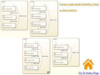
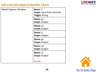
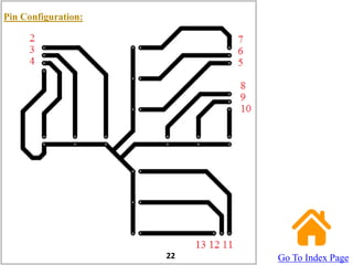
Arduino based Traffic Signal System
using MATLAB
and OrCAD
Design Process
Cycle
Table of Contents:
Step1: Required Hardwares
Step2: Required Softwares
Step3: Schematic Circuit (OrCAD)
Step4: PCB Layout (OrCAD)
Step5: Artwork (OrCAD)
Step6: Board after Etching Process in PCB Fabrication
Step7: Board after Drilling in PCB Fabrication
Step8: Component Assembling and Soldering
Step9: Timing Table for Traffic Light Signal System
Step10: Stateflow Model (MATLAB)
Step11: Logic inside Stateflow Model (MATLAB)
Step12: Add Events and Outputs to Stateflow Chart (MATLAB)
Step13: Deploy to Hardware (MATLAB)
Step14: Experiment Results
Required Hardwares:
To run this example, you need the following hardwares:
- Arduino UNO
- Arduino USB Cable
- Jumper Wires (Male-Female)
- 4 Red LEDs
- 4 Green LEDs
- 4 Yellow LEDs
- 12 pin Connector
Go To Index Page
4
Required Softwares:
To run this example, you need the following softwares installed:
- MATLAB 2014
- Arduino Hardware Support Package
- OrCAD
Go To Index Page
5
Schematic Circuit of Traffic Light Signal System:
Go To Index Page
6
PCB Layout:
Go To Index Page
5
Artwork:
Go To Index Page
8
Board after Etching Process:
Go To Index Page
9
Board after Drilling:
Go To Index Page
10
Component Assembling and Soldering:
Go To Index Page
11
Lane 1 Lane 2 Lane 3 Lane 4
10G 10R 20R 2Y
LANE 1
LANE 2
LANE 3
LANE 4
Go To Index Page
12
Lane 1 Lane 2 Lane 3 Lane 4
10G 10R 20R 2Y
2Y 10G 28R
LANE 1
LANE 2
LANE 3
LANE 4
Go To Index Page
13
Lane 1 Lane 2 Lane 3 Lane 4
10G 10R 20R 2Y
2Y 10G 28R
28R 2Y 10G
LANE 1
LANE 2
LANE 3
LANE 4
Go To Index Page
14
Lane 1 Lane 2 Lane 3 Lane 4
10G 10R 20R 2Y
2Y 10G 28R
28R 2Y 10G
8R 2Y 10G
8R
LANE 1
LANE 2
LANE 3
LANE 4
Go To Index Page
15
Make the Stateflow Model as given below:
Go To Index Page
16
Create a logic inside Stateflow Chart
as shown below:
Go To Index Page
17
Add event and output to Stateflow Chart:
Go To Index Page
18
Model Explorer Window Name: T
Scope: Input from Simulink
Trigger: Rising
Name: g1
Scope: Output
Name: y1
Scope: Output
Name: r1
Scope: Output
Name: g2
Scope: Output
Name: y2
Scope: Output
Name: r2
Scope: Output
Contd.,
Model Explorer Window Name: g3
Scope: Output
Name: y3
Scope: Output
Name: r3
Scope: Output
Name: g4
Scope: Output
Name: y4
Scope: Output
Name: r4
Scope: Output
Go To Index Page
19
Deploy to Hardware:
Click on ‘Tools’ -> Run on Target Hardware -> Prepare to Run
Target Hardware = Arduino Uno
Click ‘Deploy to Hardware’.
Go To Index Page
20
Pin Configuration:
22 Go To Index Page
Experiment Results:
Go To Index Page
23

Traffic Signal System.pptx

  • 1.
    Arduino based TrafficSignal System using MATLAB and OrCAD
  • 3.
  • 4.
    Table of Contents: Step1:Required Hardwares Step2: Required Softwares Step3: Schematic Circuit (OrCAD) Step4: PCB Layout (OrCAD) Step5: Artwork (OrCAD) Step6: Board after Etching Process in PCB Fabrication Step7: Board after Drilling in PCB Fabrication Step8: Component Assembling and Soldering Step9: Timing Table for Traffic Light Signal System Step10: Stateflow Model (MATLAB) Step11: Logic inside Stateflow Model (MATLAB) Step12: Add Events and Outputs to Stateflow Chart (MATLAB) Step13: Deploy to Hardware (MATLAB) Step14: Experiment Results
  • 5.
    Required Hardwares: To runthis example, you need the following hardwares: - Arduino UNO - Arduino USB Cable - Jumper Wires (Male-Female) - 4 Red LEDs - 4 Green LEDs - 4 Yellow LEDs - 12 pin Connector Go To Index Page 4
  • 6.
    Required Softwares: To runthis example, you need the following softwares installed: - MATLAB 2014 - Arduino Hardware Support Package - OrCAD Go To Index Page 5
  • 7.
    Schematic Circuit ofTraffic Light Signal System: Go To Index Page 6
  • 8.
    PCB Layout: Go ToIndex Page 5
  • 9.
  • 10.
    Board after EtchingProcess: Go To Index Page 9
  • 11.
    Board after Drilling: GoTo Index Page 10
  • 12.
    Component Assembling andSoldering: Go To Index Page 11
  • 13.
    Lane 1 Lane2 Lane 3 Lane 4 10G 10R 20R 2Y LANE 1 LANE 2 LANE 3 LANE 4 Go To Index Page 12
  • 14.
    Lane 1 Lane2 Lane 3 Lane 4 10G 10R 20R 2Y 2Y 10G 28R LANE 1 LANE 2 LANE 3 LANE 4 Go To Index Page 13
  • 15.
    Lane 1 Lane2 Lane 3 Lane 4 10G 10R 20R 2Y 2Y 10G 28R 28R 2Y 10G LANE 1 LANE 2 LANE 3 LANE 4 Go To Index Page 14
  • 16.
    Lane 1 Lane2 Lane 3 Lane 4 10G 10R 20R 2Y 2Y 10G 28R 28R 2Y 10G 8R 2Y 10G 8R LANE 1 LANE 2 LANE 3 LANE 4 Go To Index Page 15
  • 17.
    Make the StateflowModel as given below: Go To Index Page 16
  • 18.
    Create a logicinside Stateflow Chart as shown below: Go To Index Page 17
  • 19.
    Add event andoutput to Stateflow Chart: Go To Index Page 18 Model Explorer Window Name: T Scope: Input from Simulink Trigger: Rising Name: g1 Scope: Output Name: y1 Scope: Output Name: r1 Scope: Output Name: g2 Scope: Output Name: y2 Scope: Output Name: r2 Scope: Output Contd.,
  • 20.
    Model Explorer WindowName: g3 Scope: Output Name: y3 Scope: Output Name: r3 Scope: Output Name: g4 Scope: Output Name: y4 Scope: Output Name: r4 Scope: Output Go To Index Page 19
  • 21.
    Deploy to Hardware: Clickon ‘Tools’ -> Run on Target Hardware -> Prepare to Run Target Hardware = Arduino Uno Click ‘Deploy to Hardware’. Go To Index Page 20
  • 22.
  • 23.