Download as PDF, PPTX

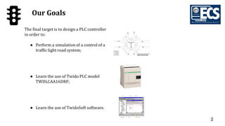
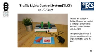
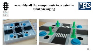
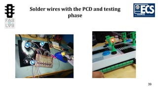
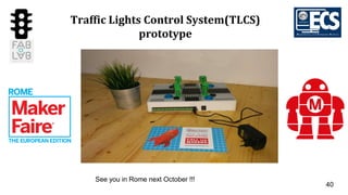
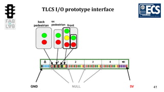
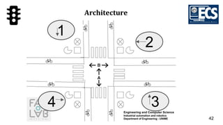
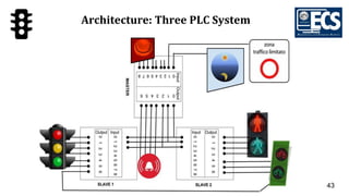
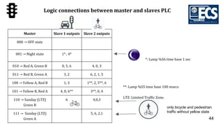
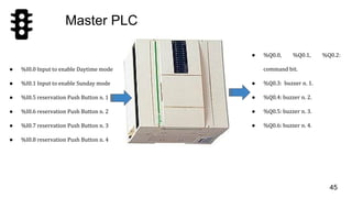
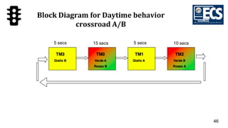
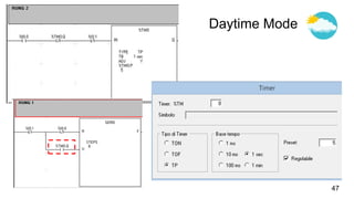
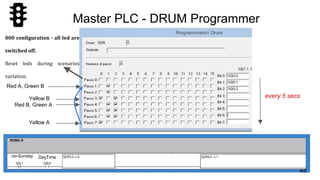
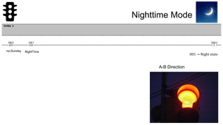
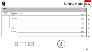
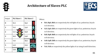
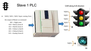

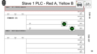
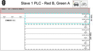
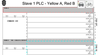
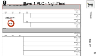
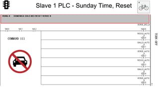
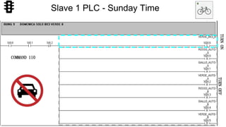
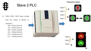
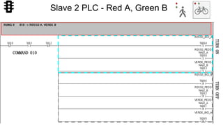
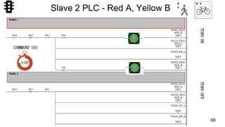
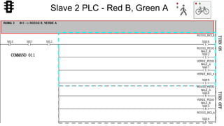
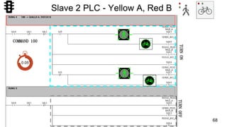
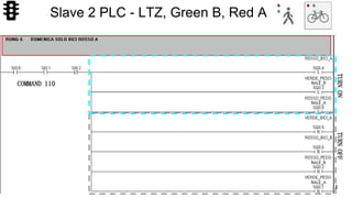
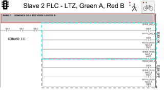


The document describes a traffic light control system using Programmable Logic Controllers (PLCs). The system uses three PLCs - a master PLC that controls two slave PLCs. The master PLC sends commands to control the light patterns at an intersection. The slave PLCs control the lights for cars and pedestrians. The system was prototyped using a PCB, 3D printed traffic lights, and packaging to test the logic implemented on the PLCs.