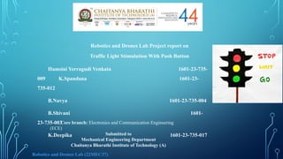
Robotics and DronesLab Project report on
Traffic Light Stimulation With Push Button
Hamsini Yerragudi Venkata 1601-23-735-
009 K.Spandana 1601-23-
735-012
B.Navya 1601-23-735-004
B.Shivani 1601-
23-735-003
K.Deepika 1601-23-735-017
Core branch: Electronics and Communication Engineering
(ECE)
Submitted to
Mechanical Engineering Department
Chaitanya Bharathi Institute of Technology (A)
Robotics and Drones Lab (22MEC37)
2.
Background &Motivation:
I and my teammates have created a traffic light simulation
circuit. There for, the circuit illustrates how traffic light is
made and the reason of it, it is obvious that, there are a lot of
types of traffic lights in the roads, like, traffic lights that are
made for 4 streets, 3 streets and others. But the circuit that I
and my teammates decided to do is for only one-way traffic
light. In my opinion, our project is pretty important because,
traffic light will organize the road movement and won’t cause
a lot of traffic on the roads.
3.
Formulation:
Traffic Lights areused to control the vehicular traffic. In the
modern era, everyone has different types of vehicles resulting in a
rise to the numbers of vehicles. That’s why traffic lights are
mandatory to avoid the traffic jams and accidents. There are three
lights in the traffic signal, having different messages for the drivers.
Red light (upper one) asks the driver to yield at the intersection,
green light (last one) gives the driver free license to drive through
the intersection whereas the yellow light (middle one) alerts the
driver to wait if the next light is red one or get ready to go / turn the
engine ON if the green light is next.
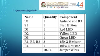
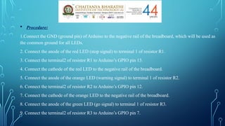
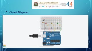
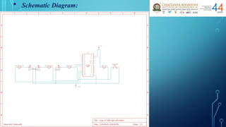
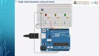
Procedure:
1.Connect theGND (ground pin) of Arduino to the negative rail of the breadboard, which will be used as
the common ground for all LEDs.
2. Connect the anode of the red LED (stop signal) to terminal 1 of resistor R1.
3. Connect the terminal2 of resistor R1 to Arduino’s GPIO pin 13.
4. Connect the cathode of the red LED to the negative rail of the breadboard.
5. Connect the anode of the orange LED (warning signal) to terminal 1 of resistor R2.
6. Connect the terminal2 of resistor R2 to Arduino’s GPIO pin 12.
7. Connect the cathode of the orange LED to the negative rail of the breadboard.
8. Connect the anode of the green LED (go signal) to terminal 1 of resistor R3.
9. Connect the terminal2 of resistor R3 to Arduino’s GPIO pin 7.
.
6.
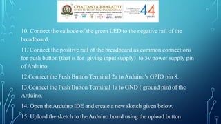
10. Connect thecathode of the green LED to the negative rail of the
breadboard.
11. Connect the positive rail of the breadboard as common connections
for push button (that is for giving input supply) to 5v power supply pin
of Arduino.
12.Connect the Push Button Terminal 2a to Arduino’s GPIO pin 8.
13.Connect the Push Button Terminal 1a to GND ( ground pin) of the
Arduino.
14. Open the Arduino IDE and create a new sketch given below.
15. Upload the sketch to the Arduino board using the upload button
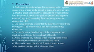
Precautions:
1. Makesure the Arduino board is not connected to a power
source while wiring up the circuit to avoid any short circuits.
2. Double-check the polarity of the LED before connecting
it to the circuit. LEDs have a positive (anode) and negative
(cathode) leg, and connecting them the wrong way can
damage the LED.
3. Use the appropriate resistor for the LED to prevent it from
burning out. The resistor value can be calculated using
Ohm's law.
4. Be careful not to bend the legs of the components too
much or too often, as they can break off easily.
5. Avoid touching any exposed wires or components while
the circuit is powered on to prevent electric shock.
6. Always disconnect the circuit from the power source
when making changes to the wiring or code.
13.
Advantages:
1.The trafficlight controller in this system can be implemented
practically, and it could be expanded further by you.
2.This traffic light controller includes a crosswalk signaling system.
3.External memory can be interface with the central controller so
that the timings are not fixed during its programming but instead
can be programmed during operation.
Limitations:
1.The project is not suitable for actual implementation but just a
demonstration of the process behind the system.
2.The project can either operated manually or by using pre-
programming operations. It cannot handle in both ways.
3.In the real-time traffic controller systems, the operator has the
right to change the timings and the intensity of the traffic light in
each lane.
14.
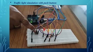
Results & Discussion:
Itwas observed that the traffic light simulation with push
button circuit now operates as follows:
The red LED turns on for 3 seconds, then turns off for 0.5
seconds.
The orange LED turns on for 1 second, then turns off for
0.5 seconds.
The green LED turns on for 2 seconds, then turns off for
0.5 seconds.
The cycle then repeats with the red LED turning on again
when push button is pressed. This cycle will continue as long
as we give input by pressing the push button to the circuit.
15.
Summary:
We learntabout the traffic lights and their importance in
maintaining public safety and order. In the process, we
learnt about light emitting diodes (LEDs), and how their use
can save energy. As programmers, we learnt two simple
commands and a program control concept called a loop.
Traffic Signals are used to control traffic and can prevent
accidents on roads. Our Overall Project is about stimulating
the traffic light signals with a push button for understanding
the rough sketch of the process and logic which is done
behind the traffic signal in daily life. Understood and
experienced the practical functioning of the components
used in this experiment. Also Acquired the knowledge
about the components and its usage in this experiment.
16.
Future scope:
Trafficlight control systems are widely used to monitor and
control the flow of automobiles through the junction of
many roads. It focuses mainly on research for safe and
efficient traffic flow, such as road geometry, sidewalks and
crosswalks, cycling infrastructure, traffic signs, road surface
markings and traffic lights. The Future scope includes
Profiling of the traffic by storing the data and managing the
traffic lights according to the collected data. The Profiling
can also be used for Traffic study and the variation in traffic
density throughout the day, week, month or a year. Further,
we can optimize this system for the emergency Vehicles such
as Ambulance. The Traffic data collected can be used to
locate different routes for a specific daily vehicle to avoid
the congestion problem.
17.
References
[1] M. Wiering,J. V. Veenen, J. Vreeken and A. Koopman. Intelligent Traffic Light
Control. Technical report, Institute of information and computing sciences, Utrecht
University, 2004.
[2] E. H. Nugrahani, L. Alamsyah and R. Ramdhan. Traffic Light Strategies in
Optimizing the Traffic Flow. Proc. of the 2nd IMT-GT Regional Conference on
Mathematics, Statistics and Applications. Malaysia. June 2006.
[3] J. Sanchez, M. Galan and E. Rubio. Applying a Traffic Lights Evolutionary
Optimization Technique to a Real Case: Las Ramblas Area in Santa Cruz de Tenerife.
Proc. of IEEE Transactions on Evolutionary Computation. February 2008, 12 (1): 25-40.
[4] Head, K. L. (1995). An Event-Based Short-Term Traffic Flow Prediction Model.
Transportation Research Record 1510, TRB, National Research Council, Washington,
D.C., 45–52.
[5] Huddart, K. W. & Wright, C. (1989a). Strategies for Urban Traffic Control. The Rees
Jeffrey’s Road Fund, Transport and Society.
[6] Huddart, K. W. & Wright, C. (1989b). Catastrophic Traffic Congestion and Some
Possible Ways of Preventing It. Proc. TRAFFEX International Traffic Engineering
Exhibition. Seminar on Congestion, Control and Parking Enforcement. Brighton, U.K.
18.
[7] Kim, Y.& Messer, C. J. (1992). Traffic signal timing
models for oversaturated signalized interchanges. TTI
Research Report, 1148-2.
[8] Shepherd, S. P. (1992). A Review of Traffic Signal
Control. Working Paper 349, Institute for Transport
Studies, Leeds, U.K
[9] Rhodes, B. W., G. J. Monteith, and M. S. Heitmann,
Microprocessor-Controlled Traffic Signal Simulation,
Course Project Report, CSSEMO, May 2002.
[10] K. N. Hewage and J. Y. Ruwanpura, "Optimization of
traffic signal light timing using simulation", Proceedings-
Winter Simulation Conference, vol. 2, pp. 1428-1433,
2004.
![ Code (or) Sketch:
int button = 0;
int leds[] = {13, 12, 7};
int c;
void setup ()
{
for (c = 0; c < 3; c++) {
pinMode(leds[c], OUTPUT);
}
pinMode (8, INPUT);
}
void loop ()
{
button = digitalRead (8);
if (button == 0) {
digitalWrite(13, HIGH);
delay (2000);
digitalWrite (13, LOW);
delay (1000);
digitalWrite (12, HIGH);
delay (2000);
digitalWrite (12, LOW);
delay (1000);
digitalWrite(7, HIGH);
delay (2000);
digitalWrite (7, LOW);
delay (1000);
}
}](https://image.slidesharecdn.com/projectpresentation-250325114744-a25b952f/85/Robotics-and-drones-Project-Presentation-pptx-7-320.jpg)
![References
[1] M. Wiering, J. V. Veenen, J. Vreeken and A. Koopman. Intelligent Traffic Light
Control. Technical report, Institute of information and computing sciences, Utrecht
University, 2004.
[2] E. H. Nugrahani, L. Alamsyah and R. Ramdhan. Traffic Light Strategies in
Optimizing the Traffic Flow. Proc. of the 2nd IMT-GT Regional Conference on
Mathematics, Statistics and Applications. Malaysia. June 2006.
[3] J. Sanchez, M. Galan and E. Rubio. Applying a Traffic Lights Evolutionary
Optimization Technique to a Real Case: Las Ramblas Area in Santa Cruz de Tenerife.
Proc. of IEEE Transactions on Evolutionary Computation. February 2008, 12 (1): 25-40.
[4] Head, K. L. (1995). An Event-Based Short-Term Traffic Flow Prediction Model.
Transportation Research Record 1510, TRB, National Research Council, Washington,
D.C., 45–52.
[5] Huddart, K. W. & Wright, C. (1989a). Strategies for Urban Traffic Control. The Rees
Jeffrey’s Road Fund, Transport and Society.
[6] Huddart, K. W. & Wright, C. (1989b). Catastrophic Traffic Congestion and Some
Possible Ways of Preventing It. Proc. TRAFFEX International Traffic Engineering
Exhibition. Seminar on Congestion, Control and Parking Enforcement. Brighton, U.K.](https://image.slidesharecdn.com/projectpresentation-250325114744-a25b952f/85/Robotics-and-drones-Project-Presentation-pptx-17-320.jpg)
![[7] Kim, Y. & Messer, C. J. (1992). Traffic signal timing
models for oversaturated signalized interchanges. TTI
Research Report, 1148-2.
[8] Shepherd, S. P. (1992). A Review of Traffic Signal
Control. Working Paper 349, Institute for Transport
Studies, Leeds, U.K
[9] Rhodes, B. W., G. J. Monteith, and M. S. Heitmann,
Microprocessor-Controlled Traffic Signal Simulation,
Course Project Report, CSSEMO, May 2002.
[10] K. N. Hewage and J. Y. Ruwanpura, "Optimization of
traffic signal light timing using simulation", Proceedings-
Winter Simulation Conference, vol. 2, pp. 1428-1433,
2004.](https://image.slidesharecdn.com/projectpresentation-250325114744-a25b952f/85/Robotics-and-drones-Project-Presentation-pptx-18-320.jpg)