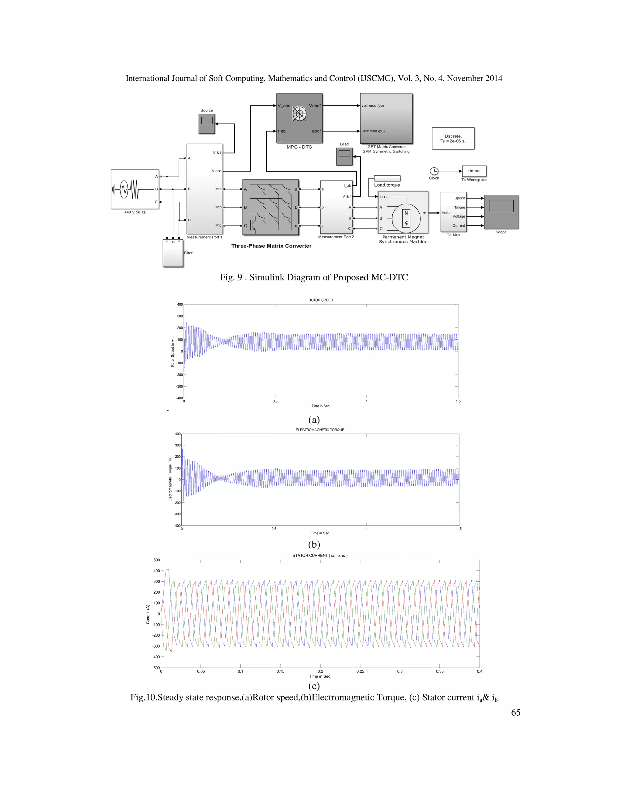
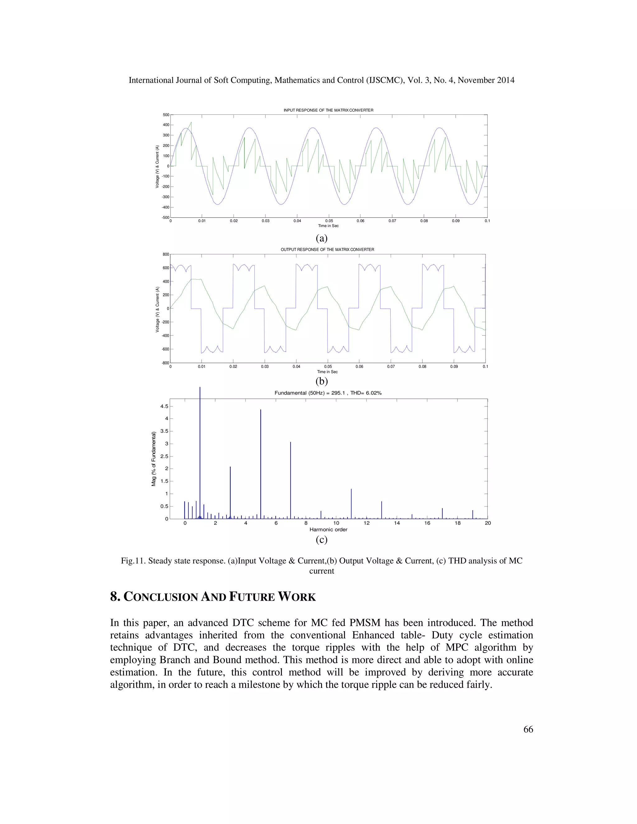
The document presents an advanced direct torque control (DTC) technique incorporating model predictive control (MPC) for matrix converter-fed permanent-magnet synchronous motor (PMSM) drives aimed at minimizing torque ripples and ensuring fixed switching frequency. It details the analytical derivation of torque and flux rate changes and compares the proposed method with existing DTC models, highlighting the benefits of reduced switching losses and improved performance. Simulation results confirm the effectiveness of this new strategy in achieving significant reduction in torque ripples for matrix converter applications.
![International Journal of Soft Computing, Mathematics and Control (IJSCMC), Vol. 3, No. 4, November 2014
DOI : 10.14810/ijscmc.2014.3404 51
TORQUE RIPPLE MINIMIZATION OF MATRIX
CONVERTER-FED PMSM DRIVES USING
ADVANCED DIRECT TORQUE CONTROL
S.Kannan1
, S.Chinnaiya2
and S.U.Prabha3
1, 2 Department of Electrical and Electronics Engineering, K.S.R. College of Engineering
Tiruchengode, India
3 Department of Electrical and Electronics Engineering, Sri Ramakrishna Engineering
College,Coimbatore, India
ABSTRACT
An advanced direct torque control (DTC) technique using Model predictive control (MPC) is proposed for
matrix converter (MC)-based permanent-magnet synchronous motor (PMSM) drive system, which reduces
the torque ripples, does not need the duty cycle calculation, and ensures the fixed switching frequency.
Analytical expressions of change rates of torque and flux of PMSM as a function of MC – dqo components
are derived. The predictive model of PMSM and MC is realized by means of State model. Then, the
advanced MC-fed DTC algorithm is implemented based on Cost function evaluation. The simulation results
exhibit remarkable torque ripple reduction with the help of MPC. As a result, the proposed strategy is
proved to be effective in minimizing the torque ripples for MC-based PMSM drives.
Keywords
Direct torque control (DTC), matrix converter (MC), permanent-magnet synchronous motor (PMSM),
Model predictive control (MPC), and Cost function
1. INTRODUCTION
The Matrix converter is a single-stage power converter, which consists of m x n bidirectional
power switches in an array form. The bidirectional switches in the converter are composed by
means of two IGBTs and two diodes connected in anti-parallel. Generally, the number of input
phases, m must be at least three, and the number of output phases, n can be chosen from one to
infinity. Currently, research works on commutation techniques [1], operation stability [2], and
control/modulation strategy [4]–[12] of MCs increase the usage of Matrix converter in many
fields like elevators, wind power generation, and mechanical manufacture [13].
A tremendous research work focusing on control and modulation strategies of MCs can be
divided into four types. They are scalar techniques, pulse width modulation (PWM), predictive
control, and direct torque control (DTC) [3].The Venturini method [4] is the first scalar technique,
which obtains the duty ratio of each switch directly by calculating the function of the
instantaneous value of the input voltage and the reference value of the output voltage. The Space
vector modulation [5] (SVM) is based on the instantaneous space vector representation of input
and output voltages and currents and it exploits the pulse width modulation, which was developed
and improved in the 1990s. The modern technique, predictive control [6], [7] evaluates the effect](https://image.slidesharecdn.com/3414ijscmc04-180530054510/75/TORQUE-RIPPLE-MINIMIZATION-OF-MATRIX-CONVERTER-FED-PMSM-DRIVES-USING-ADVANCED-DIRECT-TORQUE-CONTROL-1-2048.jpg)
![International Journal of Soft Computing, Mathematics and Control (IJSCMC), Vol. 3, No. 4, November 2014
52
of each possible switching state by a cost function. The switching state which minimizes the cost
function will be selected to output. The DTC exploits the hysteresis comparators and SVM
switching tables to obtain high-performance ac drives, was extended to MC-fed induction
machines (MC-DTC) in 2001 [8]. Normally, MC-DTC adopts hysteresis comparators and
switching tables which experiences the two major shortcomings: significant torque ripples and
variable switching frequency [14]. To overcome these drawbacks, [15] is implemented which
utilizes the duty cycle calculation. Since it reduces the torque ripples up to 30 %, it has some
disadvantages:
• It uses multilevel hysteresis and subdivided voltage vectors to reduce torque ripple.
o Discrete SVM should be produced to obtain 56 virtual voltage vectors with
different amplitude.
• Formation of switching table is offline & requires more accurate calculation.
• Exploits the duty cycle control.
o Complicated to implement &depends on motor parameters.
To avoid all these drawbacks an advanced DTC technique is proposed in this paper.
• The Model predictive control strategy is implemented with the MC – DTC fed PMSM
motor to minimize the torque ripples.
• The generalized MP-DTC [16] is approached to reduce the switching losses.
• The Branch and Bound algorithm [17] for PMSM is carried out to reduce the
computational time of Cost function.
2. MC-DTC TOPOLOGY
2.1. Principle of Matrix converter
The matrix converter having 9 bi-directional switches that allow any output phase to be connected
to any input phase. The circuit configuration is shown in Fig.1. The input terminals of the
converter are connected to a three phase power supply, while the output terminal are connected to
a three phase load, like an induction motor. The relationship between the input and output voltage
and current of MC can be expressed as
( ) ( ) ( )
( ) ( ) ( ) .
( ) ( ) ( )
a Aa Ab Ac A
b Ba Bb Bc B i
c Ca Cb Cc C
v S t S t S t v
v S t S t S t v M v
v S t S t S t v
= =
and
( ) ( ) ( )
( ) ( ) ( ) .
( ) ( ) ( )
a Aa Ba Ca A
T
b Ab Bb Cb B o
c Ac Bc Cc C
i S t S t S t i
i S t S t S t i M i
i S t S t S t i
= =
where spq(t) is the state of switch Spq, p ∈ {A,B,C}, q ∈ {a, b, c}, and MT
is the transpose of
transfer matrix M. Theoretically, the nine bi-directional switches of the matrix converter can
assume 512 (29
) different switching states . But all of them cannot be employed usefully.
(1)
(2)](https://image.slidesharecdn.com/3414ijscmc04-180530054510/75/TORQUE-RIPPLE-MINIMIZATION-OF-MATRIX-CONVERTER-FED-PMSM-DRIVES-USING-ADVANCED-DIRECT-TORQUE-CONTROL-2-2048.jpg)
![International Journal of Soft Computing, Mathematics and Control (IJSCMC), Vol. 3, No. 4, November 2014
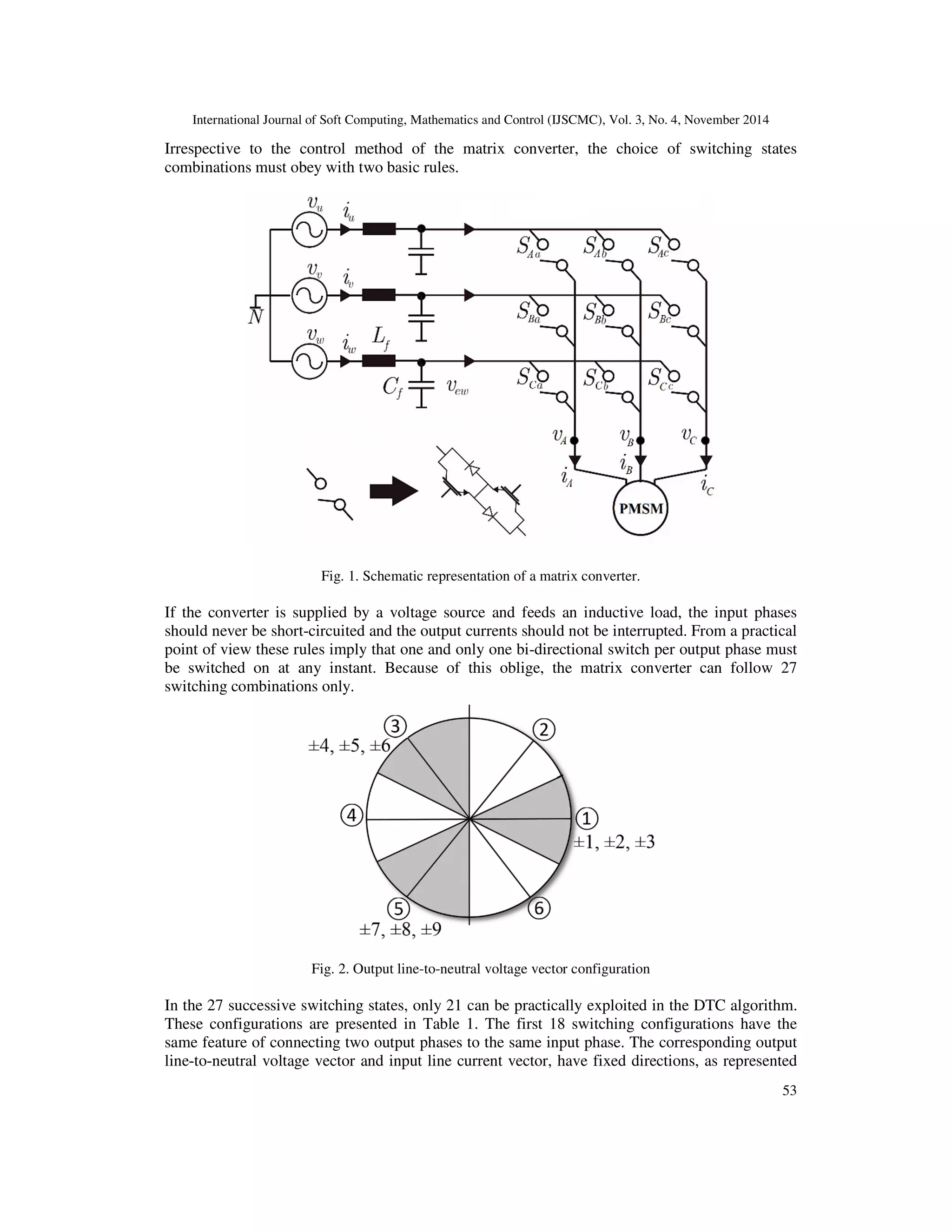
54
in Figs. 2 and 3, and will be named “active configurations.” The magnitude of these vectors
depends upon the instantaneous values of the input line-to-neutral voltages and output line
currents respectively as shown in Table 1. Three switching configurations regulate zero input
current and output voltage vectors and will be named “zero configurations.” The remaining six
switching configurations have the three output phases connected to a different input phase.
Fig. 3. Input line current vector configuration
2.2. Existing MC-DTC
Normally, the VSI-DTC employs one switching state from the VSI switching table during one
sampling period to increase or decrease motor torque or flux [18]. The output voltage vectors of
MC have the same direction as those delivered by a VSI (V1 − V6), as shown in Fig. 2. Hence,
MC-DTC based on VSI-DTC can adjust the input power factor on the grid side and torque and
flux on the motor side at the same time, by means of the second selection of switching states. In
Fig. 2, the space is equally divided into six sectors, which are indexed by hα (α = 1, 2, . . . , 6),
with the first sector covering from−π/6 to π/6. As a result, in each sector, there are two output
voltage vectors that have the same direction as that of the VSI vector, and their related input
current vectors just lie on different sides of the input voltage vector, in which way the phase
between input voltages and currents could be controlled.
The schematic diagram of the Existing MC-DTC [15] is presented in Fig. 4. One desired virtual
VSI voltage vector is selected from the VSI switching table (see Table 2). Then, one MC
switching state is employed [15] from Table 3 based on the virtual VSI voltage vector. When a
zero-voltage vector is required from Table 2, the zero configuration of the MC, which minimizes
the number of commutations, is selected. The torque and flux are estimated, as shown in the
lower part of Fig. 4, in which the required output voltage and input current can be obtained from
the input voltage, output current, and transfer matrix M.
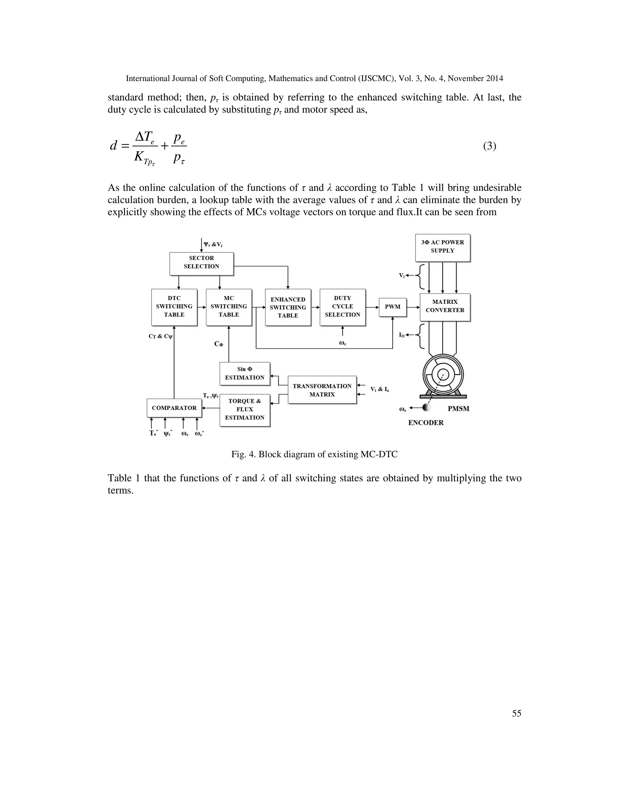
2.3. Duty cycle calculation
It can be seen that an enhanced switching table and a duty cycle calculation part are added based
on the standard method as shown in fig. 4. At first, an active voltage vector is chosen using the](https://image.slidesharecdn.com/3414ijscmc04-180530054510/75/TORQUE-RIPPLE-MINIMIZATION-OF-MATRIX-CONVERTER-FED-PMSM-DRIVES-USING-ADVANCED-DIRECT-TORQUE-CONTROL-4-2048.jpg)

![International Journal of Soft Computing, Mathematics and Control (IJSCMC), Vol. 3, No. 4, November 2014
57
Table 3. MC switching table
hα Cφ
VSI Vectors
V1 V2 V3 V4 V5 V6
①①①①
+1 -3 +9 -6 +3 -9 +6
-1 +1 -7 +4 -1 +7 -4
②②②②
+1 +2 -8 +5 -2 +8 -5
-1 -3 +9 -6 +3 -9 +6
③③③③
+1 -1 +7 -4 +1 -7 +4
-1 +2 -8 +5 -2 +8 -5
④④④④
+1 +3 -9 +6 -3 +9 -6
-1 -1 +7 -4 +1 -7 +4
⑤⑤⑤⑤
+1 -2 +8 -5 +2 -8 +5
-1 +3 -9 +6 -3 +9 -6
⑥⑥⑥⑥
+1 +1 -7 +4 -1 +7 -4
-1 -2 +8 -5 +2 -8 +5
3. MATHEMATICAL MODELLING OF PMSM
In the rotating d-q frame, the dynamics of the surface mounted PMSM is described as [19]
( ) 1
( ) ( ( ) )mr
r e m
m m
Bd t
t T t T
dt J J
ω
ω= − + −
( ) 1
( ) ( ) ( ) ( )d s
d e d d
di t R
i t t i t v t
dt L L
ω= − + +
( ) 1 1
( ) ( ) ( ) ( ) ( )
q s
q e d e m q
di t R
i t t i t t v t
dt L L L
ω ω λ=− − − +
where ωr(t) is the rotor speed, ωe(t) is the electrical rotational rotor speed, id(t) and iq(t) are the
stator current in d-q frame, respectively. The electromagnetic torque of PMSM is expressed as
[20]
3 | |
2 sin | | ( )sin 2
4
s
e f q s q d
d q
p
T L L L
L L
ψ
ψ δ ψ δ = − −
where δ is the displacement angle between the stator and permanent-magnet flux linkage, ψf is the
permanent-magnet flux, Ld and Lq are the direct and quadrature stator inductances, respectively,
and p is the number of pole pairs. From (7), the change rate of torque can be derived as
3 | |
cos | | ( )cos2
2
s
e f q s q d
d q
pd d
T L L L
dt L L dt
ψ δ
ψ δ ψ δ = − −
The derivative of δ is given by
(4)
(5)
(6)
(7)
(8)](https://image.slidesharecdn.com/3414ijscmc04-180530054510/75/TORQUE-RIPPLE-MINIMIZATION-OF-MATRIX-CONVERTER-FED-PMSM-DRIVES-USING-ADVANCED-DIRECT-TORQUE-CONTROL-7-2048.jpg)
![International Journal of Soft Computing, Mathematics and Control (IJSCMC), Vol. 3, No. 4, November 2014
58
( )s r
s r
dd
dt dt
θ θδ
ω ω
−
= = −
where θs and θr are the stator and rotor positions, respectively, and ωr is the rotor electrical
angular velocity.
4. ADVANCED DTC
In this paper, the generalized DTC scheme with Model Predictive control is approached in Fig.5.
Here predictive control consists a model of the whole converter and PMSM in order to predict the
system behaviour after a computation period for each possible MC configuration. After that a cost
function will be used to determine the configuration which is to be applied for the next computing
period.
4.1. Model Predictive control
In Model Predictive Control [21], the current control input is attained by solving at each sampling
instant an inhibited optimal control problem based on the predictions delivered by an internal
model of the controlled process. Generally the optimal control problem is formulated over a finite
or infinite horizon. The underlying optimization procedure profits an optimal control sequence
which minimizes an objective function. The first control input of this sequence is applied in
accordance with the so called receding horizon policy. At the next sampling instant, the control
sequence is recomputed over a shifted horizon, thus providing feedback.
4.2. Receding horizon policy
The MPC algorithm finds the sequence of optimal input u(k) that satisfies given constraints [22].
From that sequence of optimal input u(k), only the first input is applied to plant for next sampling
interval. The whole process is repeated for next samples. This method of optimization of u is
known as online optimization. The prediction horizon keeps on shifting towards right after each
sample and the size of prediction horizon remains constant as shown in fig. 6. So that this
mechanism is termed as receding horizon policy.
(9)](https://image.slidesharecdn.com/3414ijscmc04-180530054510/75/TORQUE-RIPPLE-MINIMIZATION-OF-MATRIX-CONVERTER-FED-PMSM-DRIVES-USING-ADVANCED-DIRECT-TORQUE-CONTROL-8-2048.jpg)
![International Journal of Soft Computing, Mathematics and Control (IJSCMC), Vol. 3, No. 4, November 2014
59
Fig. 5. Block diagram of Advanced MC-DTC.
4.3. Modelling of MP-DTC scheme
4.3.1. Permanent Magnet Synchronous Machine Model
The PMSM can be modelled with the help of state space equations in the dq rotor frame (10)
where Id, Iq and Vd, Vq are stator currents and voltages expressed in the dq frame, R and L are the
stator winding resistor and inductance respectively, ω is the rotor angular speed and φ is the flux
produced by permanent magnets [22].
( )
1
( ) 0 0( )( )
. . ( ) ( )
( )( ) 1 ( )
( ) 0
tdd
d q
qq
R
t I tI t L L
V t V t
I tI t R t
t
L L L
ω
φ
ω
ω
−
= + − − −
&
&
The Model parameters (R, L and φ) can be considered as constant and rotor electrical speed (ω)
variations can be abandoned for a short sampling period T of the algorithm. Hence the following
model can be found with a first order Euler integration.
01 ( ) 0( 1) ( ) ( )
. .
( 1) ( ) ( ) ( )
( ) 1 0
d d d
q q q
RT T
T kI k I k V kL L
T
I k I k V kRT T k
T k L
L L
ω
φ
ω
ω
− + = + + + − − −
( )
( 1) ( ). ( ) ( )
( )
d
q
V k
X k A k X k B k
V k
+ = + + Φ
(10)
(11)
(12)](https://image.slidesharecdn.com/3414ijscmc04-180530054510/75/TORQUE-RIPPLE-MINIMIZATION-OF-MATRIX-CONVERTER-FED-PMSM-DRIVES-USING-ADVANCED-DIRECT-TORQUE-CONTROL-9-2048.jpg)
![International Journal of Soft Computing, Mathematics and Control (IJSCMC), Vol. 3, No. 4, November 2014
60
where X(k) = [Id(k) Iq(k) ]t
B is a constant matrix, and normally A and Φ depend on rotation
speed. Vd, Vq must be expressed as functions of converter switching states in order to obtain a
model of the whole converter - machine.
4.3.2. Matrix Converter Model
The dq-voltages Vd and Vq can be expressed as functions of output voltages [Va Vb Vc]t
by using
rotation matrix as,
cos( ( )) sin ( ( ))
( ( ))
sin ( ( )) cos( ( ))
k k
R k
k k
θ θ
θ
θ θ
=
−
1 1
( )1
( ) 2 2 2
( ( )). . ( )
( ) 3 3 3
( )0
2 2
a
d
b
q
c
V k
V k
R k V k
V k
V k
θ
− − = − −
Also the output voltage can be expressed as function of input voltages with the following
intellectual. Let λκ (λ = A,B,C and κ = a, b, c) as the switch between phases λ and κ. Let define uλκ
as an integer that represent the switch state with the following convention: if uλκ = 0 then the
switch λκ is open; if uλκ = 1 then the switch λκ is closed. In a matrix converter, between the three
switches connected to an output phase, one and only one switch can be closed. Certainly if more
than one switch is closed, there will be a short circuit of the voltage supply and if none is closed,
there is no path for the output phase current. For example, for the phase a, this lead to
1Aa Ba Cau u u+ + =
and
1
1
1
Aa a A
Ba a B
Ca a C
u V V
u V V
u V V
= → =
= → =
= → =
Then
a Aa A Ba B Ca CV u V u V u V= + +
As a result output voltages can be expressed as function of input voltages with (18).
( ) ( ) ( ) ( ) ( )
( ) ( ) ( ) ( ) . ( )
( ) ( ) ( ) ( ) ( )
a Aa Ba Ca A
b Ab Bb Cb B
c Ac Bb Cc C
V k u k u k u k V k
V k u k u k u k V k
V k u k u k u k V k
=
(13)
(14)
(15)
(18)
(16)
(17)](https://image.slidesharecdn.com/3414ijscmc04-180530054510/75/TORQUE-RIPPLE-MINIMIZATION-OF-MATRIX-CONVERTER-FED-PMSM-DRIVES-USING-ADVANCED-DIRECT-TORQUE-CONTROL-10-2048.jpg)
![International Journal of Soft Computing, Mathematics and Control (IJSCMC), Vol. 3, No. 4, November 2014
61
Also the Eqn (15) can be written for phase b and c; by the way there are 27 allowable switching
configurations for a three-phase to three-phase matrix converter. These converter configurations
can be divided into three groups. In the first one, each output phase is connected to a different
input phase (e.g. uAa = uBb = uCc = 1). The corresponding output voltage vectors (in the αβ stator
frame) have a constant amplitude and a variable direction. There is six configurations in this
group. In the second group, each output phase is connected to the same input phase (e.g. uAa = uBb
= uCc = 1) There is three configurations in this group. They lead to a null output voltage vector.
Finally the eighteen other configurations are in the third group. Two outputs are connected to the
same input (e.g. uAa = uBb = uCc = 1). The corresponding output voltage vectors (in the αβ stator
frame) have a constant direction and a variable amplitude. It is worth to note that, for each paper
cited in reference, the six configurations from the first group are not considered. Predictive
control can use these configurations.
4.3.3. Model of the whole converter – machine
Firstly with (1), (2) and (18), if output currents, input voltages (V in = [VA VB Vc ]T
) , angular
position and speed are measured, it is possible to predict every possible state vector after a
sampling period Xn(k + 1) (1 ≤ n ≤ 27) for each possible converter configuration Un (19).
( 1) ( ). ( ) . ( ( )). . ( ). ( ) ( )n n inX k A k X k B R k C U k V k kθ+ = + +Φ
Secondly as it is possible to achieve for currents a similar reasoning than the one used to
demonstrate (18), it is also possible to predict input currents in a fixed frame AB after a sampling
period for each converter configuration (20).
1
1 1 1 1
1 1
( 1) 2 2 2 2 2
. ( ).
( 1) 3 3 3 3 3
0 0
2 2 2 2
( 1)
. ( ) .
( 1)
An t
n
Bn
An
Bn
I k
U k
I k
I k
R k
I k
−
− − − − +
=
+ − −
+
+
4.3.4. Cost Function
A cost function is used to determine which configuration must be applied. As the main goal of the
control scheme is to control output currents, a first cost function is proposed as the sum of
differences between the reference currents Id
#
, Iq
#
and the predicted currents (21).
' # #
| ( 1)| | ( 1)| .|sin( ( 1))|n d dn q qn inG I I k I I k c kφ= − + + − + + +
With this cost function, only output currents are controlled. However the matrix converter
structure also allows to control input power factor. So input currents are computed with (20) in
order to compute the angle between input current vector and input voltage vector if the
configuration n is applied (φin). Then a third term is added in (21) to take into account input
power factor and in order to make it as close to unity as possible (22).
(19)
(20)
(21)](https://image.slidesharecdn.com/3414ijscmc04-180530054510/75/TORQUE-RIPPLE-MINIMIZATION-OF-MATRIX-CONVERTER-FED-PMSM-DRIVES-USING-ADVANCED-DIRECT-TORQUE-CONTROL-11-2048.jpg)
![International Journal of Soft Computing, Mathematics and Control (IJSCMC), Vol. 3, No. 4, November 2014
62
' # #
| ( 1)| | ( 1)| .|sin( ( 1))|n d dn q qn inG I I k I I k c kφ= − + + − + + +
(a)
(b)
Fig.6. MPC operating principle. (a)Theoretical case. (b) Implementation case
In (22) c is a weighting factor. Actually the instantaneous angle between input current vector and
input voltage vector is used as a way to act on input power factor. With c, it is possible to obtain a
trade-off between output current control and input power factor controls.
5. BRANCH AND BOUND ALGORITHM FOR MPC
The Prediction of future behaviour is not very simple from computational cost point of view. It
becomes really complex when prediction is to be made for few samples. The B&B approach [17]
is based on the total set of feasible solutions that can be partitioned into subset of solutions which
are estimated to get the finest solution [24]. Bounding value is the maximum cost at which the
particular solution will be discarded and should not be branched further. Branch and bound
scheme reduces the computational cost in three ways:
• Previous switching position of the MC is considered as the root node which is further
branched to its eight possible positions. Then each of the eight possible switching positions
(22)](https://image.slidesharecdn.com/3414ijscmc04-180530054510/75/TORQUE-RIPPLE-MINIMIZATION-OF-MATRIX-CONVERTER-FED-PMSM-DRIVES-USING-ADVANCED-DIRECT-TORQUE-CONTROL-12-2048.jpg)

![International Journal of Soft Computing, Mathematics and Control (IJSCMC), Vol. 3, No. 4, November 2014
67
REFERENCES
[1] H. She, H. Lin, B. He, X. Wang, L. Yue, and X. An, “Implementation of voltage-based commutation
in space-vector-modulated matrix converter,” IEEE Trans. Ind. Electron., vol. 59, no. 1, pp. 154–166,
Jan. 2012.
[2] C. Xia, P. Song, T. Shi, and Y. Yan, “Chaotic dynamics characteristic analysis for matrix converter,”
IEEE Trans. Ind. Electron., vol. 60, no. 1, pp. 78–87, Jan. 2013.
[3] J. Rodriguez, M. Rivera, J. Kolar, and P. Wheeler, “A review of control and modulation methods for
matrix converters,” IEEE Trans. Ind. Electron., vol. 59, no. 1, pp. 58–70, Jan. 2012.
[4] M. Venturini, “A new sine wave in sine wave out, conversion technique which eliminates reactive
elements,” in Proc. Powercon 7, 1980, pp. E3/1–E3/15.
[5] X. Wang, H. Lin, H. She, and B. Feng, “A research on space vector modulation strategy for matrix
converter under abnormal input-voltage conditions,” IEEE Trans. Ind. Electron., vol. 59, no. 1, pp.
93–104, Jan. 2012.
[6] M. Rivera, A. Wilson, C. A. Rojas, J. Rodriguez, J. R. Espinoza, P. W. Wheeler, and L. Empringham,
“A comparative assessment of model predictive current control and space vector modulation in a
direct matrix converter,” IEEE Trans. Ind. Electron., vol. 60, no. 2, pp. 578–588, Feb. 2013.
[7] S. Kouro, P. Cortes, R. Vargas, U. Ammann, and J. Rodriguez, “Model predictive control, a simple
and powerful method to control power converters,” IEEE Trans. Ind. Electron., vol. 56, no. 6, pp.
1826–1838, Jun. 2009.
[8] D. Casadei, G. Serra, and A. Tani, “The use of matrix converters in direct torque control of induction
machines,” IEEE Trans. Ind. Electron., vol. 48, no. 6, pp. 1057–1064, Dec. 2001.
[9] C. Ortega, A. Arias, C. Caruana, J. Balcells, and G. Asher, “Improved waveform quality in the direct
torque control of matrix-converter-fed PMSM drives,” IEEE Trans. Ind. Electron., vol. 57, no. 6, pp.
2101–2110, Jun. 2010.
[10] K.-B. Lee and F. Blaabjerg, “Sensorless DTC-SVM for induction motor driven by a matrix converter
using a parameter estimation strategy,” IEEE Trans. Ind. Electron., vol. 55, no. 2, pp. 512–521, Feb.
2008.
[11] J. Wang and J. Jiang, “Variable-structure direct torque control for induction motor driven by a matrix
converter with over modulation strategy,” in Proc. 6th IEEE IPEMC, May 2009, pp. 580–584.
[12] D. Xiao and M. F. Rahman, “Sensorless direct torque and flux controlled IPM synchronous machine
fed by matrix converter over a wide speed range,” IEEE Trans. Ind. Informat., vol. 9, no. 4, pp. 1855–
1867, Nov. 2013.
[13] E. Yamamoto, H. Hara, T. Uchino, M. Kawaji, T. J. Kume, J.-K. Kang, and H.-P. Krug,
“Development of MCs and its applications in industry,” IEEE Ind. Electron. Mag., vol. 5, no. 1, pp.
4–12, Mar. 2011.
[14] G. S. Buja and M. P. Kazmierkowski, “Direct torque control of PWM inverter-fed ac motors—A
survey,” IEEE Trans. Ind. Electron., vol. 51, no. 4, pp. 744–757, Aug. 2004.
[15] C.Xia, J.Zhao, Y.Yan, and T.Shi , “A Novel Direct Torque Control of Matrix Converter-Fed PMSM
Drives Using Duty Cycle Control for Torque Ripple Reduction,” IEEE Trans.Ind.Electron, vol. 61,
no. 6, pp. 2700-2713, Jun. 2014.
[16] T.Geyer, and G.Papafotiou, “Model Predictive Direct Torque Control of a Variable Speed Drive with
a Five-Level Inverter”, IEEE Industrial Electronics, 35th Annual Conference , pp.1203-1208, Nov.
2009
[17] M. A. Naeem, and K. M. Hasan , “Direct Torque Control (DTC) of Three Phase Induction Motor
using Model based Predictive Control (MPC) scheme deploying Branch and Bound Algorithm”,
ICRERA 2013, Madrid, Spain, Oct. 2013
[18] I. Takahashi and T. Noguchi, “A new quick response and high efficiency control strategy for an
induction motor,” IEEE Trans. Ind. Electron., vol. IE-22, no. 5, pp. 820–827, Sep. 1986.
[19] J. Zhoua and Y. Wang, “Real-time nonlinear adaptive back stepping speed control for a PM
synchronous motor,” Control Eng. Pract., vol. 13, pp. 1259– 1269, 2005.
[20] L. Zhong, M. Rahman, W. Hu, and K. Lim, “Analysis of direct torque control in permanent magnet
synchronous motor drives,” IEEE Trans. Power Electron., vol. 12, no. 3, pp. 528–536, May 1997.
[21] C. E. Garcia, D. M. Prett, and M. Morari, “Model predictive control: Theory and practice – a survey,”
Automatica, vol. 25, no. 3, pp. 335–348, Mar. 1989.](https://image.slidesharecdn.com/3414ijscmc04-180530054510/75/TORQUE-RIPPLE-MINIMIZATION-OF-MATRIX-CONVERTER-FED-PMSM-DRIVES-USING-ADVANCED-DIRECT-TORQUE-CONTROL-17-2048.jpg)
![International Journal of Soft Computing, Mathematics and Control (IJSCMC), Vol. 3, No. 4, November 2014
68
[22] M.Fan, H.Lin , and T.Lan , “Model Predictive Direct Torque Control for SPMSM with Load Angle
Limitation”, Progress In Electromagnetics Research B, Vol. 58, 245 -256, Mar.2014
[23] M. Pacas and J. Weber, “Predictive direct torque control for the PM synchronous machine,” IEEE
Trans. Ind. Electron., vol. 52, no. 5, pp. 1350–1356, Oct. 2005.
[24] T. Geyer, “Low complexity model predictive control in power electronics and power systems,” Ph.D.
dissertation, Automatic Control Laboratory ETH Zurich, 2005.
Authors
Mr.S.Kannan , He completed his B.E in Electrical and Electronics Engineering from
Sasurie College of Engineering, Tirupur, India and currently doing M.E in K.S.R. College of
Engineering ,Tiruchengode, India. He worked as a Lecturer in M.Kumarasamy College of
Engineering, Karur, India for 2 years. His area of interest includes Electrical Machines,
Power Electronics & Soft computing Techniques.
Mr.S.Chinnaiya, He completed his M.E in Power Electronics and Drives from Anna
University, Chennai, India and pursuing Ph.D under Anna University, Chennai. He is a
lifetime member in ISTE. At present he is working as an Assistant Professor in EEE
Department at KSR College of Engineering, Tiruchengode, India. His area of interest includes
Matrix Converter, Power Quality, and Intelligent Controllers.
Dr.S.U.Prabha, She completed her M.E. in Electrical Machines from Bharathiar University,
Coimbatore, India and her Ph.D in Power Systems from Multimedia University, Malaysia. She
is a lifetime member in ISTE and also a member of IEEE. At present she is working as a
Professor and Head in EEE Department at Sri Ramakrishna Engineering College, Coimbatore,
India. She is a reviewer for various International Journals. She has published more than 20 research papers
in various International Journals and Conferences. Her areas of interest are Power Systems and Electrial
Machines.](https://image.slidesharecdn.com/3414ijscmc04-180530054510/75/TORQUE-RIPPLE-MINIMIZATION-OF-MATRIX-CONVERTER-FED-PMSM-DRIVES-USING-ADVANCED-DIRECT-TORQUE-CONTROL-18-2048.jpg)
![[9_CV] FCS-Model Predictive Control of Induction Motors feed by MultilLevel C...](https://cdn.slidesharecdn.com/ss_thumbnails/9cvfcs-modelpredictivecontrolofinductionmotorsfeedbymultillevelcasadedh-bridgeinverter-190418083950-thumbnail.jpg?width=640&height=640&fit=bounds)


![[1_CV] Model Predictive Control Method for Modular Multilevel Converter Appli...](https://cdn.slidesharecdn.com/ss_thumbnails/1cvmodelpredictivecontrolmethodformodularmultilevelconverterapplications-190418082702-thumbnail.jpg?width=640&height=640&fit=bounds)