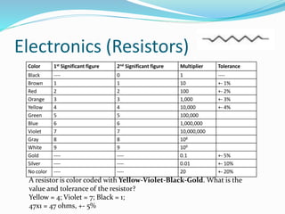
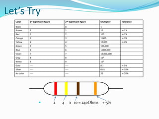
The document discusses drafting and related topics. It defines drafting as the process of drawing to communicate ideas and instructions to others. It then describes common drafting equipment like T-squares, triangles, and pencils. It explains different types of drawings like orthographic, isometric, and pictorial. It also covers lettering guidelines, types of lines used in drawings, and sample questions.


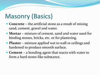
![Lettering (Guidelines)
[1]Cap line – the uppermost line for uppercase letters
and for ascender.
[2]Waist line – line between Cap and Base lines, used
to determine the height of the lower case letters.
[3]Base line – line where all the letters rest or stand.
[4]Drop line – a line for letters with strokes that
extend downward known as descender.
Day
[1]
[2]
[3]
[4]](https://image.slidesharecdn.com/tle-revewer-ppt-230823225429-16f9ee8d/85/Tle-Reviewer-Ppt-pptx-8-320.jpg)

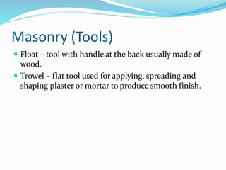
![Drafting (Lines)
[1]Dimension line - used to indicate the measurement of objects
which are represented by dark solid lines.
[2]Extension line – fine line used to show clearly the dimension
limits.
[3]Center line – light broken lines used in circles, sometimes as
extension line
[4]Leader line – line leading from a dimension value, or explanatory
note to the feature on the drawing. An arrowhead is used in pointing
end but not in note end.
[5]Long break – a limiting line used to limit the length of elongated
object.
[6]Invisible line - a series of light dash line that represents parts of a
drawing that are not seen.
Border line - is considered as the darkest lines that surround a
drawing usually in rectangular shape](https://image.slidesharecdn.com/tle-revewer-ppt-230823225429-16f9ee8d/85/Tle-Reviewer-Ppt-pptx-10-320.jpg)
![Drafting (Lines)
3’’
[1]Dimension line
[2]Extension line
[3]Center line
[4]Leader line
[5]Long break
[6]Invisible line
[1]
[2]
[3]
[4]
[5]
[6]](https://image.slidesharecdn.com/tle-revewer-ppt-230823225429-16f9ee8d/85/Tle-Reviewer-Ppt-pptx-11-320.jpg)