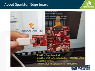
Reset Button
UART connector
GPIOButton
MICx2
Qwiic connector
GPIO connections x4
Bluetooth Radio
LED x4
Camera connector
JTAG Connector
Accelerometer
MCU
7.
Linux 系統
• 目的:Building the firmware for Sparkfun Edge Board
• OS: Ubuntu 18.04
**可參考本文章 ” Virtual Box建置Linux主機”
https://bit.ly/2RE0hK8
Windows 系統
• 目的: Training the Tensor flow model
• 所需軟體:
• Anaconda https://www.anaconda.com
• Python 3.7 and TensorFlow 2.0
• MobaXterm https://mobaxterm.mobatek.net/
• Serial to USB driver (CH340)
準備好軟體開發環境
1.) 先將Sparkfun 透過USB 線連接 PC
2.) 再檢查所有USB-to-Serial裝置
• Linux : 在終端機輸入 ls /dev/ttyUSB0
• MacOS : 輸入 ls /dev/cu.usbserial*
• Windows : 在裝置管理員檢查COM (此處為COM14)
燒入前檢查
Windows 須先安裝CH340 Driver
15.
遵循以下步驟
1. 確認 Sparkfunedge board已經連接到 PC (USB-to-Serial 轉板 )
2. 先持續按著Button 14, 再按 button RST (進入燒錄模式)
3. 接著在[Anaconda Prompt ],
要切換到 apollo3_scripts 目錄, 輸入下列指令
python uart_wired_update.py COM14 -f example1_edge_test_wire.bin
在windows上燒錄bin檔到edge board
*須先安裝pyserial 套件
pip install pyserial
COM14 不能被其他程式佔用!!
COM14 is your COM PORT NUMBER
You can useTeraTerm or putty
Display the output message from Edge board
[Setup->Serial Port ]
baud rate: 115200 bps, 8 N 1
18.
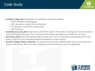
Code Architecture
• UARTprinting for info/debugging
• ADC operation to sample from a microphone
• I2C operation to control the accelerometer
• GPIO functions (an output that can drive up to 12 mA)
"hal/am_hal_adc.h"
"hal/am_hal_gpio.h"
"hal/am_hal_uart.h"
mcu/apollo3/am_mcu_apollo.h
……………
MCU
pin
Board (Sparkfun Edge)
./boards/SparkFun_Edge_BSP-
master/bsp/am_bsp_pins.h
Application
MCU register R/W
Hardware
Abstraction Layer
(HAL)


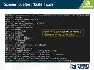
![產生燒錄檔 & 寫入燒錄檔到板子
Genearte firmware 產生燒錄檔 xxx_wire.bin
====================
[on Linux]
cd apollo3_scripts
#copy xxx.bin to here
cp ../tensorflow/lite/micro/tools/make/gen/sparkfun_edge_cortex-m4/bin/
example1_edge_test.bin .
./build_fw.sh example1_edge_test.bin
==> example1_edge_test_wire.bin](https://image.slidesharecdn.com/1tinymlsparkfun-210530062054/85/Tiny-ML-for-spark-Fun-Edge-12-320.jpg)

![遵循以下步驟
1. 確認 Sparkfun edge board已經連接到 PC (USB-to-Serial 轉板 )
2. 先持續按著Button 14, 再按 button RST (進入燒錄模式)
3. 接著在[Anaconda Prompt ],
要切換到 apollo3_scripts 目錄, 輸入下列指令
python uart_wired_update.py COM14 -f example1_edge_test_wire.bin
在windows上燒錄bin檔到edge board
*須先安裝pyserial 套件
pip install pyserial
COM14 不能被其他程式佔用!!
COM14 is your COM PORT NUMBER](https://image.slidesharecdn.com/1tinymlsparkfun-210530062054/85/Tiny-ML-for-spark-Fun-Edge-15-320.jpg)

![You can use TeraTerm or putty
Display the output message from Edge board
[Setup->Serial Port ]
baud rate: 115200 bps, 8 N 1](https://image.slidesharecdn.com/1tinymlsparkfun-210530062054/85/Tiny-ML-for-spark-Fun-Edge-17-320.jpg)