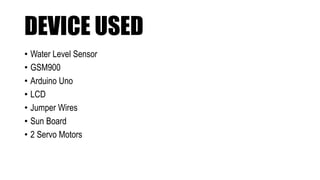
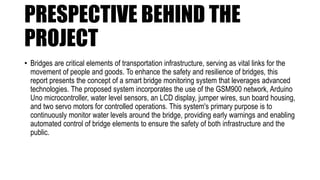
Arduino for beginners(ECE 281)
NAME ROLL NO. R.ID SIGN. MARKS
Anmol 36 12222128 Anmol
Yatharth 37 12222247 Yatharth
Aryan 38 12222304 Aryan
Avinash 39 12222310 Avinash
Submitted by:-
Submitted to :-> Suverna Sengar
THE SMART
BRIDGE
DEVICE USED
• Water Level Sensor
• GSM900
• Arduino Uno
• LCD
• Jumper Wires
• Sun Board
• 2 Servo Motors
PRESPECTIVE BEHIND THE
PROJECT
• Bridges are critical elements of transportation infrastructure, serving as vital links for the
movement of people and goods. To enhance the safety and resilience of bridges, this
report presents the concept of a smart bridge monitoring system that leverages advanced
technologies. The proposed system incorporates the use of the GSM900 network, Arduino
Uno microcontroller, water level sensors, an LCD display, jumper wires, sun board housing,
and two servo motors for controlled operations. This system's primary purpose is to
continuously monitor water levels around the bridge, providing early warnings and enabling
automated control of bridge elements to ensure the safety of both infrastructure and the
public.
1.INTRODUCTION
• Bridges are fundamental components of any transportation network, providing critical connections over bodies of water,
ravines, and challenging terrain. Ensuring the safety and functionality of bridges is paramount for public safety and the
efficient operation of transportation systems. While bridges are designed to withstand various environmental challenges,
they can still be susceptible to damage from natural disasters, particularly flooding.
• In this report, we introduce a concept for a Smart Bridge Monitoring System, which utilizes a combination of electronic
components, including the GSM900 network, Arduino Uno microcontroller, water level sensors, an LCD display, jumper
wires, sun board housing, and two servo motors. This system is designed to continuously monitor water levels around the
bridge, collect data, and provide early warnings in the event of rising water levels, which could potentially pose a threat to
the bridge's structural integrity or the safety of people using it.
2. Components Used
• 2.1. GSM900 Module
The GSM900 module serves as the communication backbone of the smart bridge monitoring system. It enables wireless
data transmission and reception, facilitating real-time monitoring and communication between the bridge's monitoring
system and a central server or control station. This communication is crucial for timely responses and remote control.
• 2.2. Arduino Uno
The Arduino Uno microcontroller is the central processing unit of the system. It is responsible for data acquisition,
processing, decision-making, and control of other components. The Arduino Uno is programmed to interface with various
sensors, collect data, analyze it, and trigger responses as necessary.
•
• 2.3. Water Level Sensor
Water level sensors are strategically placed around the bridge's vicinity to continuously measure the water levels in adjacent
bodies of water, such as rivers, streams, or reservoirs. These sensors employ various technologies, such as ultrasonic or
float-type sensors, to provide accurate and reliable data regarding water levels.
• 2.4. LCD Display
The LCD (Liquid Crystal Display) is an essential user interface component. It is employed for local monitoring and
debugging purposes. The LCD displays real-time data on water levels, system status, and any alerts, allowing maintenance
personnel or on-site engineers to quickly assess the situation
• 2.5. Jumper Wires
Jumper wires play a crucial role in the system by establishing electrical connections between various components. They
serve to maintain an organized and efficient wiring infrastructure, ensuring the seamless flow of data and control signals
throughout the system.
• 2.6. Sun Board
The sun board, made of durable and weather-resistant materials, serves as the housing for the smart bridge monitoring
system. Its primary function is to protect the electronic components from environmental elements such as rain, sunlight, and
dust. Additionally, the sun board is designed to be robust, ensuring the system's durability and longevity.
• 2.7. Servo Motors
Two servo motors are integrated into the system to enable controlled and automated actions on the bridge. These motors
can be used to manipulate specific bridge elements, such as barriers or gates, to regulate access. For instance, if rising
water levels pose a potential threat, the servo motors can be activated to close barriers and prevent vehicular or pedestrian
traffic.
3. Working Principle
• 1.Water Level Sensing: Water level sensors, distributed at strategic points around the bridge, continuously monitor the
water levels in nearby bodies of water. These sensors are equipped with the ability to provide real-time data on water
levels.
• 2.Data Collection: The Arduino Uno, functioning as the central processing unit, collects data from the water level
sensors. This data is then processed to assess the risk of flooding or water-related damage. The Arduino Uno is
programmed with algorithms that analyze the collected data and determine whether the water levels present a potential
threat.
• 3.Control and Response: Based on the analysis data, the Arduino Uno is capable of triggering actions to control
specific bridge elements. This control is achieved through the integration of two servo motors. For example, if the system
determines that water levels have reached a critical point, the Arduino Uno can activate the servo motors to close barriers
or gates, restricting access to the bridge.
• 4.Communication via GSM900: The system uses the GSM900 module to communicate with a central monitoring system
or control station. Real-time data is transmitted, allowing external monitoring personnel to track the bridge's status and
receive alerts in case of emergency. The GSM900 module ensures that the system remains connected to the central
server, even in remote locations.
• 5.Local Monitoring: Local monitoring and debugging are possible through the LCD display. This display provides real-
time data on water levels, system status, and any control actions initiated by the Arduino Uno. It serves as a valuable tool
for on-site personnel to quickly assess the situation.
Background:
• The introduction should provide an overview of the project's purpose and the problem it
aims to address. In this case, you can discuss the importance of monitoring water levels in
various applications, such as agriculture, industrial processes, or flood detection. Mention
the significance of real-time monitoring and the limitations of traditional methods.
Objective:
Clearly state the project's objectives. For example, the
objective could be to design and develop an IoT-based water
level monitoring system that offers real-time data through a
GSM network, along with servo motor control for valve or
pump automation.
Arduino
Programming
• Provide the code snippets for each major part of the Arduino program, such as:
• Water Level Sensor Interface: Explain how the Arduino reads data from the water level sensor and how it processes this
information.
• GSM Communication: Describe how the Arduino communicates with the GSM900 module and the format of data
transmission.
• Servo Motor Control: Explain how the servo motors are controlled based on the water level readings.
• LCD Display Code: Detail the code for displaying data on the LCD screen.
Circuit Design
Working of the
System
•Explain the step-by-step operation of the system, from
water level sensing to data transmission, servo motor
control, and the display on the LCD screen.
Discussion
• Advantages and Applications: Discuss the advantages of the system, such as remote monitoring, automation, and cost-
effectiveness. Explore potential applications in agriculture, industry, and environmental monitoring.
• Limitations and Possible Improvements: Identify the limitations of the system, such as power consumption, coverage
limitations of GSM, and suggest possible improvements or alternative technologies.
• Comparison with Traditional Water Level Monitoring Systems: Compare your IoT-based system with traditional methods,
highlighting the advantages of the IoT approach.
References
• List and cite any sources, components, code libraries, or academic literature
that you referenced during the project.
• With this expanded outline, you should be able to create a report that exceeds
5000 words. Remember to include figures, diagrams, and images where
necessary to enhance the document's clarity and comprehensiveness.
Conclusion
• The Smart Bridge with Water Level Sensor system is a vital addition to bridge infrastructure, enhancing safety measures
and early warning systems. The system's integration of advanced technologies, such as the GSM900 network, Arduino
Uno microcontroller, water level sensors, an LCD display, jumper wires, sun board housing, and servo motors, enables
real-time monitoring, data collection, and automated responses to potential threats.
• In summary, this technology significantly reduces the risks associated with water-related issues, enhancing bridge safety.
It ensures the continuity of transportation systems even during challenging weather conditions and natural disasters.
Moreover, the early warning capabilities provided by the system can save lives and protect critical infrastructure, reducing
the economic and social impact of bridge damage. By incorporating this smart bridge monitoring system, transportation
authorities and engineers can make great strides in enhancing the resilience and safety of bridge structures, ultimately
contributing to the well-being and security of the public

THE SMART BRIDGE ECE.pptx

  • 1.
    Arduino for beginners(ECE281) NAME ROLL NO. R.ID SIGN. MARKS Anmol 36 12222128 Anmol Yatharth 37 12222247 Yatharth Aryan 38 12222304 Aryan Avinash 39 12222310 Avinash Submitted by:- Submitted to :-> Suverna Sengar
  • 2.
  • 3.
    DEVICE USED • WaterLevel Sensor • GSM900 • Arduino Uno • LCD • Jumper Wires • Sun Board • 2 Servo Motors
  • 4.
    PRESPECTIVE BEHIND THE PROJECT •Bridges are critical elements of transportation infrastructure, serving as vital links for the movement of people and goods. To enhance the safety and resilience of bridges, this report presents the concept of a smart bridge monitoring system that leverages advanced technologies. The proposed system incorporates the use of the GSM900 network, Arduino Uno microcontroller, water level sensors, an LCD display, jumper wires, sun board housing, and two servo motors for controlled operations. This system's primary purpose is to continuously monitor water levels around the bridge, providing early warnings and enabling automated control of bridge elements to ensure the safety of both infrastructure and the public.
  • 5.
    1.INTRODUCTION • Bridges arefundamental components of any transportation network, providing critical connections over bodies of water, ravines, and challenging terrain. Ensuring the safety and functionality of bridges is paramount for public safety and the efficient operation of transportation systems. While bridges are designed to withstand various environmental challenges, they can still be susceptible to damage from natural disasters, particularly flooding. • In this report, we introduce a concept for a Smart Bridge Monitoring System, which utilizes a combination of electronic components, including the GSM900 network, Arduino Uno microcontroller, water level sensors, an LCD display, jumper wires, sun board housing, and two servo motors. This system is designed to continuously monitor water levels around the bridge, collect data, and provide early warnings in the event of rising water levels, which could potentially pose a threat to the bridge's structural integrity or the safety of people using it.
  • 6.
    2. Components Used •2.1. GSM900 Module The GSM900 module serves as the communication backbone of the smart bridge monitoring system. It enables wireless data transmission and reception, facilitating real-time monitoring and communication between the bridge's monitoring system and a central server or control station. This communication is crucial for timely responses and remote control. • 2.2. Arduino Uno The Arduino Uno microcontroller is the central processing unit of the system. It is responsible for data acquisition, processing, decision-making, and control of other components. The Arduino Uno is programmed to interface with various sensors, collect data, analyze it, and trigger responses as necessary. •
  • 7.
    • 2.3. WaterLevel Sensor Water level sensors are strategically placed around the bridge's vicinity to continuously measure the water levels in adjacent bodies of water, such as rivers, streams, or reservoirs. These sensors employ various technologies, such as ultrasonic or float-type sensors, to provide accurate and reliable data regarding water levels. • 2.4. LCD Display The LCD (Liquid Crystal Display) is an essential user interface component. It is employed for local monitoring and debugging purposes. The LCD displays real-time data on water levels, system status, and any alerts, allowing maintenance personnel or on-site engineers to quickly assess the situation
  • 8.
    • 2.5. JumperWires Jumper wires play a crucial role in the system by establishing electrical connections between various components. They serve to maintain an organized and efficient wiring infrastructure, ensuring the seamless flow of data and control signals throughout the system. • 2.6. Sun Board The sun board, made of durable and weather-resistant materials, serves as the housing for the smart bridge monitoring system. Its primary function is to protect the electronic components from environmental elements such as rain, sunlight, and dust. Additionally, the sun board is designed to be robust, ensuring the system's durability and longevity.
  • 9.
    • 2.7. ServoMotors Two servo motors are integrated into the system to enable controlled and automated actions on the bridge. These motors can be used to manipulate specific bridge elements, such as barriers or gates, to regulate access. For instance, if rising water levels pose a potential threat, the servo motors can be activated to close barriers and prevent vehicular or pedestrian traffic.
  • 10.
    3. Working Principle •1.Water Level Sensing: Water level sensors, distributed at strategic points around the bridge, continuously monitor the water levels in nearby bodies of water. These sensors are equipped with the ability to provide real-time data on water levels. • 2.Data Collection: The Arduino Uno, functioning as the central processing unit, collects data from the water level sensors. This data is then processed to assess the risk of flooding or water-related damage. The Arduino Uno is programmed with algorithms that analyze the collected data and determine whether the water levels present a potential threat.
  • 11.
    • 3.Control andResponse: Based on the analysis data, the Arduino Uno is capable of triggering actions to control specific bridge elements. This control is achieved through the integration of two servo motors. For example, if the system determines that water levels have reached a critical point, the Arduino Uno can activate the servo motors to close barriers or gates, restricting access to the bridge. • 4.Communication via GSM900: The system uses the GSM900 module to communicate with a central monitoring system or control station. Real-time data is transmitted, allowing external monitoring personnel to track the bridge's status and receive alerts in case of emergency. The GSM900 module ensures that the system remains connected to the central server, even in remote locations.
  • 12.
    • 5.Local Monitoring:Local monitoring and debugging are possible through the LCD display. This display provides real- time data on water levels, system status, and any control actions initiated by the Arduino Uno. It serves as a valuable tool for on-site personnel to quickly assess the situation.
  • 13.
    Background: • The introductionshould provide an overview of the project's purpose and the problem it aims to address. In this case, you can discuss the importance of monitoring water levels in various applications, such as agriculture, industrial processes, or flood detection. Mention the significance of real-time monitoring and the limitations of traditional methods.
  • 14.
    Objective: Clearly state theproject's objectives. For example, the objective could be to design and develop an IoT-based water level monitoring system that offers real-time data through a GSM network, along with servo motor control for valve or pump automation.
  • 15.
    Arduino Programming • Provide thecode snippets for each major part of the Arduino program, such as: • Water Level Sensor Interface: Explain how the Arduino reads data from the water level sensor and how it processes this information. • GSM Communication: Describe how the Arduino communicates with the GSM900 module and the format of data transmission. • Servo Motor Control: Explain how the servo motors are controlled based on the water level readings. • LCD Display Code: Detail the code for displaying data on the LCD screen.
  • 16.
  • 17.
    Working of the System •Explainthe step-by-step operation of the system, from water level sensing to data transmission, servo motor control, and the display on the LCD screen.
  • 18.
    Discussion • Advantages andApplications: Discuss the advantages of the system, such as remote monitoring, automation, and cost- effectiveness. Explore potential applications in agriculture, industry, and environmental monitoring. • Limitations and Possible Improvements: Identify the limitations of the system, such as power consumption, coverage limitations of GSM, and suggest possible improvements or alternative technologies. • Comparison with Traditional Water Level Monitoring Systems: Compare your IoT-based system with traditional methods, highlighting the advantages of the IoT approach.
  • 19.
    References • List andcite any sources, components, code libraries, or academic literature that you referenced during the project. • With this expanded outline, you should be able to create a report that exceeds 5000 words. Remember to include figures, diagrams, and images where necessary to enhance the document's clarity and comprehensiveness.
  • 20.
    Conclusion • The SmartBridge with Water Level Sensor system is a vital addition to bridge infrastructure, enhancing safety measures and early warning systems. The system's integration of advanced technologies, such as the GSM900 network, Arduino Uno microcontroller, water level sensors, an LCD display, jumper wires, sun board housing, and servo motors, enables real-time monitoring, data collection, and automated responses to potential threats. • In summary, this technology significantly reduces the risks associated with water-related issues, enhancing bridge safety. It ensures the continuity of transportation systems even during challenging weather conditions and natural disasters. Moreover, the early warning capabilities provided by the system can save lives and protect critical infrastructure, reducing the economic and social impact of bridge damage. By incorporating this smart bridge monitoring system, transportation authorities and engineers can make great strides in enhancing the resilience and safety of bridge structures, ultimately contributing to the well-being and security of the public