Downloaded 20 times

![Water Level Monitoring System Using IOT
School Of CSA, REVA University 2019-20 Page 5
time and is used to store and analyze data stream. Many other operations can be performed
on data streams such as generating event triggers, alerting users through SMS or social
network. At the presentation layer of the system, user of the application is the main focus .
This layer allows user to interact with the system. At the presentation layer of the
application architecture freeboard [10] is used to visualize the data. Freeboard is a
dashboard that works as a visualization tool. It provides several widgets for this purpose.
Freeboard receives data stream from carriots in JSON format and then visualize it according
to selected widgets. The widgets at freeboard are updated in real-time as soon as carriots is
updated with data stream. The communication between carriots and freeboard is done using
REST API.
water dispenser management system proposed here involves building of the smart water
dispensers. These dispensers are built with the help of ultrasonic sensors. When the level of
the water left inside the dispenser reaches some calculated threshold value, then a
notification is sent to the concerned authority through a mobile application. The mobile
application then gets a push notification from the dispensers which are at a low level of
water. Also, when the sensor is tampered or when it stops functioning, a notification is sent.
For the better implementation of locating dispensers, one single smart dispenser is built and
for the remaining dispensers simulation technique will be used so that the entire system will
be equivalent to building of two to three smart dispensers. Some networking concepts will
also be used for the communication between simulators and application. Laptops will be
utilized for the simulation purpose.
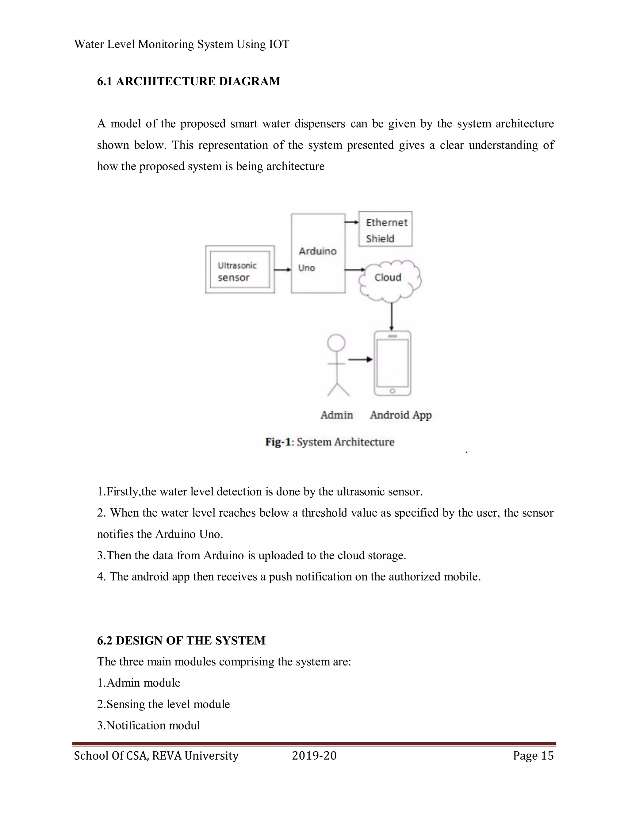
Block Diagram:
Fig 1 Block Diagram of water level monitoring system.
sensor
network
signal
conditioner
displaymicro
controller
motor
driver
motor](https://image.slidesharecdn.com/waterlevelmonitoringsystem-200521080539/75/Water-level-monitoring-system-5-2048.jpg)
![Water Level Monitoring System Using IOT
School Of CSA, REVA University 2019-20 Page 6
The proposed system uses five sensors to sense various levels of the storage. Whenever the
water level rises or decreases and comes in contact of any sensor then the circuit is complete
and current flows due to which the corresponding transistor conducts and circuit is closed.
The output of the sensor circuit triggers the microcontroller. Whenever the water level rises
above the highest level or decreases below the lowest threshold level then the sensor circuit
triggers the microcontroller. According to the code written and burnt in the microcontroller,
it will drive the DC motor. The motor driver is provided to drive and control the motor. An
LCD is provided to inform the user about the status of the water level in the tank .
LCD modules are very commonly used in most embedded projects, the reason being its
cheap price, availability and programmer friendly. There are a lot of combinations available
like, 8×1, 8×2, 10×2, 16×1, etc. but the most used one is the 16×2 LCD. 16×2 LCD is
named so because; it has 16 Columns and 2 Rows. It will have (16×2=32) 32 characters in
total and each character will be made of 5×8 Pixel Dots. Each character has (5×8=40) 40
Pixels and for 32 characters we will have (32×40) 1280 Pixels. Further, the LCD should also
be instructed about the Position of the Pixels. Hence it will be a hectic task to handle
everything with the help of MCU, hence an Interface IC like HD44780 is used, which is
mounted on the backside of the LCD Module itself. The function of this IC is to get the
Commands and Data from the MCU and process them to display meaningful information
onto our LCD Screen.
Arduino Uno
Arduino is an open source computer hardware and software company, project, and user
community that designs and manufactures single-board microcontrollers and
microcontroller kits for building digital devices and interactive objects that can sense and
control objects in the physical and digital world. The UNO is the best board to get started
with electronics and coding. The UNO is the most used and documented board of the whole
Arduino family. Arduino Uno is a microcontroller board based on the ATmega328 [4]. It
has 14 digital input/output pins (of which 6 can be used as PWM outputs), 6 analog inputs, a
16 MHz quartz crystal, a USB connection, a power jack, an ICSP header and a reset button.
It contains everything needed to support the microcontroller; simply connect it to a](https://image.slidesharecdn.com/waterlevelmonitoringsystem-200521080539/75/Water-level-monitoring-system-6-2048.jpg)


The document outlines a water level monitoring system designed to address water wastage and improve efficiency through IoT and embedded systems. It explains the system architecture, benefits of automation, potential drawbacks of existing systems, and the proposed solution involving sensors and user notifications via a mobile application. The system promises advantages such as reduced manpower, continuous water supply management, and operational automation, while also noting challenges related to sensor reliance and cost.


![1. SIH2025-IDEA-Presentation-Format[1].pptx](https://cdn.slidesharecdn.com/ss_thumbnails/1-251204091914-b1bb69d5-thumbnail.jpg?width=640&height=640&fit=bounds)