SlideShare a Scribd company logo
1 of 54
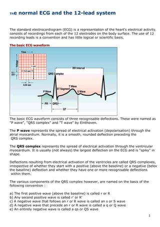
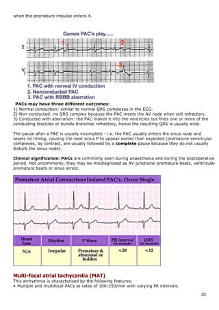
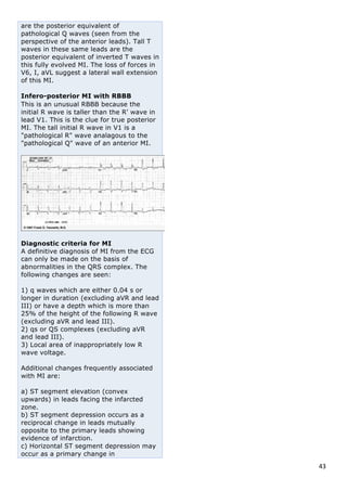
Download to read offline
1	
The normal ECG and the 12-lead system


The standard electrocardiogram (ECG) is a representation of the heart's electrical activity. It
consists of recordings from each of the 12 electrodes on the body surface. The use of 12
recording leads is a convention and has little logical or scientific basis.
The basic ECG waveform


The basic ECG waveform consists of three recognisable deflections. These were named as
"P wave", "QRS complex" and "T wave" by Einthoven.
The P wave represents the spread of electrical activation (depolarisation) through the
atrial myocardium. Normally, it is a smooth, rounded deflection preceding the
QRS complex.
The QRS complex represents the spread of electrical activation through the ventricular
myocardium. It is usually (not always) the largest deflection on the ECG and is "spiky" in
shape.
Deflections resulting from electrical activation of the ventricles are called QRS complexes,
irrespective of whether they start with a positive (above the baseline) or a negative (below
the baseline) deflection and whether they have one or more recognisable deflections
within them.
The various components of the QRS complex however, are named on the basis of the
following convention :
a) The first positive wave (above the baseline) is called r or R
b) Any second positive wave is called r' or R'
c) A negative wave that follows an r or R wave is called an s or S wave
d) A negative wave that precede an r or R wave is called a q or Q wave
e) An entirely negative wave is called a qs or QS wave
2	
f) LARGE DEFLECTIONS are named with an appropriate CAPITAL letter and
small waves with an appropriate small (lower case) letter.
The T wave represents electrical recovery (repolarisation) of the ventricular myocardium.
It is a broad, rounded wave following the QRS complex.
The U wave may be due to slow replolarisation of the papillary muscles. Some causes
include: Bradycardia, hypokalaemia and digoxin.


The standard limb
leads/bipolar limb leads (leads I, II, III) 

With the bipolar system, one limb is connected
to the positive terminal of the recording galvanometer and another limb to its negative terminal.
Three limbs (right arm-RA, left arm-LA and left leg/foot-LL) are used. The right leg was used as
"earth", to minimise interference.
We have the following bipolar leads:
Lead I: RA (-) to LA (+)
Lead II: RA (-) to LL (+)
Lead III: LA (-) to LL (+)
Augmented/unipolar limb leads (frontal plane)
Initially, unipolar limb leads were used, in which recordings were made from the RA (lead R),
LA (lead L) and LL (lead F for "foot").
Any voltage measurement requires two electrodes: a "reference electrode", whose potential
does not change during the cardiac cycle, and an "exploring electrode" attached to the limb in
question. A voltage or "V" lead was used as an indifferent electrode by joining R, L and F together.
Nowadays, the limb connections are slightly modified, to "augment" the size of the deflections
3	
obtained from leads L, R and F. These are named as follows:
aVR: RA (+) to [LA & LL] (-)
aVL: LA (+) to [RA & LL] (-)
aVF: LL (+) to [RA & LA] (-)
The precordial/chest leads (horizontal plane)
With each precordial lead, the positive (recording) terminal of the galvanometer is connected to
an electrode at an agreed site on the chest wall, and the negative terminal is connected to an
indifferent electrode, the"V" electrode (see above).
Hence, the chest leads are designated as V1, V2, V3, V4, V5 and V6.
The sites of the above electrodes are as follows:
V1: Right sternal margin at 4th intercostal space (ICS)
V2: Left sternal margin at 4th ICS
V4: Intersection of 5th ICS and left mid-clavicular line
V3: midway between V2 and V4
V5: Intersection of left anterior axillary line with a horizontal line through V4
V6: Intersection of left mid-axillary line with a horizontal line through V4 and V5
Einthoven's triangle hypothesis
Published in 1913, this hypothesis attempts to explain the principles of electrocardiography on a
scientific basis. It is based on four assumptions which are not completely true, but do provide
some basis. The four assumptions are as follows:
1. The trunk is a homogeneous volume conductor.
2. The mean of all the electrical forces generated during the cardiac cycle can be considered as
originating from a dipole situated at the heart’s centre.
3. The limb leads pick up voltage changes in the frontal plane only.
4. The attachments of the three extremities used in making the limb leads (R, L and F) form the
apices of an equilateral triangle with the dipole at its centre.
Determination of the electrical axis
The electrical axis of the heart can be derived from the six frontal plane, and leads to an accuracy
of +/- 15°. The axis is measured by reference to the hexaxial reference system (see figure above).


Calculation of the axis requires determining the algebraic sum of the QRS deflections in each
limb lead. This is done by adding the positive deflections and subtracting the negative
deflections of the QRS complex in any given lead.
Follow these steps for calculating the QRS axis:
1. By inspection, find the frontal-plane lead in which the algebraic sum of the QRS complex
2. deflections most closely approximates to zero (not necessarily the smallest QRS complex!).
The axis will be approximately at right angles to this lead and must therefore lie in
one of two approximate directions. 

For example, if the algebraic sum of the QRS complex deflections most closely approximates
zero in lead I, then the axis must lie approximately at either -90° or +90°, which are the two
directions perpendicular to lead I.
3. Now examine the QRS complex in that limb lead which occupies a position at right angles to
4. the original lead (where the algebraic sum of the QRS deflections was close to zero) - i.e. in
lead aVF.
4	
If the QRS complex deflection in this lead is dominantly positive, then the QRS axis should
be +90° (direction of aVF). But if predominantly negative, then the QRS axis will be -90°.
The above calculation gives accuracy to the nearest 30°. However, resolution to the
nearest 15° can be obtained by further adjustments (not discussed here).
Examples are as follows:
(1) Normal axis:
• Lead aVF is the isoelectric lead.
• The two perpendiculars to aVF are 0° and 180°.
• Lead I is positive (i.e. orientated to the left).
• Therefore, the axis has to be 0°.
(2) Axis in the left axis deviation (LAD) range:
5	
• Lead aVR is the smallest and isoelectric lead.
• The two perpendiculars are -60° and +120°.
• Leads II and III are mostly negative (i.e. moving away from the + left leg)
• The axis, therefore, is -60°.
(3) Axis in the right axis deviation (RAD) range:
6	


• Lead aVR is closest to being isoelectric (slightly more positive than negative)
• The two perpendiculars are -60° and +120°.
• Lead I is mostly negative; lead III is mostly positive.
• Therefore, the axis is close to +120°. Because aVR is slightly more positive, the axis is slightly
beyond +120° (i.e. closer to the positive right arm for aVR).
Normal appearances in precordial leads


P waves: Upright in V4-V6.
Upright or biphasic in V1-V2 (negative component should be smaller if biphasic)
QRS complexes:
(1) Morphology: V1 shows an rS pattern
V6 shows a qR pattern
The size of the r wave increases progressively from V1 to V6
Transition zone: the initial part of the QRS deflection is positive in the right precordial leads.
The transition zone is the point between V1 and V6, where the initial deflection ceases to be
positive and becomes negative.
7	
To the left of this point of transition, the dominant deflection is positive, and to the right of this,
it is negative. When this zone is between V3 and V4, the heart is intermediate in position
(neither clockwise nor counter-clockwise rotated). However, when the transition zone is
between V2 and V3/V1 and V2, there is counter-clockwise cardiac rotation and when the
transition zone is between V4 and V5/V5 and V6, there is clockwise cardiac rotation.
(2) Dimensions:
• QRS duration < 0.12 s
• At least one R wave in the precordial leads must exceed 8 mm
• The tallest R wave in the precordial leads must not exceed 27 mm
• The deepest S wave in the precordial leads must not exceed 30 mm
• The sum of the tallest R wave in the left precordial leads and the deepest S wave in the right
precordial leads must not exceed 40 mm
• Precordial q waves must not equal/exceed 0.04 s in duration
• Precordial q waves must never have a depth greater than one quarter of the height of the
• R wave which follows them.
ST segments: Must not deviate above or below the isoelectric line by more than 1 mm.
Normal ST segment elevation occurs in leads with large S waves (e.g. V1-3), and the normal
configuration is concave upward.
T waves: Upright in V4-V6.
Often inverted in V1, may be inverted in V2 (provided already inverted in V1).
The T wave height should not be more than two-thirds and not less than one-eighth of the
height of the preceding R wave in any of the leads V3-V6.
Normal appearances in limb leads
8	
P waves: Best seen in lead II (Small rounded waves)
• P wave height = 2.5 mm
• P wave duration = 0.12 s
QRS complexes: Mean frontal plane QRS axis range is between +90°and -30 °; this implies
that the QRS is mostly positive (upright) in leads I and II.
R wave in aVL must not exceed 13 mm and R wave in aVF must not exceed 20 mm.
Normal q waves reflect normal septal activation (beginning on the LV septum); they are narrow
(<0.04 s duration) and small (<25% the amplitude of the following R wave). They are often
seen in leads I and aVL when the QRS axis is to the left of +60°, and in leads II, III, aVF when
the QRS axis is to the right of +60°. Septal q waves should not be confused with the pathological
Q waves of myocardial infarction.
ST segments: Must not deviate above or below the isoelectric line by more than 1mm.
T waves: In the normal ECG, the T wave is always upright in leads I, II, V3-6, and always
inverted in lead aVR.
The U wave:
• U wave amplitude is usually < one-third T wave amplitude in same lead.
• U wave direction is the same as T wave direction in that lead.
U waves are more prominent at slow heart rates and usually best seen in the right precordial
leads.
The normal rhythm of the heart
The heart is said to be in sinus rhythm based on the following criteria: 

• P waves must be present and be regular.
• P wave frequency should be within the range of 60-100 per min.
• There must be one P wave for each QRS complex.
• The P wave must precede each QRS complex.
• The PR interval must be normal and constant.
• The morphology of the P waves and QRS complexes must be the usual form for that patient.
9	
Electrophysiology of the heart
	
	
The myocardium can conduct an electrical impulse in any direction. The actual direction of
spread will thus depend on where the activation was initiated. Conduction must occur in all
directions from this point. But the predominant direction of spread will be in that direction in which
the greatest mass of myocardium is available from the point of initiation.
The sino-atrial or SA node is situated in the right atrium at its junction with the superior vena cava.
Normally, the SA node initiates activation of the atria, which causes a wave of contraction to pass
across the atria. Following atrial contraction, the impulse is delayed at the atrioventricular (AV)
node, located in the septal wall of the right atrium.
Spread of electrical activation
1) Activation of the atrial myocardium begins in the SA node. The radial spread of depolarisation
2) then converges on the AV node, where there is a delay for about 0.1 seconds (AV nodal
delay).
From here, His-Purkinje fibres allow rapid conduction of the electrical impulse via right and left
branches, causing almost simultaneous depolarisation of both ventricles, approximately 0.2 s
after
the initial impulse has arisen in the SA node.
3) In humans, the ventricular depolarisation starts at the left side of the interventricular septum
and moves first to the right across the mid-portion of the septum.
4) It then spreads down the septum to the apex of the heart.
5) It then returns along the ventricular walls to the AV groove, proceeding from the endocardial
to the epicardial surface.
6) The last parts of the heart to be depolarised are the posterobasal portion of the left ventricle, the
pulmonary conus and the uppermost portion of the interventricular septum.
The predominant direction of spread of atrial activation is to the left and somewhat downwards.
The predominant direction of spread of ventricular activation is downwards and somewhat to the
left.
10	
ArticleDate:20060811


systematic approach to ECG interpretation
	
Like the physical examination, it is desirable to follow a standardised sequence of steps in order
to avoid missing subtle abnormalities in the ECG tracing, some of which may have clinical
importance. The following order may be helpful:
1-Documentation: Any ECG record should include the name of the patient and the date and
time it was recorded.
2 -Calibration signal: The amplifier gain is normally adjusted so that a 1 millivolt
signal through
the ECG amplifier results in a vertical deflection of 10 mm (two large ECG squares). All voltage
measurements on the ECG depend entirely on the accuracy of this calibration signal. (The paper spe
amounts to 0.04 s per small box on the horizontal axis).
3 -Recording quality: Look for any baseline drift (which makes ST segment analysis
impossible), skeletal muscle interference (seen as sharp, irregular, spiky waves throughout
the recording - e.g. during shivering) or mains frequency interference (seen as regular sine wave
frequency of 50 Hz).
4) Measurements:
a) Heart rate: Can be calculated easily from the ECG paper itself.
Because ECG paper moves at a standardised 25 mm/s, the vertical lines can be used to measure
time. There is a 0.20 s interval between two of the large lines. Therefore, if you count the
number of heart beats (QRS complexes) in between 30 large boxes (6 s) and multiply by 10,
11	
you have beats per minute. Conveniently, ECG paper usually has special markings every 3 s,
so you do not have to count 30 large boxes.
There is, however, an easier and quicker way to estimate the heart rate. As seen in the diagram
below, when QRS complexes are one box apart, the rate is 300 bpm. Two boxes apart...
150 bpm, etc. So if you memorise these simple numbers, you can estimate the heart rate at
a glance!
Rule of 300 - Provided that the rhythm is regular, heart rate can be estimated by dividing
300 by the number of large boxes in the R-R interval.
i.e. Heart Rate = 300/ no. of large boxes in the R-R interval
If the rhythm is irregular, a longer ECG strip should be obtained and the number of QRS
complexes on a strip of determined duration must be counted.
If the number of QRS complexes on a strip of 60 large squares (which is the number of
complexes in 12 s, because each large square is 0.2 s in duration) is multiplied by 5,
then the rate per minute is deduced.
b) PR interval: 0.12 - 0.20 s
c) QRS duration: 0.06 - 0.10 s
d) Corrected QT interval (QTc): normal QTc = 0.40 s
12	
Bazett's formula: QTc = QT / RR1/2
(in seconds)
e) Frontal plane QRS Axis: +90° to -30° (in the adult)
5) Rhythm: Normal sinus rhythm or any abnormalities present
6) Morphological information: gives information about the physical condition of the heart.
This information is contained in the P waves, QRS complexes, ST segments and T waves.
The waves should be studied in both the limb and precordial leads, as discussed above.
7) Comparison with previous ECG: The present ECG should be compared with any previous
ones in the patient’s notes, to see if any significant changes have occurred. These changes may
have important implications for clinical management decisions.
Note: Horizontal and vertical heart:
(1) Mean frontal plane QRS axis is between 0° to -30°: heart is said to be horizontal
(2) Mean frontal plane QRS axis is between +60° to +90°, the heart is said to be vertical.
Conduction abnormalities
ArticleDate:20060828
Sinus node block
This involves failure of the sinus node to depolarise or failure of impulse conduction from the sinus
node to the atria.
It may be seen during anaesthesia (due to vagal reflexes); during drug therapy with digoxin,
quinidine or phenylephrine; myocardial ischaemia or infarction; and due to ischaemia-induced
fibrosis of the sinus node.
ECG changes: An absent P wave and often an absent QRS complex are seen.
Manifested by a gradual shortening of the P-P intervals until a pause occurs (i.e. the blocked sinus
impulse fails to reach the atria).
13	
Sick sinus syndrome is a term used for a number of disorders that involve degenerative
changes in the cardiac conduction system, resulting in sinus node dysfunction and, possibly,
AV blocks too. Causes include myocardial ischaemia or infarction, hypertension, electrolyte and
endocrine abnormalities, cardiomyopathies, inflammatory diseases and drug effects.
Atrioventricular (AV) blocks
Possible sites of AV block include:
• AV node (most common).
• His bundle (uncommon).
• Bundle branch and fascicular divisions.
1st degree AV block: This may be seen in healthy individuals
Features include:
• Prolonged PR interval - i.e. PR interval >0.20 s.
• All P waves are conducted to the ventricles.
2nd degree AV block: All of the atrial impulses are not conducted to the ventricles.
There may be, for example, a ventricular beat following every second or every third atrial beat
(2:1 block, 3:1 block etc.).
2nd degree AV block is subdivided into two classes as follows:
(a) Mobitz Type I (Wenckebach phenomenon)
The PR interval lengthens gradually until a P wave which fails to conduct to the ventricles occurs.
The block in this case is almost always located in the AV node and may be caused by right coronary
artery occlusion causing inferior wall infarctions.
14	
(b) Mobitz Type II
This involves an intermittent block in conduction of the P wave into the ventricles, but the PR interva
in surrounding beats is unaltered. Type II AV block is almost always located in the bundle branches.
Type II block may result from anterior wall infarctions. These blocks are generally permanent, with a
greater risk of progressing to complete heart block.
3rd degree /complete heart block: This involves total disruption of conduction between
the atria and ventricles. In this situation, life is maintained by a spontaneous escape rhythm.
In 'A', the ECG shows complete or 3rd degree AV block with a left ventricular escape rhythm, as
evidenced by the upright QRS morphology. In 'B', the artificial right ventricular pacemaker
rhythm is shown.
Narrow complex escape rhythm (<0.12s QRS complex): The escape rhythm originates in
the His bundle and therefore the site of block lies more proximally in the AV node. The escape
rhythm occurs at a rate of 50-60 bpm and is relatively reliable.
15	
Treatment depends on aetiology. But chronic symptomatic blockade requires permanent pacing.
Broad complex escape rhythm (>0.12s QRS complex): The escape rhythm originates
below the His bundle and therefore the site of blockade lies more distally in the
His-Purkinje system. The resulting rhythm is slow (15-40 bpm) and unreliable. Dizziness and
blackouts (Stoke-Adams attacks) often occur. Temporary followed by permanent pacing may be
required.
Intraventricular blocks
Right bundle branch block (RBBB)
This involves:
• Total failure of conduction in the right bundle branch proximally.
• No change in the direction of depolarisation of the interventricular septum.
• No change in the timing or direction of left ventricular depolarisation.


Diagnostic criteria for RBBB: 

1) "Complete" RBBB has a QRS duration >0.12 s.
2) A secondary R wave is seen in V1. The secondary wave is usually broad and slurred #
(the complex in V1 may be rsr’, rSr’, RSr’, RSR’ or M-shaped).


Additional features frequently seen in RBBB include: 
1) Deep, slurred S waves in
left precordial leads (typically V4,V5,V6).
2) Deep, slurred S waves usually seen in lead I and also aVL.
3) ST segment depression and T wave inversion are seen in the right precordial leads
(typically in leads V1, V2, V3). This occurs due to secondary changes in ventricular
repolarisation (ST segment and T waves).
The mean frontal plane QRS axis is usually within the normal range in uncomplicated
16	
complete RBBB. The axis may move 15-30° towards the right, but abnormal right axis deviation is
not a routine feature of RBBB. If left axis deviation is present, think about left anterior fascicular
block, and if right axis deviation is present, think about left posterior fascicular block in
addition to the RBBB.
Clinical significance: 
RBBB may occur congenitally in normal hearts. It can be seen in
a variety of disorders, including ischaemic heart disease, hypertension, pulmonary embolism,
cardiomyopathy, myocarditis, pericarditis, rheumatic heart disease, Chagas disease and
congenitally in association with atrial septal defect and Fallot’s tetralogy.
Left bundle branch block (LBBB) 

This involves:
• Total failure of conduction in the left bundle branch system.
• Complete reversal of the direction of depolarisation of the interventricular septum.
• Delay in the initiation and velocity of depolarisation of the free wall of the left ventricle.


Diagnostic criteria for LBBB:
1) Total QRS duration >0.12 s.
2) No secondary R wave in V1 to indicate RBBB.
3) No septal q wave in V5, V6 or in leads further to the left (lead I and aVL in horizontal hearts).


Additional features frequently seen in LBBB include:
17	
1) The QRS complexes in some leads may be notched (leads I, aVL, V5 and V6).
2) The QRS complexes in V5, V6, I and aVL tend to have rsR’, "M" pattern or broad monophasic R
waves.
3) Secondary ST depression and possibly T wave inversion may be seen in the left precordial leads
(and in leads I and aVL).
4) ST segment elevation and abnormally tall T waves may be seen in the right precordial leads.
5) Abnormally deep S waves in the right precordial leads.
6) Initial r waves in the right precordial leads may be very small or absent.
7) In the precordial leads, the dominant direction of the ST segments and the T waves tends to be
opposite to the dominant direction of the QRS complexes in any given lead.
The mean frontal plane QRS axis is usually within the normal range in uncomplicated
complete LBBB. The axis may move 15-30° towards the left when LBBB develops but abnormal
left axis deviation is not a routine feature of LBBB. The axis may sometimes be indeterminate.
When LBBB is combined with abnormal left axis deviation, extensive disease of the left ventricular
conducting system is likely to be present.
Incomplete LBBB is diagnosed when: 

1) There is no septal q wave in V5, V6 or in leads further to the left (leads I and aVL) and
2) The total QRS duration is 0.10-0.11 s.
Clinical significance: 

LBBB always indicates significant cardiac disease. It is seen most commonly in ischaemic heart
disease, hypertension, aortic stenosis and fibrous degeneration of the conducting tissue.
It may also occur in congestive and hypertrophic cardiomyopathy, myocarditis, acute rheumatic
fever, syphilis, cardiac tumours, post-cardiac surgery and in congenital heart disease.
Fascicular blocks
According to this concept, there are three fascicles of conduction:
1) Right bundle branch
2) Anterior division of the left bundle branch and
3) Posterior division of the left bundle branch.
We shall now consider unifascicular blocks of the divisions of the left bundle branch –
i.e. left anterior hemiblock and left posterior hemiblock.
Normally, the left ventricle is depolarised simultaneously from two directions:
a) A depolarisation wave spreading from below upwards and to the left as a result of transmission
through the posterior (inferior) division and
b) A depolarisation wave spreading from above downwards and to the left as a result
of transmission through the anterior (superior) division.
Left anterior fascicular block (LAFB): 

In this abnormality, the antero-superior division of the left bundle totally fails to conduct.
Hence, the antero-superior part of the left ventricle (LV) is activated in the opposite direction
by the depolarisation wave after it emerges from the postero-inferior part of the LV, which receives
the wave in a normal manner through the posterior (inferior) division of the left bundle.
Diagnostic criteria for LAFB are: 

1) Left axis deviation with QRS axis more negative than -30°.
2) Initial r waves in all inferior limb leads (leads II, III, aVF).
18	
3) Other recognised causes of left axis deviation must be absent**.
Additional features frequently seen in LAFB include: 

Total QRS duration is usually at the upper limit of normal (0.09-0.10 s)
Other causes of abnormal left axis deviation include:
• Ventricular pre-excitations - e.g. Wolff-Parkinson-White syndrome.
• Inferior myocardial infarction.
• Tricuspid atresia and ostium primum atrial septal defect.
• Hyperkalaemia.
Clinical significance:
Chronic LAFB may be a normal finding in the elderly without evidence of heart disease. It may be
present after acute myocardial ischaemia, hypertension, congestive and hypertrophic
cardiomyopathy, myocarditis, calcific aortic stenosis and following aortic valve replacement.
Important differential diagnosis of LAFB
Abnormal left axis deviation is the most striking feature of LAFB. The second most common
cause of an abnormal left axis deviation is an inferior myocardial infarction. 

The important difference in the ECG between the above two conditions is the presence of:
• initial r waves in all inferior limb leads (II, III, aVF) in LAFB
BUT
• there are abnormal Q waves in the inferior leads in inferior myocardial infarction.
Left posterior fascicular block (LPFB): 

This occurs less frequently than an LAFB.
This is because the posterior division of the left bundle is thicker and shorter and has a
much better blood supply than its counterpart.
In this abnormality, the postero-inferior division of the left bundle fails to conduct. Hence, the
postero-inferior part of the LV is activated in the opposite direction by the depolarisation wave after i
emerges from the antero-superior part of the LV, which receives the depolarisation wave
in a normal manner through the antero-superior division of the left bundle.
In left posterior fascicular block, the only ECG features seen are: 

1) A mild degree of right
axis deviation (between +90° and +120°) and
2) Total QRS duration is at the upper end of normal (0.09-0.10 s).
Due to only subtle changes brought about by a left posterior fascicular block on the ECG, it is
impossible to be sure about a LPFB from the ECG alone. Other possible causes of right axis
deviation should be excluded (e.g. emphysema, right ventricular hypertrophy, atrial septal
defect and an extensive antero-lateral myocardial infarction).
Bifascicular blocks: 

19	
When two fascicles are blocked simultaneously, a bifascicular block is said to exist.
This includes the more common combination of right bundle branch block (RBBB)
with left anterior fascicular block (manifest as LAD), and the less common RBBB with
left posterior fascicular block.
Trifascicular block:

This is a combination of bifascicular block and 1st
degree heart block.
Diagnostic criteria for RBBB with left anterior fascicular block are: 

1) Total QRS duration = 0.12 s.
2) A secondary R wave in V1.
3) Mean QRS axis is more negative than -30°.
4) An initial r wave is seen in the inferior limb leads (II,III and aVF).
In RBBB with left posterior fascicular block, the ECG features are: 

1) Total QRS duration = 0.12 s.
2) A secondary R wave in V1.
3) Mean QRS axis is more positive than +90°.
Clinical significance: 

RBBB with LAFB is more common. But both of the above bifascicular blocks can occur in similar
conditions. This includes conditions like atherosclerotic heart disease, calcific aortic stenosis,
hypertrophic and congestive cardiomyopathy, and congenital endocardial cushion defects.
Although an RBBB with LPFB is less common, 60-70% of those that do occur progress to a
complete heart block.


SUPRAVENTRICULAR	ARRYTHMIA	
	
	
Premature atrial complexes (PACs)
These may occur as single or repetitive events and may be unifocal or multifocal in origin. The
premature P wave (P’ wave) differs in contour from the normal sinus wave, which is usually
followed by a normal QRST sequence.
The P'R interval is normal or prolonged because the AV junction is often partially refractory
20	
when the premature impulse enters it.

PACs may have three different outcomes: 

1) Normal conduction: similar to normal QRS complexes in the ECG.
2) Non-conducted: no QRS complex because the PAC meets the AV node when still refractory.
3) Conducted with aberration: the PAC makes it into the ventricles but finds one or more of the
conducting fascicles or bundle branches refractory, hence the resulting QRS is usually wide.
The pause after a PAC is usually incomplete - i.e. the PAC usually enters the sinus node and
resets its timing, causing the next sinus P to appear earlier than expected (premature ventricular
complexes, by contrast, are usually followed by a complete pause because they do not usually
disturb the sinus node).
Clinical significance: PACs are commonly seen during anaesthesia and during the postoperative
period. Not uncommonly, they may be misdiagnosed as AV junctional premature beats, ventricular
premature beats or sinus arrest.
Multi-focal atrial tachycardia (MAT)
This arrhythmia is characterised by the following features:
• Multiple and multifocal PACs at rates of 100-250/min with varying PR intervals.
21	
• Ventricular response is irregularly irregular (rate of 100-200/min).
• MAT may be intermittent, alternating with periods of normal sinus rhythm


Clinical significance: 

1) MAT indicates diffuse atrial disease, including atrial distension
with/without sinus node degeneration.
2) Seen commonly in association with advanced chronic obstructive pulmonary disease.
3) MAT may cause significant haemodynamic compromise due to impaired atrial and ventricular
filling.
4) The rhythm usually returns to normal once the underlying acute medical problem subsides.
Atrial flutter
The ECG features of atrial flutter are:
1) An atrial rate between 250-350 bpm
2) A saw-tooth appearance (F waves) is seen in leads II, III, aVF and V1.
Variable degrees of AV block is seen (2:1 being more common).
22	


Clinical significance: 

1) Atrial flutter usually results from a re-entrant circuit located totally within the atrial wall.
2) It is generally associated with heart disease - e.g. rheumatic heart disease (with mitral stenosis).
3) 1:1 ventricular conduction may compromise cardiac output significantly.
4) Haemodynamic compromise may warrant electrical cardioversion.
5) Digitalis is very effective in slowing ventricular rate, while ß-blockers or verapamil slow the
ventricular rate and sometimes revert it to sinus rhythm.
Atrial fibrillation (AF)
The ECG features of atrial fibrillation include:
• Rapid, irregular fibrillating atrial waves (f waves) at a rate of 300-600 bpm, best seen in leads II,
III, aVF and V1. The fibrillation is probably caused by numerous microentry circuits
• within the atrial muscle.
• Ventricular rate is irregularly irregular, with a rate of 140-200 bpm due to a certain degree of AV
block which is always present.
• The differential diagnosis includes atrial flutter with an irregular ventricular response and
• multi-focal atrial tachycardia, which is usually irregularly irregular.
•
•
23	
•
Clinical significance:
• AF is usually associated with chronic heart disease (valvular, myocardial or pericardial).
• Also seen in hyperthyroidism, pulmonary embolism and chronic lung disease.
• Electrical cardioversion may be required in the acute setting with haemodynamic compromise.
Paroxysmal supraventricular tachycardia (PSVT)
These arrhythmias occur due to circus movements, thus utilising the mechanism of reentry. The
onset and resolution are sudden and usually initiated by a premature beat, thus the term
"paroxysmal". They are generally narrow-QRS tachycardias (unless there is pre-existing bundle
branch block or aberrant ventricular conduction). There are several types of PSVT,
depending on the location of the reentry circuit.
AV nodal reentrant tachycardia (AVNRT)

This is the most common form of PSVT
accounting for approximately 50% of all symptomatic PSVTs. It is the most common cause
of SVT in patients with structurally normal hearts.
It is accompanied by the following features:
1) ECG shows normal regular QRS complexes with a rate of 140-240 bpm.
2) QRS complexes may sometimes show typical bundle branch block/aberration.
3) P waves are either not visible or are seen immediately before or after the QRS complex.
4) An attack may be spontaneously triggered but exertion, tea, coffee or alcohol may trigger an
AVNRT.
5) Vagal manoeuvres may terminate an acute attack.
6) Beta-blockers or calcium channel blockers may help to suppress recurrent attacks.
The diagram illustrates the probable mechanism involving dual AV nodal pathways, alpha and
beta, with different electrical properties. In the diagram, alpha is a fast AV nodal pathway with
a long refractory period (RP), and beta is the slow pathway with a short RP. During sinus rhythm,
alpha is always used because it conducts faster. An early PAC, however, finds alpha still refractory
and must use the slower beta pathway to reach the ventricles. By the time it traverses beta,
however, alpha has recovered, allowing retrograde conduction back to the atria. The retrograde P
wave (called an atrial echo, for obvious reasons) is often simultaneous with the QRS and,
therefore, not seen on the ECG, but it can re-enter the AV junction because of beta's short RP.
24	
AV reciprocating tachycardia (extranodal bypass pathway)

This is the second most
common form of PSVT and is seen in patients with Wolff-Parkinson-White (WPW) syndrome. The
WPW ECG, seen in the diagram, shows a short PR, delta wave and a somewhat widened QRS.
25	


Junctional arrhythmias
	
Junctional rhythm
This occurs when the sinus rate is slowed or when the junctional pacemaker increases its firing rate.
The normal junctional pacemaker discharge rate is 40-60 bpm. Depending upon whether the
conduction from the junctional pacemaker is anterograde or retrograde, inverted "P" waves (inferior
leads) may be seen preceding, following or coinciding with the QRS complex.
The QRS complex will be identical to that resulting from normal sinus conduction because the origin o
firing is above the bundle branch divisions.


26	
x
Clinical significance: 

Junctional rhythms occur commonly under anaesthesia, especially using halogenated agents.
This may cause a fall in cardiac output and blood pressure, and may need treatment with an anti-
cholinergic agent or vasopressor.
AV nodal tachycardia
This is manifested as a:
• Passive escape rhythm with a rate of 70-140 bpm, or as a
• Paroxysmal junctional tachycardia with a rate of 150-200 bpm
• The P waves may occur before, within or after the QRS complexes, or be unrelated to it.
• The QRS complex is usually narrow (may be wide with a bundle branch block).
Clinical significance:
This arrhythmia is relatively common under halothane anaesthesia. It rarely requires treatment.
In patients receiving digitalis, this arrhythmia may represent digitalis toxicity.
27	
	
	
Ventricular arrhythmias
	
Premature ventricular complexes (PVCs)
A premature ventricular contraction is an impulse that originates prematurely in the ventricles and
perturbs the prevailing rhythm. The mechanism of PVCs may be either increased automaticity of
ventricular foci or reentry.
ECG shows a premature wide, slurred, bizarre QRS complex followed by a T wave, usually in the
opposite direction to the main QRS deflection. PVCs are usually followed by full compensatory
pauses.
28	


The events following a PVC are of interest. Usually, a PVC is followed by a complete compensatory
pause because the sinus node timing is not interrupted; a sinus P wave is unable to reach the
ventricles because they are still refractory from the PVC; the following sinus impulse occurs on
time, the time course being dependent on the sinus rate. By contrast, PACs are usually followed by
an incomplete pause because the PAC usually enters the sinus node and resets its timing; this enable
the following sinus P wave to appear earlier than expected. These concepts are illustrated below.
29	

Ventricular bigeminy is said to occur when PVCs alternate with the normal beat. Causes may
include electrolyte abnormalities, stimulants and digoxin toxicity.
Multifocal PVCs are characterised by at least two abnormal QRS complexes of different
configurations. Certain types of PVCs are potentially dangerous because they may deteriorate into a
ventricular tachycardia. This is particularly true when PVCs occur in couplets or triplets, are multi-foc
or there is an "R-on-T phenomenon" (when the R wave of the PVC falls on the T wave of the previous
beat).
30	
Ventricular tachycardia
This is defined as episodes of four or more consecutive PVCs. It arises in the specialised conduction
system distal to the bundle of His bifurcation, the mechanism of VT being abnormal automaticity or
reentry.
The ECG in VT shows a uniform series of widened QRS complexes, usually regular with
a rate ranging from 70-250 bpm. The hallmark of VT is AV dissociation.
It is important to distinguish VT from a supraventricular tachycardia (SVT) with aberrant
conduction. VT is diagnosed by the presence of fusion and capture beats, AV dissociation,
left axis deviation and compensatory pauses.
By contrast, an SVT with aberrant conduction is characterised by the presence of P waves
preceding the QRS complexes, the onset of the dysrhythmia with a premature P wave, an RSR’
pattern
31	
in V1 and slowing/termination of the dysrhythmia by vagal stimulation.
Synchronous cardioversion is often required to treat VT failing, which may deteriorate into VF.
Torsade de pointes
This is VT with a varying axis and is caused by anything that prolongs the QT. Treatment is with
magnesium sulphate 8mmol (4ml of 50%), or overdrive pacing.
Ventricular fibrillation (VF)
Ventricular fibrillation is an irregular rhythm resulting from a rapid discharge of impulses
from one or more foci in the ventricles. The ventricular contractions are erratic and seen on
the ECG as bizarre patterns of various sizes and configurations. No P waves are seen.
Some causes of VF include myocardial ischaemia, hypoxia, hypothermia, electrocution,
electrolyte and acid-base imbalance, and drug effects.
Due to the absence of any effective cardiac output, life must be sustained by artificial means - i.e.
external cardiac massage and defibrillation is "the" treatment.


Hypertrophies
	
Ventricular hypertrophy
In general, the limb leads are less useful in diagnosing ventricular hypertrophies. Lesser degrees of
hypertrophy (especially right ventricular hypertrophy) may be present without any ECG changes or
with non-specific changes only.
The left ventricular wall thickness is about three times greater than the right ventricular free wall.
This results in the left ventricular muscle mass generating a voltage that is 10 times greater than
the right ventricular voltage. Thus, left ventricular hypertrophy (LVH) produces an exaggeration
of the normal QRS complex, whereas right ventricular hypertrophy (RVH) alters the QRS pattern
in the various ECG leads. Secondary ST-T segment and T wave changes follow the primary QRS
changes in both RVH and LVH.
Left ventricular hypertrophy (LVH)
32	
In addition to the higher voltage contribution made by the bulky left ventricle, the thicker LV wall
also results in prolongation in the time taken for the depolarisation wave to travel from
endocardium to epicardium. This time, called the "ventricular activation time" or the
"intrinsicoid deflection time" is measured from the onset of the QRS complex to the peak
of the R wave. It is measured only in left precordial leads showing a qR complex.
Criteria for left ventricular hypertrophy (LVH): 
(assuming normal calibration)
1) The R waves in any one or more of the leads V4, V5 or V6 exceeds 27 mm.
2) The tallest R wave in any of the leads V4, V5 or V6 plus the deepest S wave in any of the
leads V1, V2 or V3 exceeds 40 mm.
3) The S waves in one or more of the leads V1, V2 or V3 exceeds 30 mm.
4) The R wave in aVL exceeds 13 mm.
5) The ventricular activation time (e.g. in V6) = 0.05 s.
6) Abnormal ST segment depression (>1 mm below the isoelectric line) in any lead facing the
left ventricle (i.e. V4, V5 or V6 and in leads I and aVL when the heart is horizontal or in leads
II and aVF when the heart is vertical).
7) T wave inversion in leads facing the left ventricle (as in point 6 above).
In general, the greater the number of criteria listed above that are fulfilled, the more likely is the
diagnosis of LVH.
In this example of LVH, the precordial leads do not meet the usual voltage criteria or exhibit
significant ST segment abnormalities. The frontal plane leads, however, show voltage criteria
for LVH and significant ST segment depression in leads with tall R waves. The voltage criteria
include: 1) R in aVL >11 mm; 2) R in I + S in III >25 mm; and 3) (RI+SIII) - (RIII+SI) >17 mm
(Lewis Index).
Associated features in LVH:
1) Left ventricular complexes ("qR" complexes) may appear further to the right in the precordial
2) leads than the usual V4 –V6 - i.e. there is often counterclockwise cardiac rotation.
3) This is because of an increase in the physical size of the left ventricle, resulting in more
4) of the LV lying beneath the chest leads.
2) Usually, LVH results in a slight shift of the mean QRS axis towards the left. However, the axis
usually remains within the normal range and typically between +30° and -30°.
3) ECG evidence of left atrial hypertrophy usually accompanies that of LVH.
4) Prominent U waves are often seen in the right and mid-precordial leads.
Left ventricular "strain" patterns:
Hypertrophy of the left ventricle can occur due to conditions causing a systolic overload –
33	
e.g. aortic stenosis or conditions causing a diastolic overload, such as aortic regurgitation.
The so-called "s"ystolic overload pattern is one in which the
"S"T segment and T wave changes are relatively more prominent than the QRS changes.
Conversely, in the so-called diastolic overload pattern, the QRS changes are relatively more
prominent than the ST-T wave changes. These are ill-defined concepts and not very reliable.
Clinical significance:
Systemic hypertension is the most common cause of recognisable LVH. Other causes include aortic
stenosis, aortic incompetence, coarctation of the aorta, mitral incompetence and hypertrophic
cardiomyopathy.
Right ventricular hypertrophy (RVH)
The most obvious consequence of RVH is an increase in the voltage of the R wave in the right
precordial leads. The most diagnostic feature is a "dominant R wave" in V1. The term "dominant R
wave" (seen in V1) means that, whatever the configuration of the QRS complex in V1, the largest
wave in that QRS complex is an R wave. Thus, the most readily understood configuration of
the QRS complex in V1 is an "Rs" complex.
Unlike LVH, RVH is accompanied by deviation of the axis beyond the normal range, resulting
in right axis deviation.
Diagnostic criteria for right ventricular hypertrophy (RVH):
1) Mean QRS axis more positive than +90°.
2) Dominant R wave in V1 (Rs, R, RR’, qR or qRS).
3) Absence of evidence of anterolateral infarction.
4) QRS duration must be less than 0.12 s.
34	
Note the qR pattern in the right precordial leads. This suggests right ventricular pressures greater
than left ventricular pressures. The persistent S waves in lateral precordial leads and the right axis
deviation are other findings in RVH.
Additional features frequently present in RVH: 

	
1) ST segment depression and T wave inversion in some of the leads V1-V4.
2) Deep S waves in V5, V6 and also in leads I and aVL.
3) Evidence of right atrial hypertrophy.
Clinical significance:
RVH is predominantly caused by conditions that produce a RV systolic overload. These include
pulmonary stenosis, pulmonary hypertension and Fallot’s tetralogy. Chronic cor
pulmonale gives rise to RVH relatively rarely.
Diastolic overload of the right ventricle occurs in atrial septal defect, anomalous pulmonary venous
return and tricuspid incompetence. The ECG changes of RV diastolic overload are indistinguishable
from those in complete or incomplete RBBB.
Biventricular hypertrophy
This may be impossible to diagnose from an ECG because of the increased electrical forces, due to
RVH and LVH cancelling each other (being directed in opposite directions). If they both are enlarged
different extents, the pattern may be that of the more dominant ventricle.
Essential features of biventricular hypertrophy are:
1) It may exist without any ECG changes.
2) Total QRS duration may be prolonged to 0.10 or 0.11 s.
3) T wave inversion may be present in the precordial leads.
4) The combination of signs of LVH with an axis more positive than +90° is suggestive of
biventricular hypertrophy.
5) Occasionally, the combination of signs of RVH with an axis more negative than -30° is present.
Atrial hypertrophies
Important normality to be remembered:
a) In lead V1, the right atrial phase of depolarisation gives rise to a positive wave and the
left atrial phase gives rise to a negative wave.
This results in a biphasic P wave in V1, in which the initial part of the P wave is the right atrial
component and the latter part is due to the left atrial component.
b) In lead II, both the right and the left atrial phases of depolarisation give rise to positive waves
This results in an upright P wave in lead II.
Right atrial hypertrophy (RAH) 

In RAH, the right atrial component of the P wave is increased in both voltage and duration. This
component being a positive deflection in leads II and V1, the P wave height is increased in both
of these leads.
However, because right atrial depolarisation is normally complete well before left atrial
depolarisation is completed, the delay in completion of right atrial depolarisation is not sufficient to
prolong it beyond the end of left atrial depolarisation. Hence, the P wave duration is not
35	
increased.
Criteria for right atrial hypertrophy: 

P wave height = 3 mm in leads II, III or aVF.
An additional feature is that the positive part of the "P" wave in V1 is usually >1.5 mm in height
and there is usually also evidence of RVH.
RAH is recognised by the tall (>2.5 mm) P waves in leads II, III, aVF. RVH is likely because of
right axis deviation (+100°) and the Qr (or rSR') complexes in V1-2.
Left atrial hypertrophy (LAH)
In LAH, the left atrial component of the P wave is increased in voltage and duration. Since the
terminal part of the normal P wave is produced by left atrial depolarisation, it follows that the
total P wave duration is prolonged in LAH.
Criteria for LAH: 

Either (more likely, both) of the following criteria suggest the diagnosis:
1) The P wave is notched and exceeds 0.12 s in duration in leads I, II, aVF or aVL.
2) The P wave in V1 has a dominant negative component (i.e. either it is entirely negative or,
alternatively, the terminal negative component exceeds the initial positive component).


The P wave is notched, wider than 0.12 s and has a prominent negative (posterior)
component in V1 - all criteria for left atrial abnormality or enlargement. The PR interval is >0.20 s.
Minor ST-T wave abnormalities are also present.
Bi-atrial hypertrophy 

Even the presence of only one of the criteria listed below suggests the diagnosis:
36	
1) P waves in limb leads which are both = 3 mm in height AND >0.12 s in duration.
2) Large biphasic P wave in V1 with an initial upright portion = 2 mm in height AND a terminal
negative portion at least 1 mm deep and 0.04 s in duration.
3) Tall peaked P waves = 2 mm in height in V1 in combination with wide, notched P waves
(> 0.12 s in duration) in the limb leads or in the left precordial leads.
	
Ischaemic heart disease
The ECG is commonly used in the
investigation of suspected ischaemic heart
disease (IHD). The ECG provides
information about the myocardium and
the specialised conducting tissues that
have undergone ischaemia. It should also
be remembered that a percentage of
patients with unequivocal angina pectoris
may have normal resting 12-lead ECGs
when first seen.
The ECG in acute myocardial
infarction (MI)
Acute MI may cause changes in the QRS
complex, ST segment or the T wave.
However, the only definitive diagnostic
changes of myocardial infarction are
changes in the QRS complex.

The QRS complex in infarction
Two types of QRS abnormalities may
indicate infarction:
1) Inappropriately low R wave voltage in a
local area and
2) Abnormal Q waves
The above two abnormalities are actually
part of the same process - i.e. the
development of a negative Q wave and
the reduction in size of the positive wave.
The loss of positivity is the result of
myocardial necrosis beneath the exploring
electrode. The size of the positive wave in
each precordial lead is related to the
thickness of viable myocardium
underneath that electrode.
Abnormal Q waves and QS complexes
In a transmural infarction
(endocardium to epicardium), there will
be total loss of R waves in leads
overlying the infracted zone. This gives
rise to entirely negative waves - i.e. QS
complexes. These negative waves are
the result of depolarisation of the
37	
posterior wall of the ventricle travelling
from endocardium to epicardium (i.e.
away from the anterior leads).
The reduction in R wave voltage can only
be confirmed if either a previous ECG
shows a significantly greater R wave
height in the appropriate leads before the
infarction occurred, or the leads involved
are two or more of the leads V2 to V5.
Therefore, the four possible QRS
changes indicative of infarction are:

1) Reduced R wave voltage (confirmed
by previous ECGs)
2) Abnormal Q waves without any
conclusive evidence of R wave reduction
3) Reduced R wave voltage in association
with abnormal Q waves and
4) QS complexes.
These four changes represent increasing
thickness of infarction as part of a
common process. A combination of these
findings is seen in an infarction of non-
uniform thickness.
Abnormal Q waves
Q waves may be recognised to be
abnormal because of:
1) Abnormal width (duration) - i.e. Q
wave = 0.04 s or
2) Abnormal depth (relative to the
following R wave) - i.e. depth of Q wave
>25% of the height of the following R
wave is abnormal.
ST segment changes in myocardial
infarction 

Dramatic ST segment
changes occur in the early stages of
myocardial infarction. Such changes
indicate myocardial injury rather than
infarction.
The injury state is unstable, and acute ST
segment elevation always resolves to
some extent and usually resolves
completely. The resolution of the acute ST
elevation is usually accompanied by
development of the QRS changes of frank
infarction, although occasionally, it may
resolve without the development of
diagnostic changes of infarction.
The ST segment shift is produced by
38	
myocardial injury, which causes a
disturbance in the current flow across the
cell membrane.
The essential change of myocardial
injury is ST segment elevation above
the isoelectric line. 

The normal ST segment does not
deviate by more than 1 mm above or
below the isoelectric line. 

Abnormal ST segment elevation occurs in
leads facing the infarction, both in
transmural and subepicardial infarction.
Reciprocal ST segment depression may be
seen at the same time as the above
primary changes in leads recording from
positions opposite to the infarct.
Primary ST segment depression is
seen in leads facing the infarct when a
subendocardial infarction occurs.
T wave changes of infarction 

The spectrum of changes in the T waves
during infarction includes flattening of the
T waves, bi-phasic T waves, inverted T
waves and abnormally tall T waves.
The most typical T wave change in
acute MI is deep, symmetrical T wave
inversion. 

Sequence of changes in acute MI


39	
A) Shows the normal QRS complex in a
lead.
B & C) Within hours of the clinical onset
of an MI, there is ST segment elevation.
At this stage no QRS or T wave changes
have occurred. This indicates myocardial
damage only, not definitive evidence of
infarction.
D) Within days, the R wave voltage falls
and abnormal Q waves appear. This is
sufficient evidence of an infarction. In
addition, T wave inversion will also have
appeared but the ST segment elevation
may be less obvious than before.
E) Within one or more weeks, the ST
segment changes revert completely to
normal. The R wave voltage remains low
and the abnormal Q waves persist. Deep,
symmetrical T wave inversion may
develop at this stage.
F) Months after the MI, the T waves may
gradually return to normal. The abnormal
Q waves and reduced R wave voltage
persist.
40	
Occasionally, all evidence of infarction
may be lost with the passing of time; this
is due to shrinkage of scar tissue.
Location of changes in MI
Because primary ECG changes occur in
leads overlying the infarct, the location of
an infarct can be derived by looking at the
primary changes occurring in such leads.
This is depicted in the following table:


Location of infarction Leads showing primary changes
Typical changes
Anterior infarction
Antero-septal V1, V2, V3
Anterior Some of V1-V3 plus some of V4-V6
Anterior extensive V1, V2, V3, V4, V5, V6,I, aVL
Antero-lateral V4, V5, V6, I, aVL, possibly II
High lateral aVL and/or I
Inferior infarction
Inferior II, III, aVF
Infero-lateral (= apical) II, III, aVF, V5, V6 & sometimes also I, aVL
Infero-septal II, III, aVF, V1, V2, V3
Other changes
Posterior infarction V1, V2 (inverse of usual changes elsewhere)
Subendocardial infarction Any lead (usually multiple leads)
Examples of ECGs depicting MI

Antero-septal MI: Fully evolved 

The
QS complexes, resolving ST segment
elevation and T wave inversions in V1-2
are evidence for a fully evolved antero-
septal MI. The inverted T waves in V3-5,
I, aVL are also probably related to the MI.
Acute anterior MI


41	
Extensive anterior/antero-lateral MI 

Significant pathological Q waves (V2-6, I,
aVL) plus marked ST segment elevation
are evidence for this large
anterior/antero-lateral MI. The exact age
of the infarction cannot be determined
without clinical correlation and previous
ECGs, but this is likely to be a recent MI.
High lateral wall MI 

Inferior MI: Fully evolved


42	


Significant pathological Q waves are seen
in leads II, III and aVF along with
resolving ST segment elevation and
symetrical T wave inversion. This is a
classic inferior MI.
Inferior & antero-septal MI + RBBB 

Pathological Q waves are seen in leads II,
III, aVF (inferior MI) and in leads V1-3
(antero-septal MI). RBBB is recognised by
the wide QRS (>0.12 s) and the
anterior/rightwards orientation of terminal
QRS forces. When an antero-septal MI
complicates RBBB (or vice versa), the rSR'
complex in V1 (typical of RBBB) becomes
a qR complex.

Postero-lateral MI: Fully evolved


The "true" posterior MI is recognised by
pathological R waves in leads V1-2. These
43	
are the posterior equivalent of
pathological Q waves (seen from the
perspective of the anterior leads). Tall T
waves in these same leads are the
posterior equivalent of inverted T waves in
this fully evolved MI. The loss of forces in
V6, I, aVL suggest a lateral wall extension
of this MI.
Infero-posterior MI with RBBB 

This is an unusual RBBB because the
initial R wave is taller than the R' wave in
lead V1. This is the clue for true posterior
MI. The tall initial R wave in V1 is a
"pathological R" wave analagous to the
"pathological Q" wave of an anterior MI.


Diagnostic criteria for MI
A definitive diagnosis of MI from the ECG
can only be made on the basis of
abnormalities in the QRS complex. The
following changes are seen:
1) q waves which are either 0.04 s or
longer in duration (excluding aVR and lead
III) or have a depth which is more than
25% of the height of the following R wave
(excluding aVR and lead III).
2) qs or QS complexes (excluding aVR
and lead III).
3) Local area of inappropriately low R
wave voltage.
Additional changes frequently associated
with MI are:
a) ST segment elevation (convex
upwards) in leads facing the infarcted
zone.
b) ST segment depression occurs as a
reciprocal change in leads mutually
opposite to the primary leads showing
evidence of infarction.
c) Horizontal ST segment depression may
occur as a primary change in
44	
subendocardial infarction.
Reciprocal changes
In addition to the primary changes that
occur in the ECG leads facing the infarcted
myocardium, "reciprocal changes" may
occur in leads opposite to the site of
infarction. The changes are just the
inverse of the primary changes.
Thus, "ST segment elevation and T wave
inversion" will appear as "ST segment
depression and tall pointed T waves",
respectively.
The inferior limb leads on the one hand
and the precordial leads, together with
leads I and aVL, on the other hand are
"mutually opposite". Thus, primary
changes in one of the above groups will
usually be accompanied by reciprocal
changes in the other group.
It will be safe to assume that if on the
ECG there is ST segment elevation in one
group (as above) and ST segment
depression in the other group, the
elevation is the primary change and the
ST segment depression is the secondary
change.
True posterior MI
Infarction evident in the inferior leads (II,
III and aVF) was previously called
posterior infarction (now called inferior
infarction).
However, true posterior infarction is quite
rare and is not easily recognised, as none
of the ECG leads are actually situated
posteriorly.
Hence, it is only recognisable by looking
for "reciprocal" changes in the anterior
leads. Primary changes are not seen, as
there are no actual posterior leads.
The changes in the ECG of a true posterior
infarction are:
1) Abnormally tall and broad "R" waves in
V1 (reciprocal to abnormally deep and
wide q waves in a posterior lead, if there
were any) and
45	
2) ST segment depression in V1 in recent
infarcts; in infarcts of intermediate age,
tall T waves may be present in V1, V2 and
V3.
Right-sided chest leads, V1R - V6R, are
shown. The true posterior MI is evidenced
by the marked ST segment elevation in
V1R (actual V2) and V2R (actual V1). The
RV MI is evidenced by the ST elevation in
V3R to V6R.
Subendocardial infarction
Infarcts are most commonly intramural
infarcts (transmural or subepicardial).
Subendocardial infarcts are relatively rare
and may encircle the interior of the left
ventricle.
The ECG shows primary ST segment
depression or deep symmetrical T wave
inversion without any changes in the QRS
complexes. Since these changes can also
be produced by myocardial ischaemia
without infarction, the diagnosis of a
subendocardial infarction cannot be made
with a single ECG (unless correlated with
clinical or enzyme evidence of infarction).
When ST depression is the primary
change, it will be seen in all or most leads
46	
except the cavity leads (aVR - always a
cavity lead, aVL - a cavity lead in a
vertical heart and aVF - a cavity lead in a
horizontal heart). By definition, cavity
leads inevitably show QS complexes.
Changes in myocardial ischaemia
Hypoxia of the myocardium may occur in
the absence of infarction and necrosis.
The changes may occur following stress
(physical or emotional) or even
spontaneously.
Significant degrees of ischaemia may exist
with no evidence of ECG abnormalities.
The changes, when present, are confined
to the ST segment and T waves. There will
be no change in the QRS complexes.
The following ECG changes may
accompany myocardial ischaemia:
1) Flattening of T waves
2) Inverted T waves
3) Abnormally tall T waves
4) "Normalisation" of primarily abnormal T
waves
5) Sloping ST segment depression
6) Horizontal ST segment depression
7) ST segment elevation
8) Any combination of the above changes
.		
	
	
Ventricular pre-excitation: WPW and LGL syndromes
The basic abnormality in ventricular pre-excitation is that the depolarisation wave, after
passing through the atrial myocardium, activates the ventricles earlier than would be
expected if the impulse travelled normally from atria to ventricles via the AV node and
the bundle of His. 

Hence, this is also known as accelerated AV conduction. In its most common form, there is the
congenital presence of an "accessory" AV conduction pathway, which results in a rapid bypass of
the normal slow route.
Wolff-Parkinson-White (WPW) syndrome
The ventricular pre-excitation syndrome, Wolff-Parkinson-White (WPW) syndrome, comprises
two ECG criteria plus a clinical criterion:
1) A short PR interval
2) Widened QRS complex and
3) Episodes of paroxysmal tachycardia.
The PR interval is shortened by the rapid transmission of depolarisation from atrial to ventricular
myocardium.
47	
The accessory pathway passes first to the upper part of the right side of the interventricular
septum, and this is the first part of the myocardium to be activated (normally, the left side of the
upper part of the interventricular septum is the first part of the ventricles to be activated). This
changes the initial direction of the QRS deflection. 

The initial part of the QRS complex is slurred and this premature, slurred initial portion is termed
the delta wave.
The normal pathways of intraventricular conduction are not followed and hence the QRS complex
becomes distorted in shape and prolonged in duration.
Since ventricular depolarisation is abnormal, ventricular repolarisation is also abnormal and ST-
segment depression and/or T wave inversion may be seen.
The combination of a short PR interval and an abnormally long QRS complex comprises
the ECG diagnosis of ventricular pre-excitation. 

The presence of two pathways for AV
conduction results in cyclical, repetitive entries of the depolarisation wave between the atria and
the ventricles, giving rise to paroxysmal tachycardia or atrial flutter. 

Diagnostic criteria for WPW-type pre-excitation
All of the following three criteria must be fulfilled for a diagnosis to be made:
1) P-R interval <0.12 s (i.e. 0.11 s or less) in the presence of sinus rhythm.
2) Abnormally wide QRS complex >0.10 s (i.e. 0.11 s or more).
3) Presence of initial slurring (in the first 0.03 to 0.05 s) of the QRS complex.
WPW-type pre-excitation 

Note the short PR and the subtle "delta" wave at the beginning of the QRS complexes.
The delta wave represents early activation of the ventricles in the region where the AV
bypass tract inserts. The rest of the QRS is derived from the normal activation sequence using the
bundle branches.
WPW-type pre-excitation
48	
l
The above ventricular pre-excitation syndrome must be distinguished from a complete left
bundle branch block in which the P-R interval is normal, without any initial slurring of the QRS
complex, but the similarity lies in the fact that the initial direction of QRS deflection is reversed and
the total QRS duration is also prolonged.
Lown-Ganong-Levine (LGL) syndrome
This is the next most common type of ventricular pre-excitation syndrome. Here, the accessory
pathway is believed to run from the atrial myocardium to the distal part of the AV node or to the
beginning of the His bundle, thus short-circuiting the normal A-V nodal delay (short P-R interval).
The intraventricular conduction (and hence the QRS complex) remains normal.
The ECG criteria for the LGL type of pre-excitation syndrome are:
1) P-R interval <0.12 s (i.e. 0.11 s or less).
2) Normal QRS duration with no delta wave.
Patients having the above criteria fulfilled on their ECG in addition to the clinical criterion of having
had episodes of paroxysmal tachycardia have the LGL syndrome.
49	
Effects of drugs on the ECG
	
	
Vaughan-Williams classification of antiarrhythmic drugs
Class Mechanism Drugs
1 Na+
channel blockers
	
A Prolong action potential Quinidine, procainamide
B Shorten action potential Lidocaine, mexiletine, phenytoin
C No effect on action potential Flecainide
II Beta-blockers Atenolol, esmolol, propranolol
III K+
channel blockers Amiodarone, sotalol
IV Ca++
channel blockers Verapamil, diltiazem
V Other mechanisms Digoxin, adenosine
Quinidine, phenothiazines and tricyclic antidepressants
• Low voltage T waves (or T wave inversion)
• ST segment depression
• Prolonged Q-T interval
• Increased height of U wave
• Widening and notching of P waves
Toxic doses of quinidine may cause widened QRS complexes, heart block, VT and VF.
Lidocaine
No effects at therapeutic doses. Toxic doses may cause sinus tachycardia, sinus arrest and AV block.
Diphenylhydantoin (Phenytoin)
No noticeable changes occur at normal doses. Occasionally, an increase in PR interval may be seen.
With pre-existing severe myocardial disease, the drug has been associated with bradycardia, A-V
block, asystole or VF.
Amiodarone
Prolongation of the Q-T interval and increase in the height of the U waves occurs. This correlates
with its effect of prolongation of the action potential.
Verapamil
The mechanism of action of this drug is by inhibition of slow calcium channels in the myocardial cell
membrane. This causes slowing of the sinus rate and AV conduction (hence, a prolonged PR
interval). There is no change in the QRS complex or the corrected Q-T interval.
50	
The effects of verapamil on the SA and AV nodes are additive with beta-blocking drugs. The use of
these two together can give rise to catastrophic bradycardias.
Digoxin
Digoxin can induce direct and indirect changes on the heart. The direct changes are due to inhibition
of the normal active process of sodium ion transport (and also potassium ion transport) across the
membranes of myocardial and pacemaker cells. Digoxin induces indirect changes by increasing the
vagal tone.
Therapeutic doses produce ECG changes in a patient taking digitalis. These changes are referred to
as the "digoxin effect". These changes are:
1) Decreased T wave amplitude
2) ST segment depression
3) Increase in U wave amplitude
4) Shortening of the Q-T interval
One of the earliest and commonest changes is reduction in T wave voltage. Occasionally, biphasic or
inverted T waves may be seen.
ST segment changes are seen as a downward sloping ST segment depression, which is often
associated with T wave flattening. This is called the "reversed tick" phenomenon (resembles the
tick made by a left-handed person).
Digoxin toxicity
Toxicity due to digoxin presents clinically with anorexia, nausea and vomiting and, rarely, visual
disturbances. Digoxin-induced arrhythmias are always a sign of toxicity, not just a therapeutic
effect.
The following arrhythmias are seen commonly:
1) Ventricular premature beats (including coupled and multifocal VPCs)
2) Junctional tachycardia
3) Sinus bradycardia
4) Atrial tachycardia with A-V block
5) Heart blocks (1st degree, 2nd degree Mobitz Type I and 3rd degree)
6) Multifocal atrial premature beats
7) Atrial fibrillation and flutter
8) SA block and sinus arrest
9) VF and VT
Electrolyte disturbances and ECG changes
	
The normal state of cardiac cell membrane polarisation is dependent upon the maintenance of a
normal ionic balance across the membranes, with K+
being the most important. Because changes in
intracellular K+
concentration are proportionately much smaller than changes in extracellular K+
concentration, it follows that the absolute level of extracellular K+
concentration is the single
most important factor affecting the cell membranes.
Hyperkalaemia: ECG changes
All of the ECG changes that occur with a raised K+
concentration are non-specific and may affect
any part of the ECG.
The typical progressive changes of hyperkalaemia are as follows: 

• Appearance of tall, pointed, narrow T waves.
• Decreased P wave amplitude, decreased R wave height, widening of QRS complexes, ST segment
changes (elevation/depression), hemiblock (esp. left anterior) and 1st degree heart block.
• Advanced intraventricular block (very wide QRS with RBBB, LBBB, bi- or tri-fascicular blocks) and
ventricular ectopics.
• Absent P waves, very broad, bizarre QRS complexes, AV block, VT, VF or ventricular asystole.
51	


Advanced hyperkalaemia
Marked widenening of the QRS duration combined with tall, peaked T waves are suggestive of
advanced hyperkalaemia. Note the absence of P waves, suggesting a junctional rhythm, but in
hyperkalaemia the atrial muscle may be paralysed while still in sinus rhythm. The sinus impulse
conducts to the AV node through internodal tracts, without activating the atrial muscle.
Hypokalaemia
ECG changes in decreasing order of frequency are:
• ST segment depression, decreased T wave amplitude, increased U wave height
• Cardiac arrhythmias
• Prolongation of the QRS duration, increased P wave amplitude and duration
Various types of arrhythmias may occur in hypokalaemia. These may include atrial and ventricular
ectopics, atrial tachycardia, heart blocks, VT and VF.
Hypercalcaemia
The main change is reduction in the Q-T interval on the ECG. The T wave duration is unaffected
but the ST segment duration is shortened. Patients with hypercalcaemia have an increased
sensitivity to digitalis and may present with a variety of arrhythmias.
Hypocalcaemia
The main ECG change is prolongation of the Q-T interval. There is no increase in T wave
duration but the ST segment is prolonged.
Magnesium
It is useful to remember the following associations:
In hypomagnesaemia, there is flattening of the T waves, ST segment depression, prominent U
waves and, occasionally, a prolonged P-R interval occurs.
In hypermagnesaemia, there may be a prolonged P-R interval and widened QRS complexes.
ECG changes of hypomagnesaemia resemble that of hypokalaemia
ECG changes of hypermagnesaemia resemble that of hyperkalaemia
Hypokalaemia, hypomagnesaemia and hypercalcaemia aggravate digitalis toxicity
52	
Sodium
No significant changes on the ECG occur with hypo-/hypernatraemia.


Medical conditions associated with ECG changes
		
	
Thyroid disease
Hypothyroidism
ECG changes occur in severe or long-standing hypothyroidism. The major pathological changes
causing it are:
1) Interstitial myocardial oedema and
2) Pericardial effusion.
The commonly associated ECG changes are:
1) Sinus bradycardia
2) Low voltage complexes (P, QRS and T waves)
3) ST segment depression (mild)
4) Prolonged P-R interval
5) A-V block
6) Prominent U waves
7) Corrected QT interval may be prolonged
Hyperthyroidism
Sinus tachycardia is the most important feature. In addition, arrhythmias may be seen (atrial
fibrillation, atrial flutter or atrial tachycardia)
Acute pericarditis
Generalised ST segment elevation is the most typical ECG change in acute pericarditis. This occur
due to a subepicardial inflammation of the myocardium adjacent to the inflamed pericardium.
The differentiating points to distinguish ECG changes due to acute pericarditis from acute MI causing
ST elevation are:
1) ST segment appears to be concave upwards in acute pericarditis but is convex upwards in
acute MI.
2) The ST segment changes in acute MI are localised but in acute pericarditis, the ST changes are
generalised. 

Subarachnoid haemorrhage
Transient, non-specific ECG changes may be present in more than half the patients with subarachnoi
or intracranial bleeds. These changes result from autonomic disturbances, but pathological changes i
the myocardium are not uncommon. The common ECG changes associated with CNS disease are:
1) Abnormally tall T waves
2) Deep T wave inversion
53	
3) Prominent U waves
4) ST segment elevation/depression
5) Prolonged Q-T interval
6) Arrhythmias (sinus tachy/bradycardia, nodal rhythm, AF or VT)
Hypothermia
A decrease in the body temperature is associated with the following ECG changes:
• Sinus bradycardia
• Prolonged P-R interval
• Prolonged Q-T interval.
"J wave": This occurs when the body temperature falls below 25° C. It appears as an extra deflectio
at the end of the QRS complex just overlapping the beginning of the ST segment.
Hypothermia: J waves or Osborne waves 

In hypothermia, a small extra wave is seen immediately after the QRS complex (best seen in Lead I
this example). This extra wave is called a J wave or Osborne wave after the individual who first
described it. This wave disappears with warming of body temperature. The mechanism is unknown.
Pulmonary embolism (PE)
Electrocardiographic changes develop in a very small proportion of cases with PE. ECG changes
strongly suggestive of a diagnosis of pulmonary embolism are:
1) S1Q3T3 pattern: large S waves in Lead I, large Q waves in V3 and T wave inversion in lead III.
2) Abnormal right axis deviation
3) Transient RBBB
4) T wave inversion in the right precordial leads
54	
But, the commoner findings are non-specific T wave changes and non-specific ST segment elevation
or depression.

More Related Content

What's hot (20)

Cardiac physiology
Cardiac physiologyCardiac physiology
Cardiac physiology
 
Anaesthesia for ehpvo and lieno renal shunt
Anaesthesia for ehpvo and lieno renal shuntAnaesthesia for ehpvo and lieno renal shunt
Anaesthesia for ehpvo and lieno renal shunt
 
Cardiac Electrophysiology
Cardiac ElectrophysiologyCardiac Electrophysiology
Cardiac Electrophysiology
 
Conduction system of heart
Conduction system of heartConduction system of heart
Conduction system of heart
 
Respiratory physiology h.o.d.
Respiratory physiology h.o.d.Respiratory physiology h.o.d.
Respiratory physiology h.o.d.
 
Left ventricular pressure tracings
Left ventricular pressure tracingsLeft ventricular pressure tracings
Left ventricular pressure tracings
 
Ecg made easy
Ecg made easyEcg made easy
Ecg made easy
 
ECG
ECGECG
ECG
 
The valves of the heart
The valves of the heartThe valves of the heart
The valves of the heart
 
Cardiac+Electrophysiology
Cardiac+ElectrophysiologyCardiac+Electrophysiology
Cardiac+Electrophysiology
 
Basics of ECG physiology
Basics of ECG physiologyBasics of ECG physiology
Basics of ECG physiology
 
ECG: Ventricular Premature Beats
ECG: Ventricular Premature BeatsECG: Ventricular Premature Beats
ECG: Ventricular Premature Beats
 
Tubular function
Tubular functionTubular function
Tubular function
 
Basic of ecg interpretation
Basic of ecg interpretationBasic of ecg interpretation
Basic of ecg interpretation
 
Case report_manifest WPW syndrome
Case report_manifest WPW syndromeCase report_manifest WPW syndrome
Case report_manifest WPW syndrome
 
Ecg basics
Ecg basicsEcg basics
Ecg basics
 
Conduction system and ecg
Conduction system and ecgConduction system and ecg
Conduction system and ecg
 
blood supply of heart
blood supply of heartblood supply of heart
blood supply of heart
 
ECG, step by step approach (Updated)
ECG, step by step approach (Updated)ECG, step by step approach (Updated)
ECG, step by step approach (Updated)
 
Blood pressure mechanism
Blood pressure mechanismBlood pressure mechanism
Blood pressure mechanism
 

Similar to The normal ecg and the 12

BASICS IN ELECTROCARDIOGRAPHY
BASICS IN ELECTROCARDIOGRAPHYBASICS IN ELECTROCARDIOGRAPHY
BASICS IN ELECTROCARDIOGRAPHYPraveen Nagula
 
30. cardiovascular 2-07-08
30. cardiovascular 2-07-0830. cardiovascular 2-07-08
30. cardiovascular 2-07-08Nasir Koko
 
Basics of ECG.ppt dr.k.subramanyam
Basics of ECG.ppt dr.k.subramanyamBasics of ECG.ppt dr.k.subramanyam
Basics of ECG.ppt dr.k.subramanyamAdarsh
 
Basic of ECG and Easy Interpretation
Basic of ECG and Easy InterpretationBasic of ECG and Easy Interpretation
Basic of ECG and Easy Interpretationmushfiq newaz
 
NORMAL ECG.pptx
NORMAL ECG.pptxNORMAL ECG.pptx
NORMAL ECG.pptxwenliyeoh
 
Introduction to ECG
Introduction to ECGIntroduction to ECG
Introduction to ECGdelkol
 
my presentatdhgdhghgdhddddddddddddddion 1fggn.pptx
my presentatdhgdhghgdhddddddddddddddion 1fggn.pptxmy presentatdhgdhghgdhddddddddddddddion 1fggn.pptx
my presentatdhgdhghgdhddddddddddddddion 1fggn.pptxBuvanaVignesh
 
Instrumental_and_Laboratory_Techniques_of_Examination_in_Pathology of CVS.ppt
Instrumental_and_Laboratory_Techniques_of_Examination_in_Pathology of CVS.pptInstrumental_and_Laboratory_Techniques_of_Examination_in_Pathology of CVS.ppt
Instrumental_and_Laboratory_Techniques_of_Examination_in_Pathology of CVS.pptHARSHIKARIZANI
 
Ecg reading basic 2021 july
Ecg   reading  basic  2021 julyEcg   reading  basic  2021 july
Ecg reading basic 2021 julyrajasthan govt
 
Basics of electrocardiogram
Basics of electrocardiogramBasics of electrocardiogram
Basics of electrocardiogramKavitha Sunil
 
ECG: Indication and Interpretation
ECG: Indication and InterpretationECG: Indication and Interpretation
ECG: Indication and InterpretationRakesh Verma
 
E.C.G. UNDERSTANDING AND INTERPRETATION
E.C.G. UNDERSTANDING AND INTERPRETATION E.C.G. UNDERSTANDING AND INTERPRETATION
E.C.G. UNDERSTANDING AND INTERPRETATION DrMalathiVenketesham
 
Ecg final pp ts; 19 06-2012
Ecg final pp ts; 19 06-2012Ecg final pp ts; 19 06-2012
Ecg final pp ts; 19 06-2012drmvnsuresh
 
Ekg Tutorial
Ekg TutorialEkg Tutorial
Ekg Tutorialwfrumkin
 
ECG - Electrocardiogram
ECG - Electrocardiogram ECG - Electrocardiogram
ECG - Electrocardiogram Prajwal Rk
 
Cardiology 2.1. ECG or EKG - by Dr. Farjad Ikram
Cardiology 2.1. ECG or EKG - by Dr. Farjad IkramCardiology 2.1. ECG or EKG - by Dr. Farjad Ikram
Cardiology 2.1. ECG or EKG - by Dr. Farjad IkramFarjad Ikram
 

Similar to The normal ecg and the 12 (20)

BASICS IN ELECTROCARDIOGRAPHY
BASICS IN ELECTROCARDIOGRAPHYBASICS IN ELECTROCARDIOGRAPHY
BASICS IN ELECTROCARDIOGRAPHY
 
30. cardiovascular 2-07-08
30. cardiovascular 2-07-0830. cardiovascular 2-07-08
30. cardiovascular 2-07-08
 
Basics of ECG.ppt dr.k.subramanyam
Basics of ECG.ppt dr.k.subramanyamBasics of ECG.ppt dr.k.subramanyam
Basics of ECG.ppt dr.k.subramanyam
 
Basic of ECG and Easy Interpretation
Basic of ECG and Easy InterpretationBasic of ECG and Easy Interpretation
Basic of ECG and Easy Interpretation
 
NORMAL ECG.pptx
NORMAL ECG.pptxNORMAL ECG.pptx
NORMAL ECG.pptx
 
Introduction to ECG
Introduction to ECGIntroduction to ECG
Introduction to ECG
 
my presentatdhgdhghgdhddddddddddddddion 1fggn.pptx
my presentatdhgdhghgdhddddddddddddddion 1fggn.pptxmy presentatdhgdhghgdhddddddddddddddion 1fggn.pptx
my presentatdhgdhghgdhddddddddddddddion 1fggn.pptx
 
Instrumental_and_Laboratory_Techniques_of_Examination_in_Pathology of CVS.ppt
Instrumental_and_Laboratory_Techniques_of_Examination_in_Pathology of CVS.pptInstrumental_and_Laboratory_Techniques_of_Examination_in_Pathology of CVS.ppt
Instrumental_and_Laboratory_Techniques_of_Examination_in_Pathology of CVS.ppt
 
ECG by Adil.pptx
ECG by Adil.pptxECG by Adil.pptx
ECG by Adil.pptx
 
Ecg reading basic 2021 july
Ecg   reading  basic  2021 julyEcg   reading  basic  2021 july
Ecg reading basic 2021 july
 
Basics of electrocardiogram
Basics of electrocardiogramBasics of electrocardiogram
Basics of electrocardiogram
 
Lec18(cvs)
Lec18(cvs)Lec18(cvs)
Lec18(cvs)
 
8101222.ppt
8101222.ppt8101222.ppt
8101222.ppt
 
ECG: Indication and Interpretation
ECG: Indication and InterpretationECG: Indication and Interpretation
ECG: Indication and Interpretation
 
E.C.G. UNDERSTANDING AND INTERPRETATION
E.C.G. UNDERSTANDING AND INTERPRETATION E.C.G. UNDERSTANDING AND INTERPRETATION
E.C.G. UNDERSTANDING AND INTERPRETATION
 
Ecg final pp ts; 19 06-2012
Ecg final pp ts; 19 06-2012Ecg final pp ts; 19 06-2012
Ecg final pp ts; 19 06-2012
 
Ekg Tutorial
Ekg TutorialEkg Tutorial
Ekg Tutorial
 
ECG - Electrocardiogram
ECG - Electrocardiogram ECG - Electrocardiogram
ECG - Electrocardiogram
 
Cardiac axis abnormalities in ECG
Cardiac axis abnormalities in ECG Cardiac axis abnormalities in ECG
Cardiac axis abnormalities in ECG
 
Cardiology 2.1. ECG or EKG - by Dr. Farjad Ikram
Cardiology 2.1. ECG or EKG - by Dr. Farjad IkramCardiology 2.1. ECG or EKG - by Dr. Farjad Ikram
Cardiology 2.1. ECG or EKG - by Dr. Farjad Ikram
 

Recently uploaded

Call Girls In Nihal Vihar Delhi ❤️8860477959 Looking Escorts In 24/7 Delhi NCR
Call Girls In Nihal Vihar Delhi ❤️8860477959 Looking Escorts In 24/7 Delhi NCRCall Girls In Nihal Vihar Delhi ❤️8860477959 Looking Escorts In 24/7 Delhi NCR
Call Girls In Nihal Vihar Delhi ❤️8860477959 Looking Escorts In 24/7 Delhi NCRlizamodels9
 
RESPIRATORY ADAPTATIONS TO HYPOXIA IN HUMNAS.pptx
RESPIRATORY ADAPTATIONS TO HYPOXIA IN HUMNAS.pptxRESPIRATORY ADAPTATIONS TO HYPOXIA IN HUMNAS.pptx
RESPIRATORY ADAPTATIONS TO HYPOXIA IN HUMNAS.pptxFarihaAbdulRasheed
 
Gas_Laws_powerpoint_notes.ppt for grade 10
Gas_Laws_powerpoint_notes.ppt for grade 10Gas_Laws_powerpoint_notes.ppt for grade 10
Gas_Laws_powerpoint_notes.ppt for grade 10ROLANARIBATO3
 
Vision and reflection on Mining Software Repositories research in 2024
Vision and reflection on Mining Software Repositories research in 2024Vision and reflection on Mining Software Repositories research in 2024
Vision and reflection on Mining Software Repositories research in 2024AyushiRastogi48
 
‏‏VIRUS - 123455555555555555555555555555555555555555
‏‏VIRUS -  123455555555555555555555555555555555555555‏‏VIRUS -  123455555555555555555555555555555555555555
‏‏VIRUS - 123455555555555555555555555555555555555555kikilily0909
 
Analytical Profile of Coleus Forskohlii | Forskolin .pdf
Analytical Profile of Coleus Forskohlii | Forskolin .pdfAnalytical Profile of Coleus Forskohlii | Forskolin .pdf
Analytical Profile of Coleus Forskohlii | Forskolin .pdfSwapnil Therkar
 
Call Girls in Aiims Metro Delhi 💯Call Us 🔝9953322196🔝 💯Escort.
Call Girls in Aiims Metro Delhi 💯Call Us 🔝9953322196🔝 💯Escort.Call Girls in Aiims Metro Delhi 💯Call Us 🔝9953322196🔝 💯Escort.
Call Girls in Aiims Metro Delhi 💯Call Us 🔝9953322196🔝 💯Escort.aasikanpl
 
Temporomandibular joint Muscles of Mastication
Temporomandibular joint Muscles of MasticationTemporomandibular joint Muscles of Mastication
Temporomandibular joint Muscles of Masticationvidulajaib
 
LIGHT-PHENOMENA-BY-CABUALDIONALDOPANOGANCADIENTE-CONDEZA (1).pptx
LIGHT-PHENOMENA-BY-CABUALDIONALDOPANOGANCADIENTE-CONDEZA (1).pptxLIGHT-PHENOMENA-BY-CABUALDIONALDOPANOGANCADIENTE-CONDEZA (1).pptx
LIGHT-PHENOMENA-BY-CABUALDIONALDOPANOGANCADIENTE-CONDEZA (1).pptxmalonesandreagweneth
 
Welcome to GFDL for Take Your Child To Work Day
Welcome to GFDL for Take Your Child To Work DayWelcome to GFDL for Take Your Child To Work Day
Welcome to GFDL for Take Your Child To Work DayZachary Labe
 
Call Girls in Hauz Khas Delhi 💯Call Us 🔝9953322196🔝 💯Escort.
Call Girls in Hauz Khas Delhi 💯Call Us 🔝9953322196🔝 💯Escort.Call Girls in Hauz Khas Delhi 💯Call Us 🔝9953322196🔝 💯Escort.
Call Girls in Hauz Khas Delhi 💯Call Us 🔝9953322196🔝 💯Escort.aasikanpl
 
Speech, hearing, noise, intelligibility.pptx
Speech, hearing, noise, intelligibility.pptxSpeech, hearing, noise, intelligibility.pptx
Speech, hearing, noise, intelligibility.pptxpriyankatabhane
 
TOPIC 8 Temperature and Heat.pdf physics
TOPIC 8 Temperature and Heat.pdf physicsTOPIC 8 Temperature and Heat.pdf physics
TOPIC 8 Temperature and Heat.pdf physicsssuserddc89b
 
Heredity: Inheritance and Variation of Traits
Heredity: Inheritance and Variation of TraitsHeredity: Inheritance and Variation of Traits
Heredity: Inheritance and Variation of TraitsCharlene Llagas
 
Call Girls in Mayapuri Delhi 💯Call Us 🔝9953322196🔝 💯Escort.
Call Girls in Mayapuri Delhi 💯Call Us 🔝9953322196🔝 💯Escort.Call Girls in Mayapuri Delhi 💯Call Us 🔝9953322196🔝 💯Escort.
Call Girls in Mayapuri Delhi 💯Call Us 🔝9953322196🔝 💯Escort.aasikanpl
 
SOLUBLE PATTERN RECOGNITION RECEPTORS.pptx
SOLUBLE PATTERN RECOGNITION RECEPTORS.pptxSOLUBLE PATTERN RECOGNITION RECEPTORS.pptx
SOLUBLE PATTERN RECOGNITION RECEPTORS.pptxkessiyaTpeter
 
Best Call Girls In Sector 29 Gurgaon❤️8860477959 EscorTs Service In 24/7 Delh...
Best Call Girls In Sector 29 Gurgaon❤️8860477959 EscorTs Service In 24/7 Delh...Best Call Girls In Sector 29 Gurgaon❤️8860477959 EscorTs Service In 24/7 Delh...
Best Call Girls In Sector 29 Gurgaon❤️8860477959 EscorTs Service In 24/7 Delh...lizamodels9
 
Scheme-of-Work-Science-Stage-4 cambridge science.docx
Scheme-of-Work-Science-Stage-4 cambridge science.docxScheme-of-Work-Science-Stage-4 cambridge science.docx
Scheme-of-Work-Science-Stage-4 cambridge science.docxyaramohamed343013
 

Recently uploaded (20)

Volatile Oils Pharmacognosy And Phytochemistry -I
Volatile Oils Pharmacognosy And Phytochemistry -IVolatile Oils Pharmacognosy And Phytochemistry -I
Volatile Oils Pharmacognosy And Phytochemistry -I
 
Call Girls In Nihal Vihar Delhi ❤️8860477959 Looking Escorts In 24/7 Delhi NCR
Call Girls In Nihal Vihar Delhi ❤️8860477959 Looking Escorts In 24/7 Delhi NCRCall Girls In Nihal Vihar Delhi ❤️8860477959 Looking Escorts In 24/7 Delhi NCR
Call Girls In Nihal Vihar Delhi ❤️8860477959 Looking Escorts In 24/7 Delhi NCR
 
RESPIRATORY ADAPTATIONS TO HYPOXIA IN HUMNAS.pptx
RESPIRATORY ADAPTATIONS TO HYPOXIA IN HUMNAS.pptxRESPIRATORY ADAPTATIONS TO HYPOXIA IN HUMNAS.pptx
RESPIRATORY ADAPTATIONS TO HYPOXIA IN HUMNAS.pptx
 
Gas_Laws_powerpoint_notes.ppt for grade 10
Gas_Laws_powerpoint_notes.ppt for grade 10Gas_Laws_powerpoint_notes.ppt for grade 10
Gas_Laws_powerpoint_notes.ppt for grade 10
 
Vision and reflection on Mining Software Repositories research in 2024
Vision and reflection on Mining Software Repositories research in 2024Vision and reflection on Mining Software Repositories research in 2024
Vision and reflection on Mining Software Repositories research in 2024
 
‏‏VIRUS - 123455555555555555555555555555555555555555
‏‏VIRUS -  123455555555555555555555555555555555555555‏‏VIRUS -  123455555555555555555555555555555555555555
‏‏VIRUS - 123455555555555555555555555555555555555555
 
Analytical Profile of Coleus Forskohlii | Forskolin .pdf
Analytical Profile of Coleus Forskohlii | Forskolin .pdfAnalytical Profile of Coleus Forskohlii | Forskolin .pdf
Analytical Profile of Coleus Forskohlii | Forskolin .pdf
 
Call Girls in Aiims Metro Delhi 💯Call Us 🔝9953322196🔝 💯Escort.
Call Girls in Aiims Metro Delhi 💯Call Us 🔝9953322196🔝 💯Escort.Call Girls in Aiims Metro Delhi 💯Call Us 🔝9953322196🔝 💯Escort.
Call Girls in Aiims Metro Delhi 💯Call Us 🔝9953322196🔝 💯Escort.
 
Temporomandibular joint Muscles of Mastication
Temporomandibular joint Muscles of MasticationTemporomandibular joint Muscles of Mastication
Temporomandibular joint Muscles of Mastication
 
LIGHT-PHENOMENA-BY-CABUALDIONALDOPANOGANCADIENTE-CONDEZA (1).pptx
LIGHT-PHENOMENA-BY-CABUALDIONALDOPANOGANCADIENTE-CONDEZA (1).pptxLIGHT-PHENOMENA-BY-CABUALDIONALDOPANOGANCADIENTE-CONDEZA (1).pptx
LIGHT-PHENOMENA-BY-CABUALDIONALDOPANOGANCADIENTE-CONDEZA (1).pptx
 
Welcome to GFDL for Take Your Child To Work Day
Welcome to GFDL for Take Your Child To Work DayWelcome to GFDL for Take Your Child To Work Day
Welcome to GFDL for Take Your Child To Work Day
 
Call Girls in Hauz Khas Delhi 💯Call Us 🔝9953322196🔝 💯Escort.
Call Girls in Hauz Khas Delhi 💯Call Us 🔝9953322196🔝 💯Escort.Call Girls in Hauz Khas Delhi 💯Call Us 🔝9953322196🔝 💯Escort.
Call Girls in Hauz Khas Delhi 💯Call Us 🔝9953322196🔝 💯Escort.
 
Speech, hearing, noise, intelligibility.pptx
Speech, hearing, noise, intelligibility.pptxSpeech, hearing, noise, intelligibility.pptx
Speech, hearing, noise, intelligibility.pptx
 
TOPIC 8 Temperature and Heat.pdf physics
TOPIC 8 Temperature and Heat.pdf physicsTOPIC 8 Temperature and Heat.pdf physics
TOPIC 8 Temperature and Heat.pdf physics
 
Heredity: Inheritance and Variation of Traits
Heredity: Inheritance and Variation of TraitsHeredity: Inheritance and Variation of Traits
Heredity: Inheritance and Variation of Traits
 
Call Girls in Mayapuri Delhi 💯Call Us 🔝9953322196🔝 💯Escort.
Call Girls in Mayapuri Delhi 💯Call Us 🔝9953322196🔝 💯Escort.Call Girls in Mayapuri Delhi 💯Call Us 🔝9953322196🔝 💯Escort.
Call Girls in Mayapuri Delhi 💯Call Us 🔝9953322196🔝 💯Escort.
 
SOLUBLE PATTERN RECOGNITION RECEPTORS.pptx
SOLUBLE PATTERN RECOGNITION RECEPTORS.pptxSOLUBLE PATTERN RECOGNITION RECEPTORS.pptx
SOLUBLE PATTERN RECOGNITION RECEPTORS.pptx
 
Engler and Prantl system of classification in plant taxonomy
Engler and Prantl system of classification in plant taxonomyEngler and Prantl system of classification in plant taxonomy
Engler and Prantl system of classification in plant taxonomy
 
Best Call Girls In Sector 29 Gurgaon❤️8860477959 EscorTs Service In 24/7 Delh...
Best Call Girls In Sector 29 Gurgaon❤️8860477959 EscorTs Service In 24/7 Delh...Best Call Girls In Sector 29 Gurgaon❤️8860477959 EscorTs Service In 24/7 Delh...
Best Call Girls In Sector 29 Gurgaon❤️8860477959 EscorTs Service In 24/7 Delh...
 
Scheme-of-Work-Science-Stage-4 cambridge science.docx
Scheme-of-Work-Science-Stage-4 cambridge science.docxScheme-of-Work-Science-Stage-4 cambridge science.docx
Scheme-of-Work-Science-Stage-4 cambridge science.docx
 

The normal ecg and the 12

  • 1. 1 The normal ECG and the 12-lead system The standard electrocardiogram (ECG) is a representation of the heart's electrical activity. It consists of recordings from each of the 12 electrodes on the body surface. The use of 12 recording leads is a convention and has little logical or scientific basis. The basic ECG waveform 
 The basic ECG waveform consists of three recognisable deflections. These were named as "P wave", "QRS complex" and "T wave" by Einthoven. The P wave represents the spread of electrical activation (depolarisation) through the atrial myocardium. Normally, it is a smooth, rounded deflection preceding the QRS complex. The QRS complex represents the spread of electrical activation through the ventricular myocardium. It is usually (not always) the largest deflection on the ECG and is "spiky" in shape. Deflections resulting from electrical activation of the ventricles are called QRS complexes, irrespective of whether they start with a positive (above the baseline) or a negative (below the baseline) deflection and whether they have one or more recognisable deflections within them. The various components of the QRS complex however, are named on the basis of the following convention : a) The first positive wave (above the baseline) is called r or R b) Any second positive wave is called r' or R' c) A negative wave that follows an r or R wave is called an s or S wave d) A negative wave that precede an r or R wave is called a q or Q wave e) An entirely negative wave is called a qs or QS wave
  • 2. 2 f) LARGE DEFLECTIONS are named with an appropriate CAPITAL letter and small waves with an appropriate small (lower case) letter. The T wave represents electrical recovery (repolarisation) of the ventricular myocardium. It is a broad, rounded wave following the QRS complex. The U wave may be due to slow replolarisation of the papillary muscles. Some causes include: Bradycardia, hypokalaemia and digoxin. 

The standard limb leads/bipolar limb leads (leads I, II, III) 

With the bipolar system, one limb is connected to the positive terminal of the recording galvanometer and another limb to its negative terminal. Three limbs (right arm-RA, left arm-LA and left leg/foot-LL) are used. The right leg was used as "earth", to minimise interference. We have the following bipolar leads: Lead I: RA (-) to LA (+) Lead II: RA (-) to LL (+) Lead III: LA (-) to LL (+) Augmented/unipolar limb leads (frontal plane) Initially, unipolar limb leads were used, in which recordings were made from the RA (lead R), LA (lead L) and LL (lead F for "foot"). Any voltage measurement requires two electrodes: a "reference electrode", whose potential does not change during the cardiac cycle, and an "exploring electrode" attached to the limb in question. A voltage or "V" lead was used as an indifferent electrode by joining R, L and F together. Nowadays, the limb connections are slightly modified, to "augment" the size of the deflections
  • 3. 3 obtained from leads L, R and F. These are named as follows: aVR: RA (+) to [LA & LL] (-) aVL: LA (+) to [RA & LL] (-) aVF: LL (+) to [RA & LA] (-) The precordial/chest leads (horizontal plane) With each precordial lead, the positive (recording) terminal of the galvanometer is connected to an electrode at an agreed site on the chest wall, and the negative terminal is connected to an indifferent electrode, the"V" electrode (see above). Hence, the chest leads are designated as V1, V2, V3, V4, V5 and V6. The sites of the above electrodes are as follows: V1: Right sternal margin at 4th intercostal space (ICS) V2: Left sternal margin at 4th ICS V4: Intersection of 5th ICS and left mid-clavicular line V3: midway between V2 and V4 V5: Intersection of left anterior axillary line with a horizontal line through V4 V6: Intersection of left mid-axillary line with a horizontal line through V4 and V5 Einthoven's triangle hypothesis Published in 1913, this hypothesis attempts to explain the principles of electrocardiography on a scientific basis. It is based on four assumptions which are not completely true, but do provide some basis. The four assumptions are as follows: 1. The trunk is a homogeneous volume conductor. 2. The mean of all the electrical forces generated during the cardiac cycle can be considered as originating from a dipole situated at the heart’s centre. 3. The limb leads pick up voltage changes in the frontal plane only. 4. The attachments of the three extremities used in making the limb leads (R, L and F) form the apices of an equilateral triangle with the dipole at its centre. Determination of the electrical axis The electrical axis of the heart can be derived from the six frontal plane, and leads to an accuracy of +/- 15°. The axis is measured by reference to the hexaxial reference system (see figure above). 

Calculation of the axis requires determining the algebraic sum of the QRS deflections in each limb lead. This is done by adding the positive deflections and subtracting the negative deflections of the QRS complex in any given lead. Follow these steps for calculating the QRS axis: 1. By inspection, find the frontal-plane lead in which the algebraic sum of the QRS complex 2. deflections most closely approximates to zero (not necessarily the smallest QRS complex!). The axis will be approximately at right angles to this lead and must therefore lie in one of two approximate directions. 
 For example, if the algebraic sum of the QRS complex deflections most closely approximates zero in lead I, then the axis must lie approximately at either -90° or +90°, which are the two directions perpendicular to lead I. 3. Now examine the QRS complex in that limb lead which occupies a position at right angles to 4. the original lead (where the algebraic sum of the QRS deflections was close to zero) - i.e. in lead aVF.
  • 4. 4 If the QRS complex deflection in this lead is dominantly positive, then the QRS axis should be +90° (direction of aVF). But if predominantly negative, then the QRS axis will be -90°. The above calculation gives accuracy to the nearest 30°. However, resolution to the nearest 15° can be obtained by further adjustments (not discussed here). Examples are as follows: (1) Normal axis: • Lead aVF is the isoelectric lead. • The two perpendiculars to aVF are 0° and 180°. • Lead I is positive (i.e. orientated to the left). • Therefore, the axis has to be 0°. (2) Axis in the left axis deviation (LAD) range:
  • 5. 5 • Lead aVR is the smallest and isoelectric lead. • The two perpendiculars are -60° and +120°. • Leads II and III are mostly negative (i.e. moving away from the + left leg) • The axis, therefore, is -60°. (3) Axis in the right axis deviation (RAD) range:
  • 6. 6 
 • Lead aVR is closest to being isoelectric (slightly more positive than negative) • The two perpendiculars are -60° and +120°. • Lead I is mostly negative; lead III is mostly positive. • Therefore, the axis is close to +120°. Because aVR is slightly more positive, the axis is slightly beyond +120° (i.e. closer to the positive right arm for aVR). Normal appearances in precordial leads 
 P waves: Upright in V4-V6. Upright or biphasic in V1-V2 (negative component should be smaller if biphasic) QRS complexes: (1) Morphology: V1 shows an rS pattern V6 shows a qR pattern The size of the r wave increases progressively from V1 to V6 Transition zone: the initial part of the QRS deflection is positive in the right precordial leads. The transition zone is the point between V1 and V6, where the initial deflection ceases to be positive and becomes negative.
  • 7. 7 To the left of this point of transition, the dominant deflection is positive, and to the right of this, it is negative. When this zone is between V3 and V4, the heart is intermediate in position (neither clockwise nor counter-clockwise rotated). However, when the transition zone is between V2 and V3/V1 and V2, there is counter-clockwise cardiac rotation and when the transition zone is between V4 and V5/V5 and V6, there is clockwise cardiac rotation. (2) Dimensions: • QRS duration < 0.12 s • At least one R wave in the precordial leads must exceed 8 mm • The tallest R wave in the precordial leads must not exceed 27 mm • The deepest S wave in the precordial leads must not exceed 30 mm • The sum of the tallest R wave in the left precordial leads and the deepest S wave in the right precordial leads must not exceed 40 mm • Precordial q waves must not equal/exceed 0.04 s in duration • Precordial q waves must never have a depth greater than one quarter of the height of the • R wave which follows them. ST segments: Must not deviate above or below the isoelectric line by more than 1 mm. Normal ST segment elevation occurs in leads with large S waves (e.g. V1-3), and the normal configuration is concave upward. T waves: Upright in V4-V6. Often inverted in V1, may be inverted in V2 (provided already inverted in V1). The T wave height should not be more than two-thirds and not less than one-eighth of the height of the preceding R wave in any of the leads V3-V6. Normal appearances in limb leads
  • 8. 8 P waves: Best seen in lead II (Small rounded waves) • P wave height = 2.5 mm • P wave duration = 0.12 s QRS complexes: Mean frontal plane QRS axis range is between +90°and -30 °; this implies that the QRS is mostly positive (upright) in leads I and II. R wave in aVL must not exceed 13 mm and R wave in aVF must not exceed 20 mm. Normal q waves reflect normal septal activation (beginning on the LV septum); they are narrow (<0.04 s duration) and small (<25% the amplitude of the following R wave). They are often seen in leads I and aVL when the QRS axis is to the left of +60°, and in leads II, III, aVF when the QRS axis is to the right of +60°. Septal q waves should not be confused with the pathological Q waves of myocardial infarction. ST segments: Must not deviate above or below the isoelectric line by more than 1mm. T waves: In the normal ECG, the T wave is always upright in leads I, II, V3-6, and always inverted in lead aVR. The U wave: • U wave amplitude is usually < one-third T wave amplitude in same lead. • U wave direction is the same as T wave direction in that lead. U waves are more prominent at slow heart rates and usually best seen in the right precordial leads. The normal rhythm of the heart The heart is said to be in sinus rhythm based on the following criteria: 
 • P waves must be present and be regular. • P wave frequency should be within the range of 60-100 per min. • There must be one P wave for each QRS complex. • The P wave must precede each QRS complex. • The PR interval must be normal and constant. • The morphology of the P waves and QRS complexes must be the usual form for that patient.
  • 9. 9 Electrophysiology of the heart The myocardium can conduct an electrical impulse in any direction. The actual direction of spread will thus depend on where the activation was initiated. Conduction must occur in all directions from this point. But the predominant direction of spread will be in that direction in which the greatest mass of myocardium is available from the point of initiation. The sino-atrial or SA node is situated in the right atrium at its junction with the superior vena cava. Normally, the SA node initiates activation of the atria, which causes a wave of contraction to pass across the atria. Following atrial contraction, the impulse is delayed at the atrioventricular (AV) node, located in the septal wall of the right atrium. Spread of electrical activation 1) Activation of the atrial myocardium begins in the SA node. The radial spread of depolarisation 2) then converges on the AV node, where there is a delay for about 0.1 seconds (AV nodal delay). From here, His-Purkinje fibres allow rapid conduction of the electrical impulse via right and left branches, causing almost simultaneous depolarisation of both ventricles, approximately 0.2 s after the initial impulse has arisen in the SA node. 3) In humans, the ventricular depolarisation starts at the left side of the interventricular septum and moves first to the right across the mid-portion of the septum. 4) It then spreads down the septum to the apex of the heart. 5) It then returns along the ventricular walls to the AV groove, proceeding from the endocardial to the epicardial surface. 6) The last parts of the heart to be depolarised are the posterobasal portion of the left ventricle, the pulmonary conus and the uppermost portion of the interventricular septum. The predominant direction of spread of atrial activation is to the left and somewhat downwards. The predominant direction of spread of ventricular activation is downwards and somewhat to the left.
  • 10. 10 ArticleDate:20060811 systematic approach to ECG interpretation Like the physical examination, it is desirable to follow a standardised sequence of steps in order to avoid missing subtle abnormalities in the ECG tracing, some of which may have clinical importance. The following order may be helpful: 1-Documentation: Any ECG record should include the name of the patient and the date and time it was recorded. 2 -Calibration signal: The amplifier gain is normally adjusted so that a 1 millivolt signal through the ECG amplifier results in a vertical deflection of 10 mm (two large ECG squares). All voltage measurements on the ECG depend entirely on the accuracy of this calibration signal. (The paper spe amounts to 0.04 s per small box on the horizontal axis). 3 -Recording quality: Look for any baseline drift (which makes ST segment analysis impossible), skeletal muscle interference (seen as sharp, irregular, spiky waves throughout the recording - e.g. during shivering) or mains frequency interference (seen as regular sine wave frequency of 50 Hz). 4) Measurements: a) Heart rate: Can be calculated easily from the ECG paper itself. Because ECG paper moves at a standardised 25 mm/s, the vertical lines can be used to measure time. There is a 0.20 s interval between two of the large lines. Therefore, if you count the number of heart beats (QRS complexes) in between 30 large boxes (6 s) and multiply by 10,
  • 11. 11 you have beats per minute. Conveniently, ECG paper usually has special markings every 3 s, so you do not have to count 30 large boxes. There is, however, an easier and quicker way to estimate the heart rate. As seen in the diagram below, when QRS complexes are one box apart, the rate is 300 bpm. Two boxes apart... 150 bpm, etc. So if you memorise these simple numbers, you can estimate the heart rate at a glance! Rule of 300 - Provided that the rhythm is regular, heart rate can be estimated by dividing 300 by the number of large boxes in the R-R interval. i.e. Heart Rate = 300/ no. of large boxes in the R-R interval If the rhythm is irregular, a longer ECG strip should be obtained and the number of QRS complexes on a strip of determined duration must be counted. If the number of QRS complexes on a strip of 60 large squares (which is the number of complexes in 12 s, because each large square is 0.2 s in duration) is multiplied by 5, then the rate per minute is deduced. b) PR interval: 0.12 - 0.20 s c) QRS duration: 0.06 - 0.10 s d) Corrected QT interval (QTc): normal QTc = 0.40 s
  • 12. 12 Bazett's formula: QTc = QT / RR1/2 (in seconds) e) Frontal plane QRS Axis: +90° to -30° (in the adult) 5) Rhythm: Normal sinus rhythm or any abnormalities present 6) Morphological information: gives information about the physical condition of the heart. This information is contained in the P waves, QRS complexes, ST segments and T waves. The waves should be studied in both the limb and precordial leads, as discussed above. 7) Comparison with previous ECG: The present ECG should be compared with any previous ones in the patient’s notes, to see if any significant changes have occurred. These changes may have important implications for clinical management decisions. Note: Horizontal and vertical heart: (1) Mean frontal plane QRS axis is between 0° to -30°: heart is said to be horizontal (2) Mean frontal plane QRS axis is between +60° to +90°, the heart is said to be vertical. Conduction abnormalities ArticleDate:20060828 Sinus node block This involves failure of the sinus node to depolarise or failure of impulse conduction from the sinus node to the atria. It may be seen during anaesthesia (due to vagal reflexes); during drug therapy with digoxin, quinidine or phenylephrine; myocardial ischaemia or infarction; and due to ischaemia-induced fibrosis of the sinus node. ECG changes: An absent P wave and often an absent QRS complex are seen. Manifested by a gradual shortening of the P-P intervals until a pause occurs (i.e. the blocked sinus impulse fails to reach the atria).
  • 13. 13 Sick sinus syndrome is a term used for a number of disorders that involve degenerative changes in the cardiac conduction system, resulting in sinus node dysfunction and, possibly, AV blocks too. Causes include myocardial ischaemia or infarction, hypertension, electrolyte and endocrine abnormalities, cardiomyopathies, inflammatory diseases and drug effects. Atrioventricular (AV) blocks Possible sites of AV block include: • AV node (most common). • His bundle (uncommon). • Bundle branch and fascicular divisions. 1st degree AV block: This may be seen in healthy individuals Features include: • Prolonged PR interval - i.e. PR interval >0.20 s. • All P waves are conducted to the ventricles. 2nd degree AV block: All of the atrial impulses are not conducted to the ventricles. There may be, for example, a ventricular beat following every second or every third atrial beat (2:1 block, 3:1 block etc.). 2nd degree AV block is subdivided into two classes as follows: (a) Mobitz Type I (Wenckebach phenomenon) The PR interval lengthens gradually until a P wave which fails to conduct to the ventricles occurs. The block in this case is almost always located in the AV node and may be caused by right coronary artery occlusion causing inferior wall infarctions.
  • 14. 14 (b) Mobitz Type II This involves an intermittent block in conduction of the P wave into the ventricles, but the PR interva in surrounding beats is unaltered. Type II AV block is almost always located in the bundle branches. Type II block may result from anterior wall infarctions. These blocks are generally permanent, with a greater risk of progressing to complete heart block. 3rd degree /complete heart block: This involves total disruption of conduction between the atria and ventricles. In this situation, life is maintained by a spontaneous escape rhythm. In 'A', the ECG shows complete or 3rd degree AV block with a left ventricular escape rhythm, as evidenced by the upright QRS morphology. In 'B', the artificial right ventricular pacemaker rhythm is shown. Narrow complex escape rhythm (<0.12s QRS complex): The escape rhythm originates in the His bundle and therefore the site of block lies more proximally in the AV node. The escape rhythm occurs at a rate of 50-60 bpm and is relatively reliable.
  • 15. 15 Treatment depends on aetiology. But chronic symptomatic blockade requires permanent pacing. Broad complex escape rhythm (>0.12s QRS complex): The escape rhythm originates below the His bundle and therefore the site of blockade lies more distally in the His-Purkinje system. The resulting rhythm is slow (15-40 bpm) and unreliable. Dizziness and blackouts (Stoke-Adams attacks) often occur. Temporary followed by permanent pacing may be required. Intraventricular blocks Right bundle branch block (RBBB) This involves: • Total failure of conduction in the right bundle branch proximally. • No change in the direction of depolarisation of the interventricular septum. • No change in the timing or direction of left ventricular depolarisation. 
 Diagnostic criteria for RBBB: 
 1) "Complete" RBBB has a QRS duration >0.12 s. 2) A secondary R wave is seen in V1. The secondary wave is usually broad and slurred # (the complex in V1 may be rsr’, rSr’, RSr’, RSR’ or M-shaped). 
 Additional features frequently seen in RBBB include: 
1) Deep, slurred S waves in left precordial leads (typically V4,V5,V6). 2) Deep, slurred S waves usually seen in lead I and also aVL. 3) ST segment depression and T wave inversion are seen in the right precordial leads (typically in leads V1, V2, V3). This occurs due to secondary changes in ventricular repolarisation (ST segment and T waves). The mean frontal plane QRS axis is usually within the normal range in uncomplicated
  • 16. 16 complete RBBB. The axis may move 15-30° towards the right, but abnormal right axis deviation is not a routine feature of RBBB. If left axis deviation is present, think about left anterior fascicular block, and if right axis deviation is present, think about left posterior fascicular block in addition to the RBBB. Clinical significance: 
RBBB may occur congenitally in normal hearts. It can be seen in a variety of disorders, including ischaemic heart disease, hypertension, pulmonary embolism, cardiomyopathy, myocarditis, pericarditis, rheumatic heart disease, Chagas disease and congenitally in association with atrial septal defect and Fallot’s tetralogy. Left bundle branch block (LBBB) 
 This involves: • Total failure of conduction in the left bundle branch system. • Complete reversal of the direction of depolarisation of the interventricular septum. • Delay in the initiation and velocity of depolarisation of the free wall of the left ventricle. 
 Diagnostic criteria for LBBB: 1) Total QRS duration >0.12 s. 2) No secondary R wave in V1 to indicate RBBB. 3) No septal q wave in V5, V6 or in leads further to the left (lead I and aVL in horizontal hearts). 
 Additional features frequently seen in LBBB include:
  • 17. 17 1) The QRS complexes in some leads may be notched (leads I, aVL, V5 and V6). 2) The QRS complexes in V5, V6, I and aVL tend to have rsR’, "M" pattern or broad monophasic R waves. 3) Secondary ST depression and possibly T wave inversion may be seen in the left precordial leads (and in leads I and aVL). 4) ST segment elevation and abnormally tall T waves may be seen in the right precordial leads. 5) Abnormally deep S waves in the right precordial leads. 6) Initial r waves in the right precordial leads may be very small or absent. 7) In the precordial leads, the dominant direction of the ST segments and the T waves tends to be opposite to the dominant direction of the QRS complexes in any given lead. The mean frontal plane QRS axis is usually within the normal range in uncomplicated complete LBBB. The axis may move 15-30° towards the left when LBBB develops but abnormal left axis deviation is not a routine feature of LBBB. The axis may sometimes be indeterminate. When LBBB is combined with abnormal left axis deviation, extensive disease of the left ventricular conducting system is likely to be present. Incomplete LBBB is diagnosed when: 
 1) There is no septal q wave in V5, V6 or in leads further to the left (leads I and aVL) and 2) The total QRS duration is 0.10-0.11 s. Clinical significance: 
 LBBB always indicates significant cardiac disease. It is seen most commonly in ischaemic heart disease, hypertension, aortic stenosis and fibrous degeneration of the conducting tissue. It may also occur in congestive and hypertrophic cardiomyopathy, myocarditis, acute rheumatic fever, syphilis, cardiac tumours, post-cardiac surgery and in congenital heart disease. Fascicular blocks According to this concept, there are three fascicles of conduction: 1) Right bundle branch 2) Anterior division of the left bundle branch and 3) Posterior division of the left bundle branch. We shall now consider unifascicular blocks of the divisions of the left bundle branch – i.e. left anterior hemiblock and left posterior hemiblock. Normally, the left ventricle is depolarised simultaneously from two directions: a) A depolarisation wave spreading from below upwards and to the left as a result of transmission through the posterior (inferior) division and b) A depolarisation wave spreading from above downwards and to the left as a result of transmission through the anterior (superior) division. Left anterior fascicular block (LAFB): 
 In this abnormality, the antero-superior division of the left bundle totally fails to conduct. Hence, the antero-superior part of the left ventricle (LV) is activated in the opposite direction by the depolarisation wave after it emerges from the postero-inferior part of the LV, which receives the wave in a normal manner through the posterior (inferior) division of the left bundle. Diagnostic criteria for LAFB are: 
 1) Left axis deviation with QRS axis more negative than -30°. 2) Initial r waves in all inferior limb leads (leads II, III, aVF).
  • 18. 18 3) Other recognised causes of left axis deviation must be absent**. Additional features frequently seen in LAFB include: 
 Total QRS duration is usually at the upper limit of normal (0.09-0.10 s) Other causes of abnormal left axis deviation include: • Ventricular pre-excitations - e.g. Wolff-Parkinson-White syndrome. • Inferior myocardial infarction. • Tricuspid atresia and ostium primum atrial septal defect. • Hyperkalaemia. Clinical significance: Chronic LAFB may be a normal finding in the elderly without evidence of heart disease. It may be present after acute myocardial ischaemia, hypertension, congestive and hypertrophic cardiomyopathy, myocarditis, calcific aortic stenosis and following aortic valve replacement. Important differential diagnosis of LAFB Abnormal left axis deviation is the most striking feature of LAFB. The second most common cause of an abnormal left axis deviation is an inferior myocardial infarction. 
 The important difference in the ECG between the above two conditions is the presence of: • initial r waves in all inferior limb leads (II, III, aVF) in LAFB BUT • there are abnormal Q waves in the inferior leads in inferior myocardial infarction. Left posterior fascicular block (LPFB): 

This occurs less frequently than an LAFB. This is because the posterior division of the left bundle is thicker and shorter and has a much better blood supply than its counterpart. In this abnormality, the postero-inferior division of the left bundle fails to conduct. Hence, the postero-inferior part of the LV is activated in the opposite direction by the depolarisation wave after i emerges from the antero-superior part of the LV, which receives the depolarisation wave in a normal manner through the antero-superior division of the left bundle. In left posterior fascicular block, the only ECG features seen are: 

1) A mild degree of right axis deviation (between +90° and +120°) and 2) Total QRS duration is at the upper end of normal (0.09-0.10 s). Due to only subtle changes brought about by a left posterior fascicular block on the ECG, it is impossible to be sure about a LPFB from the ECG alone. Other possible causes of right axis deviation should be excluded (e.g. emphysema, right ventricular hypertrophy, atrial septal defect and an extensive antero-lateral myocardial infarction). Bifascicular blocks: 

  • 19. 19 When two fascicles are blocked simultaneously, a bifascicular block is said to exist. This includes the more common combination of right bundle branch block (RBBB) with left anterior fascicular block (manifest as LAD), and the less common RBBB with left posterior fascicular block. Trifascicular block:

This is a combination of bifascicular block and 1st degree heart block. Diagnostic criteria for RBBB with left anterior fascicular block are: 
 1) Total QRS duration = 0.12 s. 2) A secondary R wave in V1. 3) Mean QRS axis is more negative than -30°. 4) An initial r wave is seen in the inferior limb leads (II,III and aVF). In RBBB with left posterior fascicular block, the ECG features are: 
 1) Total QRS duration = 0.12 s. 2) A secondary R wave in V1. 3) Mean QRS axis is more positive than +90°. Clinical significance: 
 RBBB with LAFB is more common. But both of the above bifascicular blocks can occur in similar conditions. This includes conditions like atherosclerotic heart disease, calcific aortic stenosis, hypertrophic and congestive cardiomyopathy, and congenital endocardial cushion defects. Although an RBBB with LPFB is less common, 60-70% of those that do occur progress to a complete heart block. SUPRAVENTRICULAR ARRYTHMIA Premature atrial complexes (PACs) These may occur as single or repetitive events and may be unifocal or multifocal in origin. The premature P wave (P’ wave) differs in contour from the normal sinus wave, which is usually followed by a normal QRST sequence. The P'R interval is normal or prolonged because the AV junction is often partially refractory
  • 20. 20 when the premature impulse enters it. 
PACs may have three different outcomes: 
 1) Normal conduction: similar to normal QRS complexes in the ECG. 2) Non-conducted: no QRS complex because the PAC meets the AV node when still refractory. 3) Conducted with aberration: the PAC makes it into the ventricles but finds one or more of the conducting fascicles or bundle branches refractory, hence the resulting QRS is usually wide. The pause after a PAC is usually incomplete - i.e. the PAC usually enters the sinus node and resets its timing, causing the next sinus P to appear earlier than expected (premature ventricular complexes, by contrast, are usually followed by a complete pause because they do not usually disturb the sinus node). Clinical significance: PACs are commonly seen during anaesthesia and during the postoperative period. Not uncommonly, they may be misdiagnosed as AV junctional premature beats, ventricular premature beats or sinus arrest. Multi-focal atrial tachycardia (MAT) This arrhythmia is characterised by the following features: • Multiple and multifocal PACs at rates of 100-250/min with varying PR intervals.
  • 21. 21 • Ventricular response is irregularly irregular (rate of 100-200/min). • MAT may be intermittent, alternating with periods of normal sinus rhythm 

 Clinical significance: 

1) MAT indicates diffuse atrial disease, including atrial distension with/without sinus node degeneration. 2) Seen commonly in association with advanced chronic obstructive pulmonary disease. 3) MAT may cause significant haemodynamic compromise due to impaired atrial and ventricular filling. 4) The rhythm usually returns to normal once the underlying acute medical problem subsides. Atrial flutter The ECG features of atrial flutter are: 1) An atrial rate between 250-350 bpm 2) A saw-tooth appearance (F waves) is seen in leads II, III, aVF and V1. Variable degrees of AV block is seen (2:1 being more common).
  • 22. 22 
 

 Clinical significance: 
 1) Atrial flutter usually results from a re-entrant circuit located totally within the atrial wall. 2) It is generally associated with heart disease - e.g. rheumatic heart disease (with mitral stenosis). 3) 1:1 ventricular conduction may compromise cardiac output significantly. 4) Haemodynamic compromise may warrant electrical cardioversion. 5) Digitalis is very effective in slowing ventricular rate, while ß-blockers or verapamil slow the ventricular rate and sometimes revert it to sinus rhythm. Atrial fibrillation (AF) The ECG features of atrial fibrillation include: • Rapid, irregular fibrillating atrial waves (f waves) at a rate of 300-600 bpm, best seen in leads II, III, aVF and V1. The fibrillation is probably caused by numerous microentry circuits • within the atrial muscle. • Ventricular rate is irregularly irregular, with a rate of 140-200 bpm due to a certain degree of AV block which is always present. • The differential diagnosis includes atrial flutter with an irregular ventricular response and • multi-focal atrial tachycardia, which is usually irregularly irregular. • •
  • 23. 23 • Clinical significance: • AF is usually associated with chronic heart disease (valvular, myocardial or pericardial). • Also seen in hyperthyroidism, pulmonary embolism and chronic lung disease. • Electrical cardioversion may be required in the acute setting with haemodynamic compromise. Paroxysmal supraventricular tachycardia (PSVT) These arrhythmias occur due to circus movements, thus utilising the mechanism of reentry. The onset and resolution are sudden and usually initiated by a premature beat, thus the term "paroxysmal". They are generally narrow-QRS tachycardias (unless there is pre-existing bundle branch block or aberrant ventricular conduction). There are several types of PSVT, depending on the location of the reentry circuit. AV nodal reentrant tachycardia (AVNRT)

This is the most common form of PSVT accounting for approximately 50% of all symptomatic PSVTs. It is the most common cause of SVT in patients with structurally normal hearts. It is accompanied by the following features: 1) ECG shows normal regular QRS complexes with a rate of 140-240 bpm. 2) QRS complexes may sometimes show typical bundle branch block/aberration. 3) P waves are either not visible or are seen immediately before or after the QRS complex. 4) An attack may be spontaneously triggered but exertion, tea, coffee or alcohol may trigger an AVNRT. 5) Vagal manoeuvres may terminate an acute attack. 6) Beta-blockers or calcium channel blockers may help to suppress recurrent attacks. The diagram illustrates the probable mechanism involving dual AV nodal pathways, alpha and beta, with different electrical properties. In the diagram, alpha is a fast AV nodal pathway with a long refractory period (RP), and beta is the slow pathway with a short RP. During sinus rhythm, alpha is always used because it conducts faster. An early PAC, however, finds alpha still refractory and must use the slower beta pathway to reach the ventricles. By the time it traverses beta, however, alpha has recovered, allowing retrograde conduction back to the atria. The retrograde P wave (called an atrial echo, for obvious reasons) is often simultaneous with the QRS and, therefore, not seen on the ECG, but it can re-enter the AV junction because of beta's short RP.
  • 24. 24 AV reciprocating tachycardia (extranodal bypass pathway)

This is the second most common form of PSVT and is seen in patients with Wolff-Parkinson-White (WPW) syndrome. The WPW ECG, seen in the diagram, shows a short PR, delta wave and a somewhat widened QRS.
  • 25. 25 Junctional arrhythmias Junctional rhythm This occurs when the sinus rate is slowed or when the junctional pacemaker increases its firing rate. The normal junctional pacemaker discharge rate is 40-60 bpm. Depending upon whether the conduction from the junctional pacemaker is anterograde or retrograde, inverted "P" waves (inferior leads) may be seen preceding, following or coinciding with the QRS complex. The QRS complex will be identical to that resulting from normal sinus conduction because the origin o firing is above the bundle branch divisions. 

  • 26. 26 x Clinical significance: 
 Junctional rhythms occur commonly under anaesthesia, especially using halogenated agents. This may cause a fall in cardiac output and blood pressure, and may need treatment with an anti- cholinergic agent or vasopressor. AV nodal tachycardia This is manifested as a: • Passive escape rhythm with a rate of 70-140 bpm, or as a • Paroxysmal junctional tachycardia with a rate of 150-200 bpm • The P waves may occur before, within or after the QRS complexes, or be unrelated to it. • The QRS complex is usually narrow (may be wide with a bundle branch block). Clinical significance: This arrhythmia is relatively common under halothane anaesthesia. It rarely requires treatment. In patients receiving digitalis, this arrhythmia may represent digitalis toxicity.
  • 27. 27 Ventricular arrhythmias Premature ventricular complexes (PVCs) A premature ventricular contraction is an impulse that originates prematurely in the ventricles and perturbs the prevailing rhythm. The mechanism of PVCs may be either increased automaticity of ventricular foci or reentry. ECG shows a premature wide, slurred, bizarre QRS complex followed by a T wave, usually in the opposite direction to the main QRS deflection. PVCs are usually followed by full compensatory pauses.
  • 28. 28 
 
 The events following a PVC are of interest. Usually, a PVC is followed by a complete compensatory pause because the sinus node timing is not interrupted; a sinus P wave is unable to reach the ventricles because they are still refractory from the PVC; the following sinus impulse occurs on time, the time course being dependent on the sinus rate. By contrast, PACs are usually followed by an incomplete pause because the PAC usually enters the sinus node and resets its timing; this enable the following sinus P wave to appear earlier than expected. These concepts are illustrated below.
  • 29. 29 
Ventricular bigeminy is said to occur when PVCs alternate with the normal beat. Causes may include electrolyte abnormalities, stimulants and digoxin toxicity. Multifocal PVCs are characterised by at least two abnormal QRS complexes of different configurations. Certain types of PVCs are potentially dangerous because they may deteriorate into a ventricular tachycardia. This is particularly true when PVCs occur in couplets or triplets, are multi-foc or there is an "R-on-T phenomenon" (when the R wave of the PVC falls on the T wave of the previous beat).
  • 30. 30 Ventricular tachycardia This is defined as episodes of four or more consecutive PVCs. It arises in the specialised conduction system distal to the bundle of His bifurcation, the mechanism of VT being abnormal automaticity or reentry. The ECG in VT shows a uniform series of widened QRS complexes, usually regular with a rate ranging from 70-250 bpm. The hallmark of VT is AV dissociation. It is important to distinguish VT from a supraventricular tachycardia (SVT) with aberrant conduction. VT is diagnosed by the presence of fusion and capture beats, AV dissociation, left axis deviation and compensatory pauses. By contrast, an SVT with aberrant conduction is characterised by the presence of P waves preceding the QRS complexes, the onset of the dysrhythmia with a premature P wave, an RSR’ pattern
  • 31. 31 in V1 and slowing/termination of the dysrhythmia by vagal stimulation. Synchronous cardioversion is often required to treat VT failing, which may deteriorate into VF. Torsade de pointes This is VT with a varying axis and is caused by anything that prolongs the QT. Treatment is with magnesium sulphate 8mmol (4ml of 50%), or overdrive pacing. Ventricular fibrillation (VF) Ventricular fibrillation is an irregular rhythm resulting from a rapid discharge of impulses from one or more foci in the ventricles. The ventricular contractions are erratic and seen on the ECG as bizarre patterns of various sizes and configurations. No P waves are seen. Some causes of VF include myocardial ischaemia, hypoxia, hypothermia, electrocution, electrolyte and acid-base imbalance, and drug effects. Due to the absence of any effective cardiac output, life must be sustained by artificial means - i.e. external cardiac massage and defibrillation is "the" treatment. Hypertrophies Ventricular hypertrophy In general, the limb leads are less useful in diagnosing ventricular hypertrophies. Lesser degrees of hypertrophy (especially right ventricular hypertrophy) may be present without any ECG changes or with non-specific changes only. The left ventricular wall thickness is about three times greater than the right ventricular free wall. This results in the left ventricular muscle mass generating a voltage that is 10 times greater than the right ventricular voltage. Thus, left ventricular hypertrophy (LVH) produces an exaggeration of the normal QRS complex, whereas right ventricular hypertrophy (RVH) alters the QRS pattern in the various ECG leads. Secondary ST-T segment and T wave changes follow the primary QRS changes in both RVH and LVH. Left ventricular hypertrophy (LVH)
  • 32. 32 In addition to the higher voltage contribution made by the bulky left ventricle, the thicker LV wall also results in prolongation in the time taken for the depolarisation wave to travel from endocardium to epicardium. This time, called the "ventricular activation time" or the "intrinsicoid deflection time" is measured from the onset of the QRS complex to the peak of the R wave. It is measured only in left precordial leads showing a qR complex. Criteria for left ventricular hypertrophy (LVH): 
(assuming normal calibration) 1) The R waves in any one or more of the leads V4, V5 or V6 exceeds 27 mm. 2) The tallest R wave in any of the leads V4, V5 or V6 plus the deepest S wave in any of the leads V1, V2 or V3 exceeds 40 mm. 3) The S waves in one or more of the leads V1, V2 or V3 exceeds 30 mm. 4) The R wave in aVL exceeds 13 mm. 5) The ventricular activation time (e.g. in V6) = 0.05 s. 6) Abnormal ST segment depression (>1 mm below the isoelectric line) in any lead facing the left ventricle (i.e. V4, V5 or V6 and in leads I and aVL when the heart is horizontal or in leads II and aVF when the heart is vertical). 7) T wave inversion in leads facing the left ventricle (as in point 6 above). In general, the greater the number of criteria listed above that are fulfilled, the more likely is the diagnosis of LVH. In this example of LVH, the precordial leads do not meet the usual voltage criteria or exhibit significant ST segment abnormalities. The frontal plane leads, however, show voltage criteria for LVH and significant ST segment depression in leads with tall R waves. The voltage criteria include: 1) R in aVL >11 mm; 2) R in I + S in III >25 mm; and 3) (RI+SIII) - (RIII+SI) >17 mm (Lewis Index). Associated features in LVH: 1) Left ventricular complexes ("qR" complexes) may appear further to the right in the precordial 2) leads than the usual V4 –V6 - i.e. there is often counterclockwise cardiac rotation. 3) This is because of an increase in the physical size of the left ventricle, resulting in more 4) of the LV lying beneath the chest leads. 2) Usually, LVH results in a slight shift of the mean QRS axis towards the left. However, the axis usually remains within the normal range and typically between +30° and -30°. 3) ECG evidence of left atrial hypertrophy usually accompanies that of LVH. 4) Prominent U waves are often seen in the right and mid-precordial leads. Left ventricular "strain" patterns: Hypertrophy of the left ventricle can occur due to conditions causing a systolic overload –
  • 33. 33 e.g. aortic stenosis or conditions causing a diastolic overload, such as aortic regurgitation. The so-called "s"ystolic overload pattern is one in which the "S"T segment and T wave changes are relatively more prominent than the QRS changes. Conversely, in the so-called diastolic overload pattern, the QRS changes are relatively more prominent than the ST-T wave changes. These are ill-defined concepts and not very reliable. Clinical significance: Systemic hypertension is the most common cause of recognisable LVH. Other causes include aortic stenosis, aortic incompetence, coarctation of the aorta, mitral incompetence and hypertrophic cardiomyopathy. Right ventricular hypertrophy (RVH) The most obvious consequence of RVH is an increase in the voltage of the R wave in the right precordial leads. The most diagnostic feature is a "dominant R wave" in V1. The term "dominant R wave" (seen in V1) means that, whatever the configuration of the QRS complex in V1, the largest wave in that QRS complex is an R wave. Thus, the most readily understood configuration of the QRS complex in V1 is an "Rs" complex. Unlike LVH, RVH is accompanied by deviation of the axis beyond the normal range, resulting in right axis deviation. Diagnostic criteria for right ventricular hypertrophy (RVH): 1) Mean QRS axis more positive than +90°. 2) Dominant R wave in V1 (Rs, R, RR’, qR or qRS). 3) Absence of evidence of anterolateral infarction. 4) QRS duration must be less than 0.12 s.
  • 34. 34 Note the qR pattern in the right precordial leads. This suggests right ventricular pressures greater than left ventricular pressures. The persistent S waves in lateral precordial leads and the right axis deviation are other findings in RVH. Additional features frequently present in RVH: 

 1) ST segment depression and T wave inversion in some of the leads V1-V4. 2) Deep S waves in V5, V6 and also in leads I and aVL. 3) Evidence of right atrial hypertrophy. Clinical significance: RVH is predominantly caused by conditions that produce a RV systolic overload. These include pulmonary stenosis, pulmonary hypertension and Fallot’s tetralogy. Chronic cor pulmonale gives rise to RVH relatively rarely. Diastolic overload of the right ventricle occurs in atrial septal defect, anomalous pulmonary venous return and tricuspid incompetence. The ECG changes of RV diastolic overload are indistinguishable from those in complete or incomplete RBBB. Biventricular hypertrophy This may be impossible to diagnose from an ECG because of the increased electrical forces, due to RVH and LVH cancelling each other (being directed in opposite directions). If they both are enlarged different extents, the pattern may be that of the more dominant ventricle. Essential features of biventricular hypertrophy are: 1) It may exist without any ECG changes. 2) Total QRS duration may be prolonged to 0.10 or 0.11 s. 3) T wave inversion may be present in the precordial leads. 4) The combination of signs of LVH with an axis more positive than +90° is suggestive of biventricular hypertrophy. 5) Occasionally, the combination of signs of RVH with an axis more negative than -30° is present. Atrial hypertrophies Important normality to be remembered: a) In lead V1, the right atrial phase of depolarisation gives rise to a positive wave and the left atrial phase gives rise to a negative wave. This results in a biphasic P wave in V1, in which the initial part of the P wave is the right atrial component and the latter part is due to the left atrial component. b) In lead II, both the right and the left atrial phases of depolarisation give rise to positive waves This results in an upright P wave in lead II. Right atrial hypertrophy (RAH) 
 In RAH, the right atrial component of the P wave is increased in both voltage and duration. This component being a positive deflection in leads II and V1, the P wave height is increased in both of these leads. However, because right atrial depolarisation is normally complete well before left atrial depolarisation is completed, the delay in completion of right atrial depolarisation is not sufficient to prolong it beyond the end of left atrial depolarisation. Hence, the P wave duration is not
  • 35. 35 increased. Criteria for right atrial hypertrophy: 
 P wave height = 3 mm in leads II, III or aVF. An additional feature is that the positive part of the "P" wave in V1 is usually >1.5 mm in height and there is usually also evidence of RVH. RAH is recognised by the tall (>2.5 mm) P waves in leads II, III, aVF. RVH is likely because of right axis deviation (+100°) and the Qr (or rSR') complexes in V1-2. Left atrial hypertrophy (LAH) In LAH, the left atrial component of the P wave is increased in voltage and duration. Since the terminal part of the normal P wave is produced by left atrial depolarisation, it follows that the total P wave duration is prolonged in LAH. Criteria for LAH: 
 Either (more likely, both) of the following criteria suggest the diagnosis: 1) The P wave is notched and exceeds 0.12 s in duration in leads I, II, aVF or aVL. 2) The P wave in V1 has a dominant negative component (i.e. either it is entirely negative or, alternatively, the terminal negative component exceeds the initial positive component). 

 
 The P wave is notched, wider than 0.12 s and has a prominent negative (posterior) component in V1 - all criteria for left atrial abnormality or enlargement. The PR interval is >0.20 s. Minor ST-T wave abnormalities are also present. Bi-atrial hypertrophy 
 Even the presence of only one of the criteria listed below suggests the diagnosis:
  • 36. 36 1) P waves in limb leads which are both = 3 mm in height AND >0.12 s in duration. 2) Large biphasic P wave in V1 with an initial upright portion = 2 mm in height AND a terminal negative portion at least 1 mm deep and 0.04 s in duration. 3) Tall peaked P waves = 2 mm in height in V1 in combination with wide, notched P waves (> 0.12 s in duration) in the limb leads or in the left precordial leads. Ischaemic heart disease The ECG is commonly used in the investigation of suspected ischaemic heart disease (IHD). The ECG provides information about the myocardium and the specialised conducting tissues that have undergone ischaemia. It should also be remembered that a percentage of patients with unequivocal angina pectoris may have normal resting 12-lead ECGs when first seen. The ECG in acute myocardial infarction (MI) Acute MI may cause changes in the QRS complex, ST segment or the T wave. However, the only definitive diagnostic changes of myocardial infarction are changes in the QRS complex. 
The QRS complex in infarction Two types of QRS abnormalities may indicate infarction: 1) Inappropriately low R wave voltage in a local area and 2) Abnormal Q waves The above two abnormalities are actually part of the same process - i.e. the development of a negative Q wave and the reduction in size of the positive wave. The loss of positivity is the result of myocardial necrosis beneath the exploring electrode. The size of the positive wave in each precordial lead is related to the thickness of viable myocardium underneath that electrode. Abnormal Q waves and QS complexes In a transmural infarction (endocardium to epicardium), there will be total loss of R waves in leads overlying the infracted zone. This gives rise to entirely negative waves - i.e. QS complexes. These negative waves are the result of depolarisation of the
  • 37. 37 posterior wall of the ventricle travelling from endocardium to epicardium (i.e. away from the anterior leads). The reduction in R wave voltage can only be confirmed if either a previous ECG shows a significantly greater R wave height in the appropriate leads before the infarction occurred, or the leads involved are two or more of the leads V2 to V5. Therefore, the four possible QRS changes indicative of infarction are: 
1) Reduced R wave voltage (confirmed by previous ECGs) 2) Abnormal Q waves without any conclusive evidence of R wave reduction 3) Reduced R wave voltage in association with abnormal Q waves and 4) QS complexes. These four changes represent increasing thickness of infarction as part of a common process. A combination of these findings is seen in an infarction of non- uniform thickness. Abnormal Q waves Q waves may be recognised to be abnormal because of: 1) Abnormal width (duration) - i.e. Q wave = 0.04 s or 2) Abnormal depth (relative to the following R wave) - i.e. depth of Q wave >25% of the height of the following R wave is abnormal. ST segment changes in myocardial infarction 

Dramatic ST segment changes occur in the early stages of myocardial infarction. Such changes indicate myocardial injury rather than infarction. The injury state is unstable, and acute ST segment elevation always resolves to some extent and usually resolves completely. The resolution of the acute ST elevation is usually accompanied by development of the QRS changes of frank infarction, although occasionally, it may resolve without the development of diagnostic changes of infarction. The ST segment shift is produced by
  • 38. 38 myocardial injury, which causes a disturbance in the current flow across the cell membrane. The essential change of myocardial injury is ST segment elevation above the isoelectric line. 
 The normal ST segment does not deviate by more than 1 mm above or below the isoelectric line. 
 Abnormal ST segment elevation occurs in leads facing the infarction, both in transmural and subepicardial infarction. Reciprocal ST segment depression may be seen at the same time as the above primary changes in leads recording from positions opposite to the infarct. Primary ST segment depression is seen in leads facing the infarct when a subendocardial infarction occurs. T wave changes of infarction 
 The spectrum of changes in the T waves during infarction includes flattening of the T waves, bi-phasic T waves, inverted T waves and abnormally tall T waves. The most typical T wave change in acute MI is deep, symmetrical T wave inversion. 
 Sequence of changes in acute MI 

  • 39. 39 A) Shows the normal QRS complex in a lead. B & C) Within hours of the clinical onset of an MI, there is ST segment elevation. At this stage no QRS or T wave changes have occurred. This indicates myocardial damage only, not definitive evidence of infarction. D) Within days, the R wave voltage falls and abnormal Q waves appear. This is sufficient evidence of an infarction. In addition, T wave inversion will also have appeared but the ST segment elevation may be less obvious than before. E) Within one or more weeks, the ST segment changes revert completely to normal. The R wave voltage remains low and the abnormal Q waves persist. Deep, symmetrical T wave inversion may develop at this stage. F) Months after the MI, the T waves may gradually return to normal. The abnormal Q waves and reduced R wave voltage persist.
  • 40. 40 Occasionally, all evidence of infarction may be lost with the passing of time; this is due to shrinkage of scar tissue. Location of changes in MI Because primary ECG changes occur in leads overlying the infarct, the location of an infarct can be derived by looking at the primary changes occurring in such leads. This is depicted in the following table: 
 Location of infarction Leads showing primary changes Typical changes Anterior infarction Antero-septal V1, V2, V3 Anterior Some of V1-V3 plus some of V4-V6 Anterior extensive V1, V2, V3, V4, V5, V6,I, aVL Antero-lateral V4, V5, V6, I, aVL, possibly II High lateral aVL and/or I Inferior infarction Inferior II, III, aVF Infero-lateral (= apical) II, III, aVF, V5, V6 & sometimes also I, aVL Infero-septal II, III, aVF, V1, V2, V3 Other changes Posterior infarction V1, V2 (inverse of usual changes elsewhere) Subendocardial infarction Any lead (usually multiple leads) Examples of ECGs depicting MI 
Antero-septal MI: Fully evolved 

The QS complexes, resolving ST segment elevation and T wave inversions in V1-2 are evidence for a fully evolved antero- septal MI. The inverted T waves in V3-5, I, aVL are also probably related to the MI. Acute anterior MI 


  • 41. 41 Extensive anterior/antero-lateral MI 
 Significant pathological Q waves (V2-6, I, aVL) plus marked ST segment elevation are evidence for this large anterior/antero-lateral MI. The exact age of the infarction cannot be determined without clinical correlation and previous ECGs, but this is likely to be a recent MI. High lateral wall MI 
 Inferior MI: Fully evolved


  • 42. 42 
 Significant pathological Q waves are seen in leads II, III and aVF along with resolving ST segment elevation and symetrical T wave inversion. This is a classic inferior MI. Inferior & antero-septal MI + RBBB 
 Pathological Q waves are seen in leads II, III, aVF (inferior MI) and in leads V1-3 (antero-septal MI). RBBB is recognised by the wide QRS (>0.12 s) and the anterior/rightwards orientation of terminal QRS forces. When an antero-septal MI complicates RBBB (or vice versa), the rSR' complex in V1 (typical of RBBB) becomes a qR complex. 
Postero-lateral MI: Fully evolved


 The "true" posterior MI is recognised by pathological R waves in leads V1-2. These
  • 43. 43 are the posterior equivalent of pathological Q waves (seen from the perspective of the anterior leads). Tall T waves in these same leads are the posterior equivalent of inverted T waves in this fully evolved MI. The loss of forces in V6, I, aVL suggest a lateral wall extension of this MI. Infero-posterior MI with RBBB 
 This is an unusual RBBB because the initial R wave is taller than the R' wave in lead V1. This is the clue for true posterior MI. The tall initial R wave in V1 is a "pathological R" wave analagous to the "pathological Q" wave of an anterior MI. 


 Diagnostic criteria for MI A definitive diagnosis of MI from the ECG can only be made on the basis of abnormalities in the QRS complex. The following changes are seen: 1) q waves which are either 0.04 s or longer in duration (excluding aVR and lead III) or have a depth which is more than 25% of the height of the following R wave (excluding aVR and lead III). 2) qs or QS complexes (excluding aVR and lead III). 3) Local area of inappropriately low R wave voltage. Additional changes frequently associated with MI are: a) ST segment elevation (convex upwards) in leads facing the infarcted zone. b) ST segment depression occurs as a reciprocal change in leads mutually opposite to the primary leads showing evidence of infarction. c) Horizontal ST segment depression may occur as a primary change in
  • 44. 44 subendocardial infarction. Reciprocal changes In addition to the primary changes that occur in the ECG leads facing the infarcted myocardium, "reciprocal changes" may occur in leads opposite to the site of infarction. The changes are just the inverse of the primary changes. Thus, "ST segment elevation and T wave inversion" will appear as "ST segment depression and tall pointed T waves", respectively. The inferior limb leads on the one hand and the precordial leads, together with leads I and aVL, on the other hand are "mutually opposite". Thus, primary changes in one of the above groups will usually be accompanied by reciprocal changes in the other group. It will be safe to assume that if on the ECG there is ST segment elevation in one group (as above) and ST segment depression in the other group, the elevation is the primary change and the ST segment depression is the secondary change. True posterior MI Infarction evident in the inferior leads (II, III and aVF) was previously called posterior infarction (now called inferior infarction). However, true posterior infarction is quite rare and is not easily recognised, as none of the ECG leads are actually situated posteriorly. Hence, it is only recognisable by looking for "reciprocal" changes in the anterior leads. Primary changes are not seen, as there are no actual posterior leads. The changes in the ECG of a true posterior infarction are: 1) Abnormally tall and broad "R" waves in V1 (reciprocal to abnormally deep and wide q waves in a posterior lead, if there were any) and
  • 45. 45 2) ST segment depression in V1 in recent infarcts; in infarcts of intermediate age, tall T waves may be present in V1, V2 and V3. Right-sided chest leads, V1R - V6R, are shown. The true posterior MI is evidenced by the marked ST segment elevation in V1R (actual V2) and V2R (actual V1). The RV MI is evidenced by the ST elevation in V3R to V6R. Subendocardial infarction Infarcts are most commonly intramural infarcts (transmural or subepicardial). Subendocardial infarcts are relatively rare and may encircle the interior of the left ventricle. The ECG shows primary ST segment depression or deep symmetrical T wave inversion without any changes in the QRS complexes. Since these changes can also be produced by myocardial ischaemia without infarction, the diagnosis of a subendocardial infarction cannot be made with a single ECG (unless correlated with clinical or enzyme evidence of infarction). When ST depression is the primary change, it will be seen in all or most leads
  • 46. 46 except the cavity leads (aVR - always a cavity lead, aVL - a cavity lead in a vertical heart and aVF - a cavity lead in a horizontal heart). By definition, cavity leads inevitably show QS complexes. Changes in myocardial ischaemia Hypoxia of the myocardium may occur in the absence of infarction and necrosis. The changes may occur following stress (physical or emotional) or even spontaneously. Significant degrees of ischaemia may exist with no evidence of ECG abnormalities. The changes, when present, are confined to the ST segment and T waves. There will be no change in the QRS complexes. The following ECG changes may accompany myocardial ischaemia: 1) Flattening of T waves 2) Inverted T waves 3) Abnormally tall T waves 4) "Normalisation" of primarily abnormal T waves 5) Sloping ST segment depression 6) Horizontal ST segment depression 7) ST segment elevation 8) Any combination of the above changes . Ventricular pre-excitation: WPW and LGL syndromes The basic abnormality in ventricular pre-excitation is that the depolarisation wave, after passing through the atrial myocardium, activates the ventricles earlier than would be expected if the impulse travelled normally from atria to ventricles via the AV node and the bundle of His. 
 Hence, this is also known as accelerated AV conduction. In its most common form, there is the congenital presence of an "accessory" AV conduction pathway, which results in a rapid bypass of the normal slow route. Wolff-Parkinson-White (WPW) syndrome The ventricular pre-excitation syndrome, Wolff-Parkinson-White (WPW) syndrome, comprises two ECG criteria plus a clinical criterion: 1) A short PR interval 2) Widened QRS complex and 3) Episodes of paroxysmal tachycardia. The PR interval is shortened by the rapid transmission of depolarisation from atrial to ventricular myocardium.
  • 47. 47 The accessory pathway passes first to the upper part of the right side of the interventricular septum, and this is the first part of the myocardium to be activated (normally, the left side of the upper part of the interventricular septum is the first part of the ventricles to be activated). This changes the initial direction of the QRS deflection. 
 The initial part of the QRS complex is slurred and this premature, slurred initial portion is termed the delta wave. The normal pathways of intraventricular conduction are not followed and hence the QRS complex becomes distorted in shape and prolonged in duration. Since ventricular depolarisation is abnormal, ventricular repolarisation is also abnormal and ST- segment depression and/or T wave inversion may be seen. The combination of a short PR interval and an abnormally long QRS complex comprises the ECG diagnosis of ventricular pre-excitation. 

The presence of two pathways for AV conduction results in cyclical, repetitive entries of the depolarisation wave between the atria and the ventricles, giving rise to paroxysmal tachycardia or atrial flutter. 
 Diagnostic criteria for WPW-type pre-excitation All of the following three criteria must be fulfilled for a diagnosis to be made: 1) P-R interval <0.12 s (i.e. 0.11 s or less) in the presence of sinus rhythm. 2) Abnormally wide QRS complex >0.10 s (i.e. 0.11 s or more). 3) Presence of initial slurring (in the first 0.03 to 0.05 s) of the QRS complex. WPW-type pre-excitation 
 Note the short PR and the subtle "delta" wave at the beginning of the QRS complexes. The delta wave represents early activation of the ventricles in the region where the AV bypass tract inserts. The rest of the QRS is derived from the normal activation sequence using the bundle branches. WPW-type pre-excitation
  • 48. 48 l The above ventricular pre-excitation syndrome must be distinguished from a complete left bundle branch block in which the P-R interval is normal, without any initial slurring of the QRS complex, but the similarity lies in the fact that the initial direction of QRS deflection is reversed and the total QRS duration is also prolonged. Lown-Ganong-Levine (LGL) syndrome This is the next most common type of ventricular pre-excitation syndrome. Here, the accessory pathway is believed to run from the atrial myocardium to the distal part of the AV node or to the beginning of the His bundle, thus short-circuiting the normal A-V nodal delay (short P-R interval). The intraventricular conduction (and hence the QRS complex) remains normal. The ECG criteria for the LGL type of pre-excitation syndrome are: 1) P-R interval <0.12 s (i.e. 0.11 s or less). 2) Normal QRS duration with no delta wave. Patients having the above criteria fulfilled on their ECG in addition to the clinical criterion of having had episodes of paroxysmal tachycardia have the LGL syndrome.
  • 49. 49 Effects of drugs on the ECG Vaughan-Williams classification of antiarrhythmic drugs Class Mechanism Drugs 1 Na+ channel blockers A Prolong action potential Quinidine, procainamide B Shorten action potential Lidocaine, mexiletine, phenytoin C No effect on action potential Flecainide II Beta-blockers Atenolol, esmolol, propranolol III K+ channel blockers Amiodarone, sotalol IV Ca++ channel blockers Verapamil, diltiazem V Other mechanisms Digoxin, adenosine Quinidine, phenothiazines and tricyclic antidepressants • Low voltage T waves (or T wave inversion) • ST segment depression • Prolonged Q-T interval • Increased height of U wave • Widening and notching of P waves Toxic doses of quinidine may cause widened QRS complexes, heart block, VT and VF. Lidocaine No effects at therapeutic doses. Toxic doses may cause sinus tachycardia, sinus arrest and AV block. Diphenylhydantoin (Phenytoin) No noticeable changes occur at normal doses. Occasionally, an increase in PR interval may be seen. With pre-existing severe myocardial disease, the drug has been associated with bradycardia, A-V block, asystole or VF. Amiodarone Prolongation of the Q-T interval and increase in the height of the U waves occurs. This correlates with its effect of prolongation of the action potential. Verapamil The mechanism of action of this drug is by inhibition of slow calcium channels in the myocardial cell membrane. This causes slowing of the sinus rate and AV conduction (hence, a prolonged PR interval). There is no change in the QRS complex or the corrected Q-T interval.
  • 50. 50 The effects of verapamil on the SA and AV nodes are additive with beta-blocking drugs. The use of these two together can give rise to catastrophic bradycardias. Digoxin Digoxin can induce direct and indirect changes on the heart. The direct changes are due to inhibition of the normal active process of sodium ion transport (and also potassium ion transport) across the membranes of myocardial and pacemaker cells. Digoxin induces indirect changes by increasing the vagal tone. Therapeutic doses produce ECG changes in a patient taking digitalis. These changes are referred to as the "digoxin effect". These changes are: 1) Decreased T wave amplitude 2) ST segment depression 3) Increase in U wave amplitude 4) Shortening of the Q-T interval One of the earliest and commonest changes is reduction in T wave voltage. Occasionally, biphasic or inverted T waves may be seen. ST segment changes are seen as a downward sloping ST segment depression, which is often associated with T wave flattening. This is called the "reversed tick" phenomenon (resembles the tick made by a left-handed person). Digoxin toxicity Toxicity due to digoxin presents clinically with anorexia, nausea and vomiting and, rarely, visual disturbances. Digoxin-induced arrhythmias are always a sign of toxicity, not just a therapeutic effect. The following arrhythmias are seen commonly: 1) Ventricular premature beats (including coupled and multifocal VPCs) 2) Junctional tachycardia 3) Sinus bradycardia 4) Atrial tachycardia with A-V block 5) Heart blocks (1st degree, 2nd degree Mobitz Type I and 3rd degree) 6) Multifocal atrial premature beats 7) Atrial fibrillation and flutter 8) SA block and sinus arrest 9) VF and VT Electrolyte disturbances and ECG changes The normal state of cardiac cell membrane polarisation is dependent upon the maintenance of a normal ionic balance across the membranes, with K+ being the most important. Because changes in intracellular K+ concentration are proportionately much smaller than changes in extracellular K+ concentration, it follows that the absolute level of extracellular K+ concentration is the single most important factor affecting the cell membranes. Hyperkalaemia: ECG changes All of the ECG changes that occur with a raised K+ concentration are non-specific and may affect any part of the ECG. The typical progressive changes of hyperkalaemia are as follows: 
 • Appearance of tall, pointed, narrow T waves. • Decreased P wave amplitude, decreased R wave height, widening of QRS complexes, ST segment changes (elevation/depression), hemiblock (esp. left anterior) and 1st degree heart block. • Advanced intraventricular block (very wide QRS with RBBB, LBBB, bi- or tri-fascicular blocks) and ventricular ectopics. • Absent P waves, very broad, bizarre QRS complexes, AV block, VT, VF or ventricular asystole.
  • 51. 51 
 Advanced hyperkalaemia Marked widenening of the QRS duration combined with tall, peaked T waves are suggestive of advanced hyperkalaemia. Note the absence of P waves, suggesting a junctional rhythm, but in hyperkalaemia the atrial muscle may be paralysed while still in sinus rhythm. The sinus impulse conducts to the AV node through internodal tracts, without activating the atrial muscle. Hypokalaemia ECG changes in decreasing order of frequency are: • ST segment depression, decreased T wave amplitude, increased U wave height • Cardiac arrhythmias • Prolongation of the QRS duration, increased P wave amplitude and duration Various types of arrhythmias may occur in hypokalaemia. These may include atrial and ventricular ectopics, atrial tachycardia, heart blocks, VT and VF. Hypercalcaemia The main change is reduction in the Q-T interval on the ECG. The T wave duration is unaffected but the ST segment duration is shortened. Patients with hypercalcaemia have an increased sensitivity to digitalis and may present with a variety of arrhythmias. Hypocalcaemia The main ECG change is prolongation of the Q-T interval. There is no increase in T wave duration but the ST segment is prolonged. Magnesium It is useful to remember the following associations: In hypomagnesaemia, there is flattening of the T waves, ST segment depression, prominent U waves and, occasionally, a prolonged P-R interval occurs. In hypermagnesaemia, there may be a prolonged P-R interval and widened QRS complexes. ECG changes of hypomagnesaemia resemble that of hypokalaemia ECG changes of hypermagnesaemia resemble that of hyperkalaemia Hypokalaemia, hypomagnesaemia and hypercalcaemia aggravate digitalis toxicity
  • 52. 52 Sodium No significant changes on the ECG occur with hypo-/hypernatraemia. Medical conditions associated with ECG changes Thyroid disease Hypothyroidism ECG changes occur in severe or long-standing hypothyroidism. The major pathological changes causing it are: 1) Interstitial myocardial oedema and 2) Pericardial effusion. The commonly associated ECG changes are: 1) Sinus bradycardia 2) Low voltage complexes (P, QRS and T waves) 3) ST segment depression (mild) 4) Prolonged P-R interval 5) A-V block 6) Prominent U waves 7) Corrected QT interval may be prolonged Hyperthyroidism Sinus tachycardia is the most important feature. In addition, arrhythmias may be seen (atrial fibrillation, atrial flutter or atrial tachycardia) Acute pericarditis Generalised ST segment elevation is the most typical ECG change in acute pericarditis. This occur due to a subepicardial inflammation of the myocardium adjacent to the inflamed pericardium. The differentiating points to distinguish ECG changes due to acute pericarditis from acute MI causing ST elevation are: 1) ST segment appears to be concave upwards in acute pericarditis but is convex upwards in acute MI. 2) The ST segment changes in acute MI are localised but in acute pericarditis, the ST changes are generalised. 
 Subarachnoid haemorrhage Transient, non-specific ECG changes may be present in more than half the patients with subarachnoi or intracranial bleeds. These changes result from autonomic disturbances, but pathological changes i the myocardium are not uncommon. The common ECG changes associated with CNS disease are: 1) Abnormally tall T waves 2) Deep T wave inversion
  • 53. 53 3) Prominent U waves 4) ST segment elevation/depression 5) Prolonged Q-T interval 6) Arrhythmias (sinus tachy/bradycardia, nodal rhythm, AF or VT) Hypothermia A decrease in the body temperature is associated with the following ECG changes: • Sinus bradycardia • Prolonged P-R interval • Prolonged Q-T interval. "J wave": This occurs when the body temperature falls below 25° C. It appears as an extra deflectio at the end of the QRS complex just overlapping the beginning of the ST segment. Hypothermia: J waves or Osborne waves 
 In hypothermia, a small extra wave is seen immediately after the QRS complex (best seen in Lead I this example). This extra wave is called a J wave or Osborne wave after the individual who first described it. This wave disappears with warming of body temperature. The mechanism is unknown. Pulmonary embolism (PE) Electrocardiographic changes develop in a very small proportion of cases with PE. ECG changes strongly suggestive of a diagnosis of pulmonary embolism are: 1) S1Q3T3 pattern: large S waves in Lead I, large Q waves in V3 and T wave inversion in lead III. 2) Abnormal right axis deviation 3) Transient RBBB 4) T wave inversion in the right precordial leads
  • 54. 54 But, the commoner findings are non-specific T wave changes and non-specific ST segment elevation or depression.