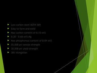
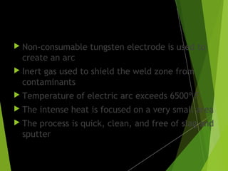
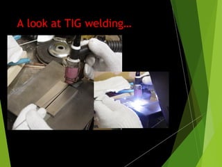
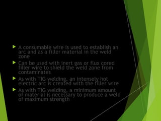
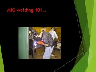
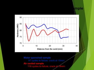
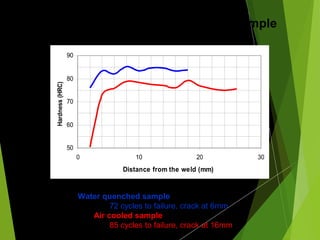
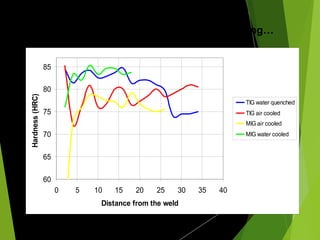
THE HEAT AFFECTED ZONE
Objectives:
 Analyze the heat affected zone (HAZ)
created by 3 types of welding and 2
different cooling rates
 Identify any changes in the properties of
the material characteristic of each type
of welding
 Identify any changes in the properties of
the material based on the method of
cooling used after welding
Parent metal:
 Low carbon steel ASTM 569
 Easy to form and weld
 Max carbon content of 0.15 wt%
 0.30 – 0.60 wt% Mg
 Max phosphorous content of 0.04 wt%
 55,000 psi tensile strength
 30,000 psi yield strength
 30% elongation
TIG welding:
 Non-consumable tungsten electrode is used to
create an arc
 Inert gas used to shield the weld zone from
contaminants
 Temperature of electric arc exceeds 6500º F
 The intense heat is focused on a very small area
 The process is quick, clean, and free of slag and
sputter
A look at TIG welding…
MIG welding:
 A consumable wire is used to establish an
arc and as a filler material in the weld
zone
 Can be used with inert gas or flux cored
filler wire to shield the weld zone from
contaminates
 As with TIG welding, an intensely hot
electric arc is created with the filler wire
 As with TIG welding, a minimum amount
of material is necessary to produce a weld
of maximum strength
MIG welding 101…
More MIG…
Gas welding:
 Brazing is a process of gas welding
 Oxygen and acetylene are burned at correct
proportions to create a flame ranging from 5800º
to 6300º F
 An alloy of a lower melting temperature is used to
join the parts of the base metal
 Brazing typically takes longer to weld than either
TIG or MIG
 The flame is not as intense or focused as an
electric arc
 Because of the inherently lower tensile strength of
brass, a proportionately larger amount of brass
must be used in the weld to provide sufficient
strength
Ancient and modern forms of gas welding…
…alternative forms of gas
welding
Getting the Right flame…
Procedure:
 Weld 2 sets of metal samples with TIG, MIG
and BRAZING
 One set is to be AIR COOLED at room
temperature
 The other set is to be WATER QUENCHED
 Conduct laboratory experimentation:
 Rockwell hardness measurements at 2mm
increments.
 Fatigue testing by bending the sample at
the joint 60º in both directions
 Collect and analyze data
 Discussion of results
Examples of some TIG welds…
Our TIG welded samples…
70
75
80
85
90
0 10 20 30 40
Distance from the weld (mm)
Hardness(HRC)
Hardness plot of the TIG welded sample
Water quenched sample
97 cycles to failure, crack at 10mm
Air cooled sample
116 cycles to failure, crack at 18mm
Our MIG welded samples…
50
60
70
80
90
0 10 20 30
Distance from the weld (mm)
Hardness(HRC)
Water quenched sample
72 cycles to failure, crack at 6mm
Air cooled sample
85 cycles to failure, crack at 16mm
Hardness plot of the MIG welded sample
Our Brazed welded sample…
Air cooled sample
6 cycles to failure, crack at welded joint
Water cooled sample
4 cycles to failure, crack at welded joint
Inconclusive Results !!
60
65
70
75
80
85
0 5 10 15 20 25 30 35 40
Distance from the weld
Hardness(HRC)
TIG water quenched
TIG air cooled
MIG air cooled
MIG water cooled
Hardness comparison of TIG and MIG welding…
Effects of different types of welding:
 TIG welding created a very strong weld with
good hardness and ductility
 MIG welding created a similarly strong weld
with slightly greater hardness values, less
ductility, and a smaller heat affected zone
than TIG
 Gas welding with brass created a weld of
insufficient strength hence its strength and
ductility could not be compared to the two
types of arc welding
Effects of different methods of
cooling:
 Typically the grain structure adjacent to the weld
has relatively lower hardness and greater ductility
associated with a coarse grain size. Water
quenching decreases the size of the grain
structure, thus raising the hardness.
 The next zone consists of a band of finer grains at
the critical temperature. This zone is relatively
harder and less ductile than the first zone and is
more prone to cracking. Water quenching tends
to harden this zone and causes cracks to occur
closer to the weld than air cooled samples.
 The third zone consists of a normal grain structure
resembling those of the parent metal and is
furthest from the weld.

The heat affected zone in welding

  • 1.
  • 2.
    Objectives:  Analyze theheat affected zone (HAZ) created by 3 types of welding and 2 different cooling rates  Identify any changes in the properties of the material characteristic of each type of welding  Identify any changes in the properties of the material based on the method of cooling used after welding
  • 3.
    Parent metal:  Lowcarbon steel ASTM 569  Easy to form and weld  Max carbon content of 0.15 wt%  0.30 – 0.60 wt% Mg  Max phosphorous content of 0.04 wt%  55,000 psi tensile strength  30,000 psi yield strength  30% elongation
  • 4.
    TIG welding:  Non-consumabletungsten electrode is used to create an arc  Inert gas used to shield the weld zone from contaminants  Temperature of electric arc exceeds 6500º F  The intense heat is focused on a very small area  The process is quick, clean, and free of slag and sputter
  • 5.
    A look atTIG welding…
  • 6.
    MIG welding:  Aconsumable wire is used to establish an arc and as a filler material in the weld zone  Can be used with inert gas or flux cored filler wire to shield the weld zone from contaminates  As with TIG welding, an intensely hot electric arc is created with the filler wire  As with TIG welding, a minimum amount of material is necessary to produce a weld of maximum strength
  • 7.
  • 8.
  • 9.
    Gas welding:  Brazingis a process of gas welding  Oxygen and acetylene are burned at correct proportions to create a flame ranging from 5800º to 6300º F  An alloy of a lower melting temperature is used to join the parts of the base metal  Brazing typically takes longer to weld than either TIG or MIG  The flame is not as intense or focused as an electric arc  Because of the inherently lower tensile strength of brass, a proportionately larger amount of brass must be used in the weld to provide sufficient strength
  • 10.
    Ancient and modernforms of gas welding…
  • 11.
  • 12.
  • 13.
    Procedure:  Weld 2sets of metal samples with TIG, MIG and BRAZING  One set is to be AIR COOLED at room temperature  The other set is to be WATER QUENCHED  Conduct laboratory experimentation:  Rockwell hardness measurements at 2mm increments.  Fatigue testing by bending the sample at the joint 60º in both directions  Collect and analyze data  Discussion of results
  • 14.
    Examples of someTIG welds…
  • 15.
    Our TIG weldedsamples…
  • 16.
    70 75 80 85 90 0 10 2030 40 Distance from the weld (mm) Hardness(HRC) Hardness plot of the TIG welded sample Water quenched sample 97 cycles to failure, crack at 10mm Air cooled sample 116 cycles to failure, crack at 18mm
  • 17.
    Our MIG weldedsamples…
  • 18.
    50 60 70 80 90 0 10 2030 Distance from the weld (mm) Hardness(HRC) Water quenched sample 72 cycles to failure, crack at 6mm Air cooled sample 85 cycles to failure, crack at 16mm Hardness plot of the MIG welded sample
  • 19.
  • 20.
    Air cooled sample 6cycles to failure, crack at welded joint Water cooled sample 4 cycles to failure, crack at welded joint Inconclusive Results !!
  • 21.
    60 65 70 75 80 85 0 5 1015 20 25 30 35 40 Distance from the weld Hardness(HRC) TIG water quenched TIG air cooled MIG air cooled MIG water cooled Hardness comparison of TIG and MIG welding…
  • 22.
    Effects of differenttypes of welding:  TIG welding created a very strong weld with good hardness and ductility  MIG welding created a similarly strong weld with slightly greater hardness values, less ductility, and a smaller heat affected zone than TIG  Gas welding with brass created a weld of insufficient strength hence its strength and ductility could not be compared to the two types of arc welding
  • 23.
    Effects of differentmethods of cooling:  Typically the grain structure adjacent to the weld has relatively lower hardness and greater ductility associated with a coarse grain size. Water quenching decreases the size of the grain structure, thus raising the hardness.  The next zone consists of a band of finer grains at the critical temperature. This zone is relatively harder and less ductile than the first zone and is more prone to cracking. Water quenching tends to harden this zone and causes cracks to occur closer to the weld than air cooled samples.  The third zone consists of a normal grain structure resembling those of the parent metal and is furthest from the weld.